EP0514944A2 - Véhicule avec au moins un essieu suspendu par coussin pneumatique - Google Patents
Véhicule avec au moins un essieu suspendu par coussin pneumatique Download PDFInfo
- Publication number
- EP0514944A2 EP0514944A2 EP92108713A EP92108713A EP0514944A2 EP 0514944 A2 EP0514944 A2 EP 0514944A2 EP 92108713 A EP92108713 A EP 92108713A EP 92108713 A EP92108713 A EP 92108713A EP 0514944 A2 EP0514944 A2 EP 0514944A2
- Authority
- EP
- European Patent Office
- Prior art keywords
- bellows
- vehicle
- vehicle according
- axle
- holding
- Prior art date
- Legal status (The legal status is an assumption and is not a legal conclusion. Google has not performed a legal analysis and makes no representation as to the accuracy of the status listed.)
- Withdrawn
Links
Images


Classifications
-
- B—PERFORMING OPERATIONS; TRANSPORTING
- B60—VEHICLES IN GENERAL
- B60G—VEHICLE SUSPENSION ARRANGEMENTS
- B60G17/00—Resilient suspensions having means for adjusting the spring or vibration-damper characteristics, for regulating the distance between a supporting surface and a sprung part of vehicle or for locking suspension during use to meet varying vehicular or surface conditions, e.g. due to speed or load
- B60G17/005—Suspension locking arrangements
-
- B—PERFORMING OPERATIONS; TRANSPORTING
- B60—VEHICLES IN GENERAL
- B60G—VEHICLE SUSPENSION ARRANGEMENTS
- B60G11/00—Resilient suspensions characterised by arrangement, location or kind of springs
- B60G11/32—Resilient suspensions characterised by arrangement, location or kind of springs having springs of different kinds
- B60G11/34—Resilient suspensions characterised by arrangement, location or kind of springs having springs of different kinds including leaf springs
- B60G11/46—Resilient suspensions characterised by arrangement, location or kind of springs having springs of different kinds including leaf springs and also fluid springs
- B60G11/465—Resilient suspensions characterised by arrangement, location or kind of springs having springs of different kinds including leaf springs and also fluid springs with a flexible wall
-
- B—PERFORMING OPERATIONS; TRANSPORTING
- B60—VEHICLES IN GENERAL
- B60G—VEHICLE SUSPENSION ARRANGEMENTS
- B60G7/00—Pivoted suspension arms; Accessories thereof
- B60G7/04—Buffer means for limiting movement of arms
-
- B—PERFORMING OPERATIONS; TRANSPORTING
- B60—VEHICLES IN GENERAL
- B60G—VEHICLE SUSPENSION ARRANGEMENTS
- B60G2202/00—Indexing codes relating to the type of spring, damper or actuator
- B60G2202/10—Type of spring
- B60G2202/11—Leaf spring
- B60G2202/112—Leaf spring longitudinally arranged
-
- B—PERFORMING OPERATIONS; TRANSPORTING
- B60—VEHICLES IN GENERAL
- B60G—VEHICLE SUSPENSION ARRANGEMENTS
- B60G2202/00—Indexing codes relating to the type of spring, damper or actuator
- B60G2202/10—Type of spring
- B60G2202/14—Plastic spring, e.g. rubber
- B60G2202/143—Plastic spring, e.g. rubber subjected to compression
-
- B—PERFORMING OPERATIONS; TRANSPORTING
- B60—VEHICLES IN GENERAL
- B60G—VEHICLE SUSPENSION ARRANGEMENTS
- B60G2202/00—Indexing codes relating to the type of spring, damper or actuator
- B60G2202/10—Type of spring
- B60G2202/15—Fluid spring
- B60G2202/152—Pneumatic spring
-
- B—PERFORMING OPERATIONS; TRANSPORTING
- B60—VEHICLES IN GENERAL
- B60G—VEHICLE SUSPENSION ARRANGEMENTS
- B60G2204/00—Indexing codes related to suspensions per se or to auxiliary parts
- B60G2204/40—Auxiliary suspension parts; Adjustment of suspensions
- B60G2204/45—Stops limiting travel
- B60G2204/4502—Stops limiting travel using resilient buffer
-
- B—PERFORMING OPERATIONS; TRANSPORTING
- B60—VEHICLES IN GENERAL
- B60G—VEHICLE SUSPENSION ARRANGEMENTS
- B60G2204/00—Indexing codes related to suspensions per se or to auxiliary parts
- B60G2204/40—Auxiliary suspension parts; Adjustment of suspensions
- B60G2204/46—Means for locking the suspension
- B60G2204/4604—Means for locking the suspension mechanically, e.g. using a hook as anticreep mechanism
-
- B—PERFORMING OPERATIONS; TRANSPORTING
- B60—VEHICLES IN GENERAL
- B60G—VEHICLE SUSPENSION ARRANGEMENTS
- B60G2204/00—Indexing codes related to suspensions per se or to auxiliary parts
- B60G2204/40—Auxiliary suspension parts; Adjustment of suspensions
- B60G2204/47—Means for retracting the suspension
- B60G2204/4702—Means for retracting the suspension pneumatically
Definitions
- the invention relates to a vehicle with at least one axle that is air-sprung via spring bellows.
- the bellows are held at one end on a bracket formed on the vehicle frame and at their other end on their rolling pot.
- the bellows usually have a bellows material consisting of rubber and a fabric insert.
- the bellows are kept under a certain air pressure.
- the bellows is partially compressed by the roll-off cup arranged on the vehicle frame or on the axle, thereby increasing the internal pressure in the bellows or lengthening the bellows and thus reducing the internal pressure.
- a force counteracting its deformation is generated in accordance with the excess pressure in the bellows.
- the bellows When the vehicle is at rest, the bellows is partially pre-compressed in order to be able to carry out a shortening stroke (compression) as well as an extension stroke (extension).
- the bellows can have a device for venting or venting, e.g. is used for level control. In both cases, it is obvious that the bellows must be airtight for safe use as a suspension element.
- the axles are relieved and hang due to their own weight from the underside of the vehicle.
- the disadvantage in this context is that the bellows are very stretched and due to the negative pressure in they are badly deformed.
- the outer walls drawn towards the inside of the bellows no longer roll properly on the roll-off pot. Instead, the outer walls between the roll-off pot and the vehicle frame or the bellows bracket are squeezed and damaged.
- a stop button arranged on the roll-off pot which is intended to prevent direct contact between the vehicle frame and the roll-off pot, can also crush and damage parts of the strongly deformed bellows.
- the object is achieved in that when the vehicle is lifted to limit an extension stroke of the bellows of the axle and / or the bellows a detachable stroke limiting device is associated.
- the stroke limiting device can directly to the axle and the bellows, for example if the bellows is motionally connected to the axle, or if the axle and bellows are separate, they can be assigned to one of the two.
- the stroke limiting device is designed to be detachable.
- the stroke limiting device can be manually operated using a device designed on the vehicle, e.g. Hydraulic or pneumatic device, but also mechanically solved.
- a safety rope can be arranged to hold the axle and to relieve the bellows, which hangs from the vehicle frame and surrounds the axle or is connected to the axle.
- the axle When the vehicle is lifted, the axle can be lowered to the lowest point of the rope length formed by the safety rope and is held by the safety rope at this point.
- the safety rope is used not to intercept the dead weight of the axle and the devices assigned to it via the bellows brackets and the bellows itself.
- the extension stroke of the bellows is not limited by the safety rope, but is fully utilized. An improvement in the rolling behavior of the bellows after lifting the vehicle cannot be achieved with the aid of the safety rope.
- the bellows is arranged above a roll-off pot which, with its roll-off body, is arranged on a longitudinal beam which is pivotably mounted on the vehicle frame and is motionally connected to the axle.
- the stroke limiting device can interact directly with the side member, the axis being along a due to the mounting of the side member Circular line is guided and can in principle be automatically brought closer to the stroke limiting device.
- the stroke limitation device is mounted on the vehicle frame.
- the stroke limiting device is pivotably mounted on the vehicle frame between a locking position and a release position. In this way, the stroke limiting device can be actuated in a simple manner both automatically and manually.
- the stroke limitation device Before lifting the vehicle, the stroke limitation device can be pivoted into the locking position and the axle can be locked directly or shortly after lifting has been initiated. After lowering the vehicle, the stroke limitation device will be pivoted into the release position. The vehicle and its suspension are ready for use again.
- the stroke limiting device for holding the axis in at least one position is designed as a holding hook with at least one holding lug, which is in engagement with a holding device arranged on the axis.
- the retaining hook it is also possible to design the retaining hook so that it grips around the axis directly at one point and thus fixes it.
- the retaining lug can be designed as a latching device which comes into contact with the latching device when the vehicle is lifted and latches with the latter.
- the holding device is designed with a holding bracket protruding in the direction of the holding hook. This comes into contact with the retaining lug of the stroke limiting device when it is pivoted into the locking position.
- the retaining hook has a plurality of retaining lugs, each with a receiving trough for the retaining bracket and a sliding bevel running between adjacent retaining lugs. The different positions of the axis are specified according to the distance between the retaining lugs.
- the holding bracket is securely received by the receiving trough. With the help of the sliding bevel, the axis is prevented from getting caught under the retaining lugs.
- the slide slope in the direction of the vehicle frame is inclined at an acute angle in the direction of the axis.
- the sliding bevel ensures that the holding bracket slides between successive receiving recesses and makes it easier to engage.
- the retaining bracket is subjected to force at least in the direction of its locking position.
- the holding hook is pressed in the direction of the holding bracket and when the vehicle is lifted, the holding hook slides into the next-lower receiving trough.
- This ensures that the bracket is snapped into the nearest receptacle, in particular when the vehicle is at different inclinations and there are different extension strokes for the bellows.
- the sliding path of the axis along the holding hook when lifting the vehicle is relatively long, since if the holding hook is formed with only one receiving trough, this is preferably formed at its end.
- the holding hook is designed as a two-armed lever, the holding lugs being formed on an axle lever arm assigned to the axis and a drive for pivoting the holding hook about a lever pivot bearing being arranged on the other pivoting lever arm .
- the drive can be operated manually with mechanical or with the help of the hydraulic or pneumatic system on the vehicle. In this way, the holding hook can be swiveled easily and quickly between the locking position and the release position.
- the drive is designed as a double-acting pneumatic cylinder. Due to the double action, i.e. of the pneumatic cylinder acting in two directions, the holding hook can easily be pivoted.
- At least one spring element is arranged between the vehicle frame and the holding hook for holding the holding hook in its locking and / or release position.
- the spring element is arranged at one end on the vehicle frame above the lever pivot bearing and the lever pivot bearing in the direction of the locking position of the holding hook and is arranged at the other end on the axle lever arm. This arrangement of the ends of the spring element relative to the lever pivot bearing is used to secure the hook Pressure loss over a dead center of the hooks held in the locked or unlocked position.
- the pneumatic cylinder can be controlled as a function of the lifting and lowering valves assigned to the bellows. Automatic control of the stroke limiting device is thus possible in a simple manner.
- the air bellows are connected to a pressure reservoir for ventilation.
- the bellows is ventilated when the vehicle is raised by the lifting valve and is vented by means of the lowering valve when the vehicle is lowered.
- a predetermined pressure can thus be applied to the bellows.
- At least one controllable two-way valve is arranged between the bellows and the pressure reservoir.
- the bellows can be aerated and vented using the two-way valve. It is possible to assign at least one vacuum valve to an axle or to assign a corresponding valve to each bellows on an axle.
- the two-way valve to maintain a given internal pressure in the bellows with measuring devices for determining the Underpressure and / or overpressure when lifting and / or lowering the vehicle is connected.
- the bellows can be aerated and vented automatically.
- the predetermined internal pressure in the bellows for example, the pressure when the vehicle is in the lowered state can be used. It is also possible to specify a lower internal pressure for the raised state of the vehicle, which is, however, large enough to prevent the side walls of the bellows from being sucked in.
- the pneumatic cylinder and / or the two-way valve for actuating the bellows can be controlled manually. Manual operation can be done from the driver's cab of the vehicle.
- each individual axle of the axle assembly can be equipped with the appropriate valves or a valve controls the ventilation of the entire axle assembly.
- the stroke limitation device fails, excessive vacuum or overpressure can be prevented when the vehicle is raised or lowered due to the ventilation of the bellows.
- the internal pressure in the bellows can be controlled, the bellows being ventilated to such an extent that the side walls are not or only very slightly sucked inwards when the vehicle is lifted, and the internal pressure is reduced so slowly and slowly when the vehicle is lowered that the bellows rolls correctly on the roll-off pot.
- Measuring devices on the bellows measure the corresponding deflection or rebound travel when raising or lowering the vehicle and can switch the two-way valve for ventilation in a known manner.
- the two-way valve can also be controlled indirectly via a control line by a check valve which switches over the two-way valve.
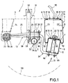
- FIG. 1 shows the vehicle 1 according to the invention in Detail of an axis 2 is shown with an associated suspension device.
- the electrical, pneumatic and hydraulic systems embodied in vehicle 1 are known in principle and are therefore not shown.
- a vehicle frame 4 is shown in a highly simplified manner, since its construction is also generally known to a person skilled in the art.
- One or more tires 59 rotatable about the axis of rotation 73 are arranged on the axis 2 on both sides.
- this is connected to the vehicle frame 4 via a trailing arm 13 and a bellows 3.
- a shock absorber 31 is also arranged between axle 2 and frame 4.
- the trailing link 13 comprises, for example, a bellows link 24 and a traction link 25. Both are pivotably mounted on a longitudinal beam bearing 26 with end sections 77 and 78 arranged concentrically to one another. This is arranged in a bearing frame 74 below the vehicle frame 4.
- the trailing arm 13 extends from the longitudinal beam bearing 26 in the direction of the vehicle axle 2 to the rolling pot 9.
- the vehicle axle 2 and trailing arm 13 are motionally connected by means of a holding frame 27.
- the holding frame 27 comprises an end plate 28, which rests on the pull link 25, and retaining screws 29 and 29 'which connect the holding frame and thus the pull link 25 and bellows link 24 with a fastening flange 30 arranged on the axle.
- the mounting flange 30 has an approximately flat surface, which is opposite the end plate 28 and between which the tension link 25 and bellows link 24 are enclosed.
- the lower bearing point 33 of the shock absorber 31 is arranged on the fastening flange 30 laterally to the vehicle axis. At the upper end, the shock absorber is mounted on a bearing point 32 on the frame 4 of the vehicle 1. To change the length of the shock absorber 31, the latter has a piston 38 which can be pushed out and is pivotably mounted at the lower bearing point 33.
- the trailing arm 13 extends from the longitudinal beam bearing 26 in the direction of the vehicle axis 2 to the rolling pot 9.
- a roll-off pot 9 is fastened by means of screws 66.
- This has essentially a cylindrical shape and carries at its upper end a holder 8 and a button-shaped buffer 22, which are fastened by means of a fastening bolt 20 to the upper end of the rolling pot 9.
- a bellows 3 is arranged between the rolling pot 9 and the vehicle frame 4. This is held at its upper end 6 on a bracket 5 on the frame 4 and at its lower end 7 on the bracket 8 of the rolling pot 9.
- the bellows 3 comprises a deformable bellows element 19 which is essentially cylindrical. Its upper edge 17 is fastened in a folded-over edge area 71 of the holder 5 which is to be turned towards one another.
- the lower edge of the bellows element 19 rests on the roll-off pot 9 and is fastened between an upwardly projecting, convexly curved edge 72 of the holder 8 and the roll-off pot 9.
- the side walls 23 and 23 'of the bellows element 19 extend essentially perpendicularly to the frame 4 and have pockets 70 and 70' lying laterally on a rolling body 12 of the rolling pot 9.
- the bracket 5 arranged on the vehicle frame 4 is designed with fastening screws 16 and 16 ′ connected to the interior of the bellows. Between the two valves, a compressed air line 60 is connected to a compressed air connection 35 for ventilating the bellows 3.
- the trailing arm 13 and the roll-off pot 9 move in directions 21. If the axis 2 is arranged with its axis of rotation in the position 73 ', the roll-off pot 9 is in its lowest position with an arrangement of the axis of rotation in the position 73 ′′, the rolling pot 9 is arranged in its highest position. These positions are described in more detail below.
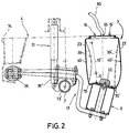
- the axis 2 is also arranged with its axis of rotation in the lowest position 73 'and the piston 38' 'of the shock absorber 31 is extended to the maximum.
- the bellows of Figure 2 is extended by the extension stroke 10 so that the pockets 70 and 70 'have almost completely disappeared.
- the side walls 23 and 23 ' By venting the bellows 3 by means of the compressed air line 60 and the compressed air connection 35 are the side walls 23 and 23 'arranged in a slightly outwardly curved ventilation position 40 and 40'.
- the side walls 23 and 23 ' are arranged in the inwardly curved vacuum position 39 and 39'.
- the extension stroke 10 ′ shown in FIG. 2 corresponds to the stroke of the bellows shown in FIG. 3 relative to the bellows shown in FIG. 1.
- the axis 2 is shown in its position closest to the frame.
- the axis of rotation is arranged in the position marked 73 '' in FIG.
- the trailing arm 13 is shown pivoted about the trailing arm axis of rotation 26 almost to the frame 4.
- the piston 38 'of the shock absorber 31 is maximally inserted into it.
- the side walls 23 and 23 'of the bellows 3 form the pockets 70 and 70' which almost completely cover the rolling body 12 of the rolling pot 9.
- the buffer 22 arranged at the upper end of the rolling pot 9 is in contact with the upper holder 5 of the bellows 3.
- the bellows 3 can be vented when the rolling pot approaches the holder 5.
- the side walls 23 and 23 'of the bellows 3 can be rolled along the rolling body 12 of the rolling pot 9, forming the pockets 70 and 70'. No sections of the side walls 23 or 23 'are clamped between the holder 5 and the buffer 22 or the rolling pot 9.
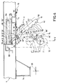
- a stroke limiting device 11 is shown in FIG.
- the same parts are again provided with the same reference numerals and are only mentioned in part.
- the stroke limiting device comprises a retaining hook 41 which is pivotably mounted in a pivot bearing 45.
- This is designed as a two-armed lever with a pivoting lever arm 47 and an axle lever arm 46.
- the axle lever arm 46 has a plurality of retaining lugs 42, receiving troughs 50 and sliding bevels 51 on its front side 43 facing the axle 2.
- the first holding lug 42 is arranged near the lower end 52 of the holding hook 41.
- the further retaining lugs 42 are arranged at regular intervals in the direction of the rotary bearing 45. Between each of the adjacent retaining lugs, the slide bevel 51 is arranged, which extends in the direction of the vehicle frame 4 by an acute angle ⁇ in the direction of the axis 2.
- the rear side 44 of the holding hook 41 runs essentially straight, with it curved at the lower end 52 in the direction of the first holding lug 42 of the front side 43.
- a bracket 48 is mounted on the axis 2 by means of a flange projecting in the direction of the retaining hook 41. When moving along the swivel circle 34, this can be arranged in a receiving recess 50 of the holding hook 41 in the locking position 14. If the axis 2 is pivoted about the longitudinal beam bearing 26 into the position 2 'by means of the longitudinal beam 13 (not shown in FIG. 4), the holding bracket 48' is in engagement with the receiving trough 50 '. In the highest Position is the axis 2 '' with its retaining bracket 48 '' above the receiving troughs of the retaining hook and with its front in contact.
- the lowest position 2 'of the axle is arranged closer to the vehicle frame 4 than the position shown in FIG.
- a pneumatic cylinder 54 with its movable piston 58 is mounted at its upper end 53.
- the bearing point 56 near the upper end 53 and at the opposite end a bearing point 55 fixed to the vehicle frame 4 is assigned to the pneumatic cylinder on the swivel lever arm 47 of the holding hook 41.
- the piston 58 can be moved along the actuation circle line 57.
- the pneumatic cylinder in the position 54 ' is arranged essentially parallel to the vehicle frame 4.
- the pneumatic cylinder 54 is arranged on the frame 4 pivoted downward at an acute angle in the direction of the axis 2.
- the pneumatic cylinder 54 is arranged in an essentially rectangular housing 68. This has a downward opening for the passage of the swivel lever arm 47, on which V-shaped bearing flanges 61 are arranged on both sides for mounting a swivel pin 62 of the holding hook 41.
- the bearing flange 61 has a pivot bearing bush 76 which is arranged concentrically with the axis of rotation 45.
- an essentially U-shaped frame 69 which is open at the bottom, is arranged for receiving the upper bearing point 32 of the shock absorber, not shown in FIG.
- a likewise U-shaped and downwardly open frame 67 is formed for mounting the housing on the holder 5 of the bellows element 19.
- the screws 16 and 16 ' can be arranged on both sides of the frame 67, the compressed air line and the associated compressed air connection according to FIGS. 1 to 3 not being shown in FIG. 4 for simplification.
- a connection of the bellows element 19 to a compressed air line or the arrangement of screws 16 and 16 ' is not necessary due to the stroke limiting device 11.
- FIG. 5 shows a section along the line V-V from FIG. 4.
- the holding hook 41 is arranged essentially vertically to the vehicle frame 4. Its upper end 53 is connected within the housing 68 to the piston 58 of the pneumatic cylinder 54.
- the pneumatic cylinder 54 is arranged in the housing 68 so as to be pivotable about the bearing axis 55.
- the housing 68 In the direction of the holding hook 41, the housing 68 is open and has bearing flanges 61 on both sides of the holding hook for mounting the pivot pin 62.
- the holding hook can be pivoted about the axis of rotation 45 by means of this pivot bolt.
- a pivot bearing bush 76 is arranged concentrically with the pivot pin 62 between the bearing flanges 61.
- a spring element 63 is arranged between the vehicle frame 4 and the axle lever arm 46.
- the spring element 63 is mounted on the frame 4 at its upper end 64 and 65 is at its lower end it is mounted on a holding arm 75 projecting perpendicularly from the axle lever arm 46.
- the spring element runs essentially parallel to the holding hook 41.
- the upper end 64 of the spring element 63 is arranged above and in the direction of the axis 2 upstream of the axis of rotation 45 of the holding hook 41.
- the lower end 65 is arranged below the axis of rotation and approximately in the center of the holding hook 41.
- the spring element 63 extends with respect to the axis of rotation 45 in the direction of the axis 2 in front of it and in the release position behind it.
- FIG. 4 it can be seen that when the vehicle is lifted, the holding bracket 48 slides into a receiving trough 50 of the holding hook 41 located in the locking position 14. Even when the vehicle is raised further, the axle 2 is fixed in this way and the extension stroke of the bellows 3 is limited. Depending on the condition of the vehicle, the axle can be in a 2 '' or 2 'position.
- the bellows 3 Simultaneously with the stroke limiting device 11, in the case of a bellows 3 that can be ventilated and vented, according to FIGS. 1 to 3, depending on the position of the axis 2, the bellows can be ventilated when the vehicle is raised according to FIG. 2 and vented when the vehicle is lowered according to FIG. 3.
- the effect of the stroke limiting device 11 is supported by controlled ventilation in the exemplary embodiment according to FIGS. 1 to 3.
- the bellows 3 rolls correctly on the rolling body 12 of the rolling pot 9 even when the vehicle is quickly lowered from the raised position.
Landscapes
- Engineering & Computer Science (AREA)
- Mechanical Engineering (AREA)
- Vehicle Body Suspensions (AREA)
Applications Claiming Priority (2)
| Application Number | Priority Date | Filing Date | Title |
|---|---|---|---|
| DE9106416U | 1991-05-24 | ||
| DE9106416U DE9106416U1 (de) | 1991-05-24 | 1991-05-24 | Fahrzeug mit mindestens einer über Federbälge luftgefederten Achse |
Publications (2)
| Publication Number | Publication Date |
|---|---|
| EP0514944A2 true EP0514944A2 (fr) | 1992-11-25 |
| EP0514944A3 EP0514944A3 (en) | 1993-01-27 |
Family
ID=6867637
Family Applications (1)
| Application Number | Title | Priority Date | Filing Date |
|---|---|---|---|
| EP19920108713 Withdrawn EP0514944A3 (en) | 1991-05-24 | 1992-05-22 | Vehicle with at least one axle, air-sprung by bellows |
Country Status (2)
| Country | Link |
|---|---|
| EP (1) | EP0514944A3 (fr) |
| DE (1) | DE9106416U1 (fr) |
Cited By (8)
| Publication number | Priority date | Publication date | Assignee | Title |
|---|---|---|---|---|
| US5197065A (en) * | 1989-09-26 | 1993-03-23 | International Business Machines Corporation | Distribution mechanism for establishing communications between user interfaces of a communication system |
| DE19539151A1 (de) * | 1995-10-20 | 1997-04-24 | Fichtel & Sachs Ag | Luftfeder |
| GB2345477A (en) * | 1999-01-11 | 2000-07-12 | Ashby Colin Hugh Pearson | Restraining device |
| WO2002047927A1 (fr) * | 2000-12-15 | 2002-06-20 | Meritor Heavy Vehicle Systems Limited | Suspension pneumatique pour vehicules |
| CN103707732A (zh) * | 2013-12-31 | 2014-04-09 | 重庆红岩方大汽车悬架有限公司 | 导向臂总成 |
| FR3004158A1 (fr) * | 2013-04-03 | 2014-10-10 | Renault Sa | Dispositif de maintien d'un train arriere de vehicule automobile lors de son montage |
| WO2015055268A1 (fr) * | 2013-10-16 | 2015-04-23 | Günter Michalke | Dispositif permettant de soulever des essieux |
| CN118876653A (zh) * | 2024-06-14 | 2024-11-01 | 东风商用车有限公司 | 一种复合空气悬架结构及车架 |
Families Citing this family (4)
| Publication number | Priority date | Publication date | Assignee | Title |
|---|---|---|---|---|
| DE9200350U1 (de) * | 1992-01-14 | 1992-02-27 | Karl Kässbohrer Fahrzeugwerke GmbH, 7900 Ulm | Fahrzeug mit wenigstens einer gegenüber am Fahrzeugrahmen mittels Luftbälgen gefederten Achse |
| EP0891264B1 (fr) | 1996-04-10 | 2002-07-10 | Holland USA, Inc. | Dispositif anti-glissement pour remorque a ressorts pneumatiques |
| EP0860306A1 (fr) * | 1997-02-20 | 1998-08-26 | BPW Bergische Achsen Kommanditgesellschaft | Ressort à air |
| WO2000041903A1 (fr) * | 1999-01-11 | 2000-07-20 | Ashby, Colin, Hugh, Pearson | Dispositif de retenue |
Family Cites Families (5)
| Publication number | Priority date | Publication date | Assignee | Title |
|---|---|---|---|---|
| FR848055A (fr) * | 1938-12-27 | 1939-10-23 | Perfectionnements apportés à la construction des véhicules pour faciliter le levage de ces véhicules | |
| US3719346A (en) * | 1968-10-17 | 1973-03-06 | J Bohannon | Automotive suspension ball joint checking mechanism and method |
| FR2594075B1 (fr) * | 1986-02-11 | 1988-05-20 | Trailor Sa | Dispositif de commande automatique de la suspension et des freins d'une semi-remorque du type rail-route et semi-remorque du type rail-route associee |
| BE1001918A3 (nl) * | 1988-12-02 | 1990-04-10 | Lag Mfg Cy N V | Inrichting voor het blokkeren van de as van een voertuig. |
| GB2244307B (en) * | 1990-04-05 | 1993-12-22 | Rubery Owen Rockwell Ltd | Method of releasably locking a movable component of a vehicle |
-
1991
- 1991-05-24 DE DE9106416U patent/DE9106416U1/de not_active Expired - Lifetime
-
1992
- 1992-05-22 EP EP19920108713 patent/EP0514944A3/de not_active Withdrawn
Cited By (10)
| Publication number | Priority date | Publication date | Assignee | Title |
|---|---|---|---|---|
| US5197065A (en) * | 1989-09-26 | 1993-03-23 | International Business Machines Corporation | Distribution mechanism for establishing communications between user interfaces of a communication system |
| DE19539151A1 (de) * | 1995-10-20 | 1997-04-24 | Fichtel & Sachs Ag | Luftfeder |
| GB2345477A (en) * | 1999-01-11 | 2000-07-12 | Ashby Colin Hugh Pearson | Restraining device |
| GB2345477B (en) * | 1999-01-11 | 2002-05-08 | Ashby Colin Hugh Pearson | Restraining device |
| WO2002047927A1 (fr) * | 2000-12-15 | 2002-06-20 | Meritor Heavy Vehicle Systems Limited | Suspension pneumatique pour vehicules |
| FR3004158A1 (fr) * | 2013-04-03 | 2014-10-10 | Renault Sa | Dispositif de maintien d'un train arriere de vehicule automobile lors de son montage |
| WO2015055268A1 (fr) * | 2013-10-16 | 2015-04-23 | Günter Michalke | Dispositif permettant de soulever des essieux |
| CN103707732A (zh) * | 2013-12-31 | 2014-04-09 | 重庆红岩方大汽车悬架有限公司 | 导向臂总成 |
| CN103707732B (zh) * | 2013-12-31 | 2017-01-11 | 重庆红岩方大汽车悬架有限公司 | 导向臂总成 |
| CN118876653A (zh) * | 2024-06-14 | 2024-11-01 | 东风商用车有限公司 | 一种复合空气悬架结构及车架 |
Also Published As
| Publication number | Publication date |
|---|---|
| DE9106416U1 (de) | 1991-07-04 |
| EP0514944A3 (en) | 1993-01-27 |
Similar Documents
| Publication | Publication Date | Title |
|---|---|---|
| DE69713877T2 (de) | Anti-kriech vorrichtung für anhänger mit luftfedern | |
| EP2539603B1 (fr) | Soufflet ventilé pour un ressort pneumatique, ressort pneumatique comprenant un soufflet ventilé et système de ressorts pneumatiques comprenant des soufflets ventilés | |
| EP0309760B1 (fr) | Tracteur de piste pour avion à force d'arrimage définie | |
| EP0514944A2 (fr) | Véhicule avec au moins un essieu suspendu par coussin pneumatique | |
| DE3934821C2 (fr) | ||
| DE8413300U1 (de) | Pneumatische Feder-Dämpfer-Einheit | |
| AT508096B1 (de) | Vorrichtung zum überführen einer seitenwand eines transportbehälters | |
| DE3309729A1 (de) | Achsanhebevorrichtung | |
| DE102006053523B3 (de) | Vorrichtung zum Überführen einer Wand eines Transportbehälters zwischen einer Schliessstellung und einer Offenstellung und Transportbehälter | |
| EP3546326A1 (fr) | Dispositif et procédé d'augmentation de la traction d'un tracteur | |
| DE102010040980B4 (de) | Luftfeder | |
| DE2508170A1 (de) | Lastfahrzeug | |
| DE2515679A1 (de) | Einrichtung zur verminderung der einwirkung von querkraeften bei kurvenfahrt und/oder einseitiger belastung auf in einem fahrzeug befindliche personen | |
| DE2318535C3 (de) | Nieveauregelventil für Luftfederungen von Fahrzeugen, insbesondere Container-Fahrzeugen | |
| DE765717C (de) | Steuerventil fuer Anhaenger-Druckmittelbremsen, insbesondere fuer Einkammer-Anhaengerbremsen | |
| DE9200350U1 (de) | Fahrzeug mit wenigstens einer gegenüber am Fahrzeugrahmen mittels Luftbälgen gefederten Achse | |
| DE8911010U1 (de) | Vorrichtung zur Einstellung der Höhe eines mit anhebbarer Achse versehenen Straßenfahrzeug-Rahmens im Verhältnis zum Boden | |
| CH675858A5 (fr) | ||
| DE2434265C2 (de) | Lastfahrzeug mit einer Wechselpritsche | |
| DE20101576U1 (de) | Luftfedervorrichtung für Radachsen von Nutzfahrzeugen | |
| EP0392380A1 (fr) | Dispositif de soulèvement d'un essieu suiveur d'un train de roulement à deux essieux d'un véhicule utilitaire | |
| DE102020109274B3 (de) | Zurröse mit Mittelstück zur Anordnung an einer Ladefläche eines Transportfahrzeuges | |
| EP0921970A1 (fr) | Procede pour assujettir un objet sur un vehicule | |
| AT394166B (de) | Vorrichtung zum trocknen einer seitenflaeche eines gewaschenen fahrzeuges in einer fahrzeugwaschanlage | |
| EP0481197B1 (fr) | Essieu à ressorts pneumatiques |
Legal Events
| Date | Code | Title | Description |
|---|---|---|---|
| PUAI | Public reference made under article 153(3) epc to a published international application that has entered the european phase |
Free format text: ORIGINAL CODE: 0009012 |
|
| AK | Designated contracting states |
Kind code of ref document: A2 Designated state(s): AT DE FR GB IT NL |
|
| PUAL | Search report despatched |
Free format text: ORIGINAL CODE: 0009013 |
|
| EL | Fr: translation of claims filed | ||
| AK | Designated contracting states |
Kind code of ref document: A3 Designated state(s): AT DE FR GB IT NL |
|
| STAA | Information on the status of an ep patent application or granted ep patent |
Free format text: STATUS: THE APPLICATION HAS BEEN WITHDRAWN |
|
| 18W | Application withdrawn |
Withdrawal date: 19930630 |
|
| R18W | Application withdrawn (corrected) |
Effective date: 19930630 |