EP0515077B1 - Assemblage d'ajutage et de valve - Google Patents
Assemblage d'ajutage et de valve Download PDFInfo
- Publication number
- EP0515077B1 EP0515077B1 EP92304284A EP92304284A EP0515077B1 EP 0515077 B1 EP0515077 B1 EP 0515077B1 EP 92304284 A EP92304284 A EP 92304284A EP 92304284 A EP92304284 A EP 92304284A EP 0515077 B1 EP0515077 B1 EP 0515077B1
- Authority
- EP
- European Patent Office
- Prior art keywords
- piston
- cylinder
- inlet
- liquid
- open end
- Prior art date
- Legal status (The legal status is an assumption and is not a legal conclusion. Google has not performed a legal analysis and makes no representation as to the accuracy of the status listed.)
- Expired - Lifetime
Links
- 239000007788 liquid Substances 0.000 claims abstract description 34
- 239000012530 fluid Substances 0.000 claims description 31
- 238000004891 communication Methods 0.000 claims description 10
- 238000000034 method Methods 0.000 claims description 6
- 235000013305 food Nutrition 0.000 claims description 5
- 238000004140 cleaning Methods 0.000 claims description 4
- 239000012265 solid product Substances 0.000 abstract description 15
- 239000007787 solid Substances 0.000 abstract description 7
- 239000000047 product Substances 0.000 description 24
- 239000012263 liquid product Substances 0.000 description 8
- IJGRMHOSHXDMSA-UHFFFAOYSA-N Atomic nitrogen Chemical compound N#N IJGRMHOSHXDMSA-UHFFFAOYSA-N 0.000 description 4
- 239000007789 gas Substances 0.000 description 4
- 230000001954 sterilising effect Effects 0.000 description 4
- 230000008878 coupling Effects 0.000 description 3
- 238000010168 coupling process Methods 0.000 description 3
- 238000005859 coupling reaction Methods 0.000 description 3
- 235000021055 solid food Nutrition 0.000 description 3
- 238000004659 sterilization and disinfection Methods 0.000 description 3
- 238000010586 diagram Methods 0.000 description 2
- 229910052757 nitrogen Inorganic materials 0.000 description 2
- 238000007599 discharging Methods 0.000 description 1
- 235000013399 edible fruits Nutrition 0.000 description 1
- 230000000694 effects Effects 0.000 description 1
- 239000011521 glass Substances 0.000 description 1
- 239000011261 inert gas Substances 0.000 description 1
- 235000013372 meat Nutrition 0.000 description 1
- 239000002184 metal Substances 0.000 description 1
- 239000000203 mixture Substances 0.000 description 1
- 238000004806 packaging method and process Methods 0.000 description 1
- 239000011087 paperboard Substances 0.000 description 1
- 239000002245 particle Substances 0.000 description 1
- 235000013547 stew Nutrition 0.000 description 1
- 239000000725 suspension Substances 0.000 description 1
- 235000015113 tomato pastes and purées Nutrition 0.000 description 1
- 235000013311 vegetables Nutrition 0.000 description 1
Images


Classifications
-
- B—PERFORMING OPERATIONS; TRANSPORTING
- B65—CONVEYING; PACKING; STORING; HANDLING THIN OR FILAMENTARY MATERIAL
- B65B—MACHINES, APPARATUS OR DEVICES FOR, OR METHODS OF, PACKAGING ARTICLES OR MATERIALS; UNPACKING
- B65B39/00—Nozzles, funnels or guides for introducing articles or materials into containers or wrappers
-
- B—PERFORMING OPERATIONS; TRANSPORTING
- B65—CONVEYING; PACKING; STORING; HANDLING THIN OR FILAMENTARY MATERIAL
- B65B—MACHINES, APPARATUS OR DEVICES FOR, OR METHODS OF, PACKAGING ARTICLES OR MATERIALS; UNPACKING
- B65B55/00—Preserving, protecting or purifying packages or package contents in association with packaging
- B65B55/02—Sterilising, e.g. of complete packages
Definitions
- This invention relates to a nozzle and valve assembly for supplying a product to each one of a series of containers.
- a device which is capable of supplying a predetermined amount of a product to each one of a series of containers.
- the product may be a mixture of a particulate solid product and a liquid.
- the device After a predetermined amount of product has been supplied to a container, there is the requirement for the device to provide a clean cut-off of the supply of the product without supplying any extra product until supply is recommenced for supplying the next container.
- GB-A-2089440 discloses a pump for metering two fluids, particularly a relatively thick fluid, such as a suspension of solid particles in a liquid, with an homogeneous liquid.
- the pump comprises a first cylinder containing a floating, solid, first piston and having an inlet conduit and an outlet conduit, a second piston in a second cylinder and for closing the communication between the first cylinder and its inlet conduit and between the first cylinder and its outlet conduit, alternately, the first piston drawing in the thick fluid from the inlet conduit and discharging it into the outlet conduit, and a third cylinder having a piston for drawing in the thin fluid from a second inlet conduit which piston has at least one port provided with one or more valves through which the thin fluid can flow to occupy the space between the first and third pistons where it can transmit the motion of the third piston to the first piston, and a by-pass for conveying thin fluid from the space between the pistons to the outlet conduit.
- the bypass serves to feed thin fluid to an inwardly directed nozzle in the lower end of the outlet conduit to inject thin fluid into the discharge section to wash away traces of the thick fluid from the lower end of the second piston and from the internal surface of the discharge section, which converges downwardly from just above the level of the nozzle.
- GB-A-1484763 discloses a filling head comprising a vertical, cylindrical casing having an axial outlet tube at its lower end for viscous product, such as tomato paste.
- An inlet for the product is spaced above the outlet at one side of the outlet tube and communicates with a product chamber between the inlet and the outlet.
- the outlet tube is adapted to fit into the neck of a container during filling.
- a rod is reciprocable co-axially of the casing and has a valve head adapted to move downwards into and seal the outlet tube.
- a short burst or premeasured quantity of atmosphere under pressure such as air, sterile inert gas, nitrogen or steam is fed through an axial conduit in the rod at the end of a filling cycle to cause residual product in the outlet tube to be pushed down into the neck of the container to prevent coning of the product.
- a nozzle and valve assembly comprising a cylinder having an open end, a first inlet leading into the interior of the cylinder, a second inlet, a piston having a free end and mounted for reciprocating movement in the cylinder at least between a first position and a second position, the piston permitting communication between the first inlet and the open end of the cylinder when the piston is in the first position, said free end of the piston moving past the first inlet as the piston moves from the first position to the second position so as to prevent communication between the first inlet and said open end of the cylinder, a fluid deflecting surface formed on said free end of the piston, means on the cylinder in the region of fluid deflecting surface when the piston is in the second position, and means for connecting the second inlet with the fluid directing means, characterised in that said fluid deflecting surface is conical and concave.
- a method of supplying a particulate product and a liquid to a container comprising the steps of:
- a nozzle and valve assembly 100 for supplying a predetermined amount of a particulate solid product followed by a predetermined amount of a liquid product to each one of a series of containers.
- the containers may be, for example, metal cans, plastic pots, paperboard cartons or glass jars.
- the particulate solid product may be, for example, a food product such as, suitably sized, whole sliced or diced vegetables and pieces of meat in the form of a stew, or various fruits in a compote.
- the liquid product will be a liquid which is suitable for combining with the solid food product.
- the particulate solid product may also be a non-food product.
- the nozzle and valve assembly 100 may also be used to supply a particulate solid product on its own.
- the food product may be supplied to the containers after sterilization.
- the product may be supplied before sterilization and, in this case, the product may then be sterilized in the containers after they have been sealed.
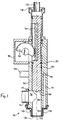
- the nozzle and valve assembly 100 includes a cylinder 102 and a piston 104 mounted for reciprocating movement in cylinder 102.
- the cylinder 102 has a cylindrical bore 106 and the lower end of cylinder 102 is open.
- An aperture 110 is formed in the wall of cylinder 102 towards its lower end.
- the opening 110 serves as a first inlet and this inlet receives, in use, a solid particulate product.
- a coupling member 112 for connecting the aperture 110 to a supply pipe 114.
- a second aperture 118 is formed in the wall of cylinder 102.
- This aperture 118 provides a second inlet which receives a fluid in the form of a liquid product or a gas.
- aperture 118 is connected with a supply pipe 120.
- the aperture 118 is also connected to an internal bore 119 which leads from aperture 118 towards the bottom of cylinder 102.
- the lower end of cylinder 102 terminates with a thin walled annular section 124.
- the annular section 124 is enclosed within an annular end member 126.
- the external surface of the annular section 124 and the internal surface of the annular end member 126 together define an axially extending annular passage 128 and an inwardly directed annular orifice 130.
- the annular passage 128 is in communication with the bore 119. As will be explained later, the orifice 130 directs fluid inwardly.
- the cylinder 102 is closed by a cover 130 which receives a supply pipe 132.
- a supply pipe 132 receives a supply pipe 132.
- the deflecting surface 140 is conical and concave and is symmetrical with respect to a central axis 142.
- the piston 104 is provided with a rack 146 which engages a semi-circular gear wheel 148 mounted on a housing 150.
- the gear wheel 148 is rotated by a motor or other actuator, not shown, thereby causing the piston 104 to reciprocate within cylinder 102.
- annular seal 152 is received in a groove formed in piston 104.
- the assembly 100 is shown in a state for supplying a predetermined amount of particulate solid product to a container.
- the piston 104 is raised into a first position so that its free end is level with the top of aperture 110.
- the solid food product passes the free end of piston 104, a portion of it may adhere to this free end.
- the deflecting surface 140 on the free end is conical and concave, it approximates to the form that sticky solids would naturally take up on the end of a piston. Consequently, the mass of solids which actually adhere to the free end of the piston will be minimal.
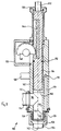
- the piston 104 descends, thereby closing off the inlet 110, until it reaches its second position as shown in Figure 2. In this second position, the free end of piston 104 is level with the bottom end of the annular section 124 of cylinder 102. When the piston 104 is in this second position, the assembly 100 is in a state for supplying liquid to the container.
- a predetermined amount of liquid may be supplied under pressure from a metering valve through supply pipe 120.
- the liquid passes through the aperture 118, bore 119, annular passage 128 and orifice 130.
- the orifice 130 directs the liquid inwardly and onto the fluid deflecting surface 140.
- the deflecting surface 140 progressively deflects the liquid downwardly so as to form it into a smooth slow flowing column of liquid. Because the liquid is formed into a column in this manner, air entrainment is avoided.
- liquid is prevented from flowing through the orifice 130 by surface tension. Thus, a clean cut-off is obtained and no drips of liquid fall from the assembly 100 between containers.
- the liquid passes over the fluid deflecting surface 140, it washes away any solid product which has adhered thereto.
- the assembly shown in Figures 1 to 3 is also suitable for supplying only a predetermined amount of a particulate solid product to each container and without the supply of any liquid product.
- the supply pipe 120 is connected through a valve to a source of a gas.
- the gas may be , for example, air, steam or nitrogen. Then, when the valve 104 is in the lower position shown in Figure 2, the valve is opened for a short period with the result that the gas is directed on to the fluid deflecting surface 140 and thereby blows any solids which have adhered thereto downwards into a container.
- the piston 104 When the assembly 100 is not supplying either a particulate solid product or a liquid product, the piston 104 may be retracted slightly upwardly from the position shown in Figure 2.
- FIG. 3 shows the position adopted by the piston 104 when it is desired to clean the assembly.
- a sterilizing fluid such as steam
- the supply pipes 114, 120 and 132 can pass through the upper part of cylinder 102 and into the interior of housing 150. It can also flow past the seal 152 and the outer surface of the lower part of piston 104 so that it is discharged through the open end of cylinder 102.
- a return pipe 154 for the cleaning fluids is connected to the lower end of the cylinder 102 by a coupling member 156.
- the coupling member 156 includes a valve for containing pressure.
- FIG 4 there is shown a block diagram of the assembly 100 together with a supply pipe 161 for a particulate solid product and a supply pipe 160 for a liquid product.
- the supply pipes 160,161 are connected through respective metering valves 162,163 to the supply pipes 120,114.
- the assembly 100 is shown supplying products to a container 164.
- the metering valves 162,163 of Figure 4 may take the form shown in published European patent application EP-A-0 280 537 or published European patent application EP-A-0 492 928 (prior art document according to Articles 54(3) and 54(4) EPC).
Landscapes
- Engineering & Computer Science (AREA)
- Mechanical Engineering (AREA)
- Basic Packing Technique (AREA)
- Nozzles (AREA)
- Containers And Packaging Bodies Having A Special Means To Remove Contents (AREA)
- Closures For Containers (AREA)
- Supply Of Fluid Materials To The Packaging Location (AREA)
- Feeding, Discharge, Calcimining, Fusing, And Gas-Generation Devices (AREA)
Claims (8)
- Un assemblage d'ajutage et de valve comprenant un cylindre (102) présentant une extrémité ouverte, une première entrée (110) menant à l'intérieur du cylindre (102), une seconde entrée (118), un piston (104) présentant une extrémité libre et montée pour se déplacer en va-et-vient dans le cylindre (102) au moins entre une première position (figure 1) et une seconde position (figure 2), le piston (104) permettant une communication entre la première entrée (110) et l'extrémité ouverte du cylindre (102) lorsque le piston (104) est dans la première position, ladite extrémité libre du piston (104) se déplaçant au-delà de la première entrée (110) lorsque le piston (104) se déplace depuis la première position jusqu'à la seconde position de manière à empêcher une communication entre la première entrée (110) et ladite extrémité ouverte du cylindre (102), d'une surface de déflection de fluide (140) formée sur ladite extrémité libre du piston, des moyens (130) sur le cylindre (102) dans la zone de ladite extrémité ouverte pour diriger du fluide vers l'intérieur et sur la surface de déflection de fluide (140) lorsque le piston (104) est dans la seconde position, et des moyens (119) pour relier la seconde entrée (118) aux moyens de direction de fluide (130), caractérisé en ce que ladite surface de déflection de fluide (140) est conique et concave.
- Un assemblage d'ajutage et de valve tel que revendiqué à la revendication 1, dans lequel les moyens de direction de fluide (130) comprennent un orifice annulaire dirigé vers l'intérieur (130) qui est disposé pour diriger du fluide sur la surface de déflection de fluide (140) lorsque le piston (104) est dans la seconde position (figure 2).
- Un assemblage d'ajutage et de valve tel que revendiqué à la revendication 1 ou 2, dans lequel ladite extrémité libre du piston (104) est adjacente à ladite extrémité ouverte du cylindre (102) lorsque le piston (104) est dans la seconde position (figure 2).
- Un assemblage d'ajutage et de valve tel que revendiqué dans une revendication précédente quelconque, et comprenant en outre une crémaillère (146) prévue sur ledit piston (104) et le long de celui-ci en étant espacée de ladite première entrée (110) dans une direction s'écartant de ladite extrémité ouverte dudit cylindre (102), et un pignon (148) en contact d'entraînement avec ladite crémaillère (146) et monté dans un boîtier (150) dont l'intérieur communique directement avec l'intérieur dudit cylindre (102).
- Un assemblage d'ajutage et de valve tel que revendiqué à la revendication 4 et comprenant en outre des moyens (132) pour introduire un fluide de nettoyage à l'intérieur dudit cylindre (102) et à l'intérieur dudit boîtier (150).
- Un procédé pour amener un produit particulaire et un liquide dans un récipient, ledit procédé comprenant les opérations consistant à :a) prévoir un assemblage d'ajutage et de valve (100) comprenant un cylindre (102) présentant une extrémité ouverte, une première entrée (110) menant à l'intérieur du cylindre (102), une seconde entrée (118), un piston (104) présentant une extrémité libre et monté pour se déplacer en va-et-vient dans le cylindre (102) au moins entre une première position (figure 1) et une seconde position (figure 2), le piston (104) permettant une communication entre la première entrée (110) et l'extrémité ouverte du cylindre (102) lorsque le piston (104) est dans la première position, ladite extrémité libre du piston (104) se déplacant au-delà de la première entrée (110) lorsque le piston (104) se déplace depuis la première position jusqu'à la seconde position de manière à empêcher une communication entre la première entrée (110) et ladite extrémité ouverte du cylindre (102), une surface de déflection de liquide (140) formée sur ladite extrémité libre du piston (104), des moyens (130) sur le cylindre (102) dans la zone de ladite extrémité ouverte pour diriger du liquide vers l'intérieur et sur la surface de déflection de liquide (140) lorsque le piston (104) est dans la seconde position, et des moyens (119) pour relier à la seconde entrée (118) avec les moyens de direction de fluide (130) ;b) mettre en place un récipient (164) en dessous de l'extrémité libre du cylindre (102) ;c) amener un produit particulaire à la premier entrée (110) lorsque le piston (104) est dans la première position (figure 1) ;d) déplacer le piston (104) depuis la première position (figure 1) jusqu'à la seconde position (figure 2) après qu'une quantité désirée du produit particulaire a été amenée au récipient (164) ; ete) amener le liquide à la seconde entrée (118) avec le piston (104) encore dans la seconde position (figure 2),caractérisé par l'opération consistant à amener un liquide à la seconde entrée (118) lorsque le piston (104) est dans la première position (figure 1).
- Un procédé comme revendiqué à la revendication 6, dans lequel le produit particulaire est un produit alimentaire.
- Un procédé comme revendiqué à la revendication 6 ou à la revendication 7, et comprenant en outre l'opération consistant à introduire un fluide de nettoyage à l'intérieur dudit cylindre (102) et à l'intérieur d'un boîtier (150) communiquant directement avec l'intérieur dudit cylindre (102) et à monter un pignon (148) en contact d'entraînement avec une crémaillère (146) prévue sur ledit piston (104) et le long de celui-ci.
Applications Claiming Priority (2)
| Application Number | Priority Date | Filing Date | Title |
|---|---|---|---|
| GB9111266 | 1991-05-24 | ||
| GB919111266A GB9111266D0 (en) | 1991-05-24 | 1991-05-24 | A nozzle |
Publications (2)
| Publication Number | Publication Date |
|---|---|
| EP0515077A1 EP0515077A1 (fr) | 1992-11-25 |
| EP0515077B1 true EP0515077B1 (fr) | 1997-10-22 |
Family
ID=10695561
Family Applications (1)
| Application Number | Title | Priority Date | Filing Date |
|---|---|---|---|
| EP92304284A Expired - Lifetime EP0515077B1 (fr) | 1991-05-24 | 1992-05-12 | Assemblage d'ajutage et de valve |
Country Status (7)
| Country | Link |
|---|---|
| US (1) | US5379921A (fr) |
| EP (1) | EP0515077B1 (fr) |
| JP (1) | JPH05193625A (fr) |
| AT (1) | ATE159479T1 (fr) |
| DE (1) | DE69222805T2 (fr) |
| GB (1) | GB9111266D0 (fr) |
| ZA (1) | ZA923605B (fr) |
Families Citing this family (3)
| Publication number | Priority date | Publication date | Assignee | Title |
|---|---|---|---|---|
| US5687779A (en) * | 1992-09-17 | 1997-11-18 | Tetra Laval Holdings & Finance S.A. | Packaging machine system for filling primary and secondary products into a container |
| NZ330709A (en) * | 1994-09-29 | 1999-01-28 | Tetra Laval Holdings & Finance | Fill system in a packaging machine includes user interface means and means to control pumps dispensing skim milk and cream into a container |
| JP6120027B2 (ja) * | 2015-10-01 | 2017-04-26 | 東洋製罐株式会社 | 充填装置 |
Citations (1)
| Publication number | Priority date | Publication date | Assignee | Title |
|---|---|---|---|---|
| GB2089440A (en) * | 1980-12-16 | 1982-06-23 | Nestle Sa | Pump |
Family Cites Families (7)
| Publication number | Priority date | Publication date | Assignee | Title |
|---|---|---|---|---|
| US3132808A (en) * | 1961-02-20 | 1964-05-12 | Spra Flo Equipment Co Inc | Mixing apparatus |
| SE306292B (fr) * | 1963-10-23 | 1968-11-25 | Kooperativa Foerbundet | |
| FR1482108A (fr) * | 1966-04-04 | 1967-05-26 | Rhone Poulenc Sa | Dispositif pour améliorer le conditionnement de produits filants et gluants |
| NL7004874A (fr) * | 1970-04-04 | 1971-10-06 | ||
| GB1484763A (en) * | 1975-10-10 | 1977-09-08 | Scholle Corp | Filling device |
| US4350187A (en) * | 1980-06-25 | 1982-09-21 | Pneumatic Scale Corporation | Filling machine |
| US4460025A (en) * | 1982-01-29 | 1984-07-17 | Scholle William J | Filling valve assembly with fiber shearing edge |
-
1991
- 1991-05-24 GB GB919111266A patent/GB9111266D0/en active Pending
-
1992
- 1992-05-12 DE DE69222805T patent/DE69222805T2/de not_active Expired - Fee Related
- 1992-05-12 AT AT92304284T patent/ATE159479T1/de active
- 1992-05-12 EP EP92304284A patent/EP0515077B1/fr not_active Expired - Lifetime
- 1992-05-18 ZA ZA923605A patent/ZA923605B/xx unknown
- 1992-05-19 US US07/977,513 patent/US5379921A/en not_active Expired - Fee Related
- 1992-05-22 JP JP4156115A patent/JPH05193625A/ja not_active Withdrawn
Patent Citations (1)
| Publication number | Priority date | Publication date | Assignee | Title |
|---|---|---|---|---|
| GB2089440A (en) * | 1980-12-16 | 1982-06-23 | Nestle Sa | Pump |
Also Published As
| Publication number | Publication date |
|---|---|
| DE69222805D1 (de) | 1997-11-27 |
| ATE159479T1 (de) | 1997-11-15 |
| US5379921A (en) | 1995-01-10 |
| EP0515077A1 (fr) | 1992-11-25 |
| JPH05193625A (ja) | 1993-08-03 |
| DE69222805T2 (de) | 1998-06-10 |
| GB9111266D0 (en) | 1991-07-17 |
| ZA923605B (en) | 1993-09-16 |
Similar Documents
| Publication | Publication Date | Title |
|---|---|---|
| EP0280537B1 (fr) | Système de dosage | |
| US3926229A (en) | Viscous material filling device | |
| US4375145A (en) | Packaging, particularly aseptic packaging of aseptic products in cartons | |
| JP2735329B2 (ja) | 包装機の洗浄清掃システム | |
| US5295523A (en) | Adjustable stroke multiple package filling apparatus | |
| US5038548A (en) | Defoaming method and apparatus | |
| US5865217A (en) | Fill system including a flexible nozzle for reducing the mixing of product and air during container filling | |
| EP0515077B1 (fr) | Assemblage d'ajutage et de valve | |
| US4402461A (en) | Fluid-handling apparatus | |
| EP0538956B1 (fr) | Dispositif de remplissage pour produits alimentaires visqueux | |
| US4317475A (en) | Liquid filling and level sensing apparatus | |
| KR20020092423A (ko) | 액체의 충전방법 | |
| US4838325A (en) | Method and an arrangement for a filling valve in a packing machine | |
| US5720326A (en) | Method and apparatus for filling a container with reduced mixing of product and air | |
| ES534287A0 (es) | Aparato para llenar envases con una cantidad dosificable de producto fluyente. | |
| US5775387A (en) | Container filling system having fill-pipe with an extended sealing member for reducing mixing of product and air during container filling | |
| EP0781226B1 (fr) | Machine de conditionnement | |
| EP0117329A2 (fr) | Ajutage de distribution d'un fluide et appareil d'alimentation, spécialement pour une machine d'emballage | |
| WO2025099692A1 (fr) | Système et procédé de remplissage de contenants avec des liquides | |
| EP1047599A1 (fr) | Systeme de remplissage pour produit liquide avec des particules | |
| JP4618979B2 (ja) | 容器充填用弁組立体 | |
| GB2246761A (en) | Liquid dispensing apparatus | |
| CN1007509B (zh) | 包装机的阀装置 | |
| WO1998005585A1 (fr) | Buse souple permettant de reduire le melange d'un produit a de l'air | |
| WO1985000575A1 (fr) | Procede et appareil pour debarrasser de la mousse un produit liquide pasteurise |
Legal Events
| Date | Code | Title | Description |
|---|---|---|---|
| PUAI | Public reference made under article 153(3) epc to a published international application that has entered the european phase |
Free format text: ORIGINAL CODE: 0009012 |
|
| 17P | Request for examination filed |
Effective date: 19920525 |
|
| AK | Designated contracting states |
Kind code of ref document: A1 Designated state(s): AT BE CH DE DK ES FR GB GR IT LI LU NL PT SE |
|
| RAP1 | Party data changed (applicant data changed or rights of an application transferred) |
Owner name: CARNAUDMETALBOX PLC |
|
| 17Q | First examination report despatched |
Effective date: 19940215 |
|
| RAP1 | Party data changed (applicant data changed or rights of an application transferred) |
Owner name: ODIN DEVELOPMENTS LIMITED |
|
| GRAG | Despatch of communication of intention to grant |
Free format text: ORIGINAL CODE: EPIDOS AGRA |
|
| GRAH | Despatch of communication of intention to grant a patent |
Free format text: ORIGINAL CODE: EPIDOS IGRA |
|
| GRAH | Despatch of communication of intention to grant a patent |
Free format text: ORIGINAL CODE: EPIDOS IGRA |
|
| GRAA | (expected) grant |
Free format text: ORIGINAL CODE: 0009210 |
|
| RAP1 | Party data changed (applicant data changed or rights of an application transferred) |
Owner name: ELOPAK A.S. |
|
| AK | Designated contracting states |
Kind code of ref document: B1 Designated state(s): AT BE CH DE DK ES FR GB GR IT LI LU NL PT SE |
|
| PG25 | Lapsed in a contracting state [announced via postgrant information from national office to epo] |
Ref country code: NL Free format text: LAPSE BECAUSE OF FAILURE TO SUBMIT A TRANSLATION OF THE DESCRIPTION OR TO PAY THE FEE WITHIN THE PRESCRIBED TIME-LIMIT Effective date: 19971022 Ref country code: LI Free format text: LAPSE BECAUSE OF FAILURE TO SUBMIT A TRANSLATION OF THE DESCRIPTION OR TO PAY THE FEE WITHIN THE PRESCRIBED TIME-LIMIT Effective date: 19971022 Ref country code: GR Free format text: LAPSE BECAUSE OF FAILURE TO SUBMIT A TRANSLATION OF THE DESCRIPTION OR TO PAY THE FEE WITHIN THE PRESCRIBED TIME-LIMIT Effective date: 19971022 Ref country code: ES Free format text: THE PATENT HAS BEEN ANNULLED BY A DECISION OF A NATIONAL AUTHORITY Effective date: 19971022 Ref country code: DK Free format text: LAPSE BECAUSE OF NON-PAYMENT OF DUE FEES Effective date: 19971022 Ref country code: CH Free format text: LAPSE BECAUSE OF FAILURE TO SUBMIT A TRANSLATION OF THE DESCRIPTION OR TO PAY THE FEE WITHIN THE PRESCRIBED TIME-LIMIT Effective date: 19971022 Ref country code: BE Free format text: LAPSE BECAUSE OF FAILURE TO SUBMIT A TRANSLATION OF THE DESCRIPTION OR TO PAY THE FEE WITHIN THE PRESCRIBED TIME-LIMIT Effective date: 19971022 Ref country code: AT Free format text: LAPSE BECAUSE OF FAILURE TO SUBMIT A TRANSLATION OF THE DESCRIPTION OR TO PAY THE FEE WITHIN THE PRESCRIBED TIME-LIMIT Effective date: 19971022 |
|
| REF | Corresponds to: |
Ref document number: 159479 Country of ref document: AT Date of ref document: 19971115 Kind code of ref document: T |
|
| REG | Reference to a national code |
Ref country code: CH Ref legal event code: EP |
|
| REF | Corresponds to: |
Ref document number: 69222805 Country of ref document: DE Date of ref document: 19971127 |
|
| ITF | It: translation for a ep patent filed | ||
| PG25 | Lapsed in a contracting state [announced via postgrant information from national office to epo] |
Ref country code: PT Free format text: LAPSE BECAUSE OF FAILURE TO SUBMIT A TRANSLATION OF THE DESCRIPTION OR TO PAY THE FEE WITHIN THE PRESCRIBED TIME-LIMIT Effective date: 19980122 |
|
| ET | Fr: translation filed | ||
| NLV1 | Nl: lapsed or annulled due to failure to fulfill the requirements of art. 29p and 29m of the patents act | ||
| REG | Reference to a national code |
Ref country code: CH Ref legal event code: PL |
|
| PG25 | Lapsed in a contracting state [announced via postgrant information from national office to epo] |
Ref country code: LU Free format text: LAPSE BECAUSE OF NON-PAYMENT OF DUE FEES Effective date: 19980512 |
|
| PLBE | No opposition filed within time limit |
Free format text: ORIGINAL CODE: 0009261 |
|
| STAA | Information on the status of an ep patent application or granted ep patent |
Free format text: STATUS: NO OPPOSITION FILED WITHIN TIME LIMIT |
|
| 26N | No opposition filed | ||
| REG | Reference to a national code |
Ref country code: GB Ref legal event code: IF02 |
|
| PGFP | Annual fee paid to national office [announced via postgrant information from national office to epo] |
Ref country code: FR Payment date: 20040408 Year of fee payment: 13 |
|
| PGFP | Annual fee paid to national office [announced via postgrant information from national office to epo] |
Ref country code: GB Payment date: 20040415 Year of fee payment: 13 |
|
| PGFP | Annual fee paid to national office [announced via postgrant information from national office to epo] |
Ref country code: SE Payment date: 20040421 Year of fee payment: 13 |
|
| PGFP | Annual fee paid to national office [announced via postgrant information from national office to epo] |
Ref country code: DE Payment date: 20040422 Year of fee payment: 13 |
|
| PG25 | Lapsed in a contracting state [announced via postgrant information from national office to epo] |
Ref country code: IT Free format text: LAPSE BECAUSE OF NON-PAYMENT OF DUE FEES;WARNING: LAPSES OF ITALIAN PATENTS WITH EFFECTIVE DATE BEFORE 2007 MAY HAVE OCCURRED AT ANY TIME BEFORE 2007. THE CORRECT EFFECTIVE DATE MAY BE DIFFERENT FROM THE ONE RECORDED. Effective date: 20050512 Ref country code: GB Free format text: LAPSE BECAUSE OF NON-PAYMENT OF DUE FEES Effective date: 20050512 |
|
| PG25 | Lapsed in a contracting state [announced via postgrant information from national office to epo] |
Ref country code: SE Free format text: LAPSE BECAUSE OF NON-PAYMENT OF DUE FEES Effective date: 20050513 |
|
| PG25 | Lapsed in a contracting state [announced via postgrant information from national office to epo] |
Ref country code: DE Free format text: LAPSE BECAUSE OF NON-PAYMENT OF DUE FEES Effective date: 20051201 |
|
| EUG | Se: european patent has lapsed | ||
| GBPC | Gb: european patent ceased through non-payment of renewal fee |
Effective date: 20050512 |
|
| PG25 | Lapsed in a contracting state [announced via postgrant information from national office to epo] |
Ref country code: FR Free format text: LAPSE BECAUSE OF NON-PAYMENT OF DUE FEES Effective date: 20060131 |
|
| REG | Reference to a national code |
Ref country code: FR Ref legal event code: ST Effective date: 20060131 |