EP0515085B1 - Kabel verbindende Struktur für einen Festkörper-Bildsensor - Google Patents
Kabel verbindende Struktur für einen Festkörper-Bildsensor Download PDFInfo
- Publication number
- EP0515085B1 EP0515085B1 EP92304317A EP92304317A EP0515085B1 EP 0515085 B1 EP0515085 B1 EP 0515085B1 EP 92304317 A EP92304317 A EP 92304317A EP 92304317 A EP92304317 A EP 92304317A EP 0515085 B1 EP0515085 B1 EP 0515085B1
- Authority
- EP
- European Patent Office
- Prior art keywords
- image sensing
- cable
- sensing device
- chassis
- female connector
- Prior art date
- Legal status (The legal status is an assumption and is not a legal conclusion. Google has not performed a legal analysis and makes no representation as to the accuracy of the status listed.)
- Expired - Lifetime
Links
Images


Classifications
-
- A—HUMAN NECESSITIES
- A61—MEDICAL OR VETERINARY SCIENCE; HYGIENE
- A61B—DIAGNOSIS; SURGERY; IDENTIFICATION
- A61B1/00—Instruments for performing medical examinations of the interior of cavities or tubes of the body by visual or photographical inspection, e.g. endoscopes; Illuminating arrangements therefor
- A61B1/04—Instruments for performing medical examinations of the interior of cavities or tubes of the body by visual or photographical inspection, e.g. endoscopes; Illuminating arrangements therefor combined with photographic or television appliances
- A61B1/05—Instruments for performing medical examinations of the interior of cavities or tubes of the body by visual or photographical inspection, e.g. endoscopes; Illuminating arrangements therefor combined with photographic or television appliances characterised by the image sensor, e.g. camera, being in the distal end portion
- A61B1/051—Details of CCD assembly
-
- H—ELECTRICITY
- H01—ELECTRIC ELEMENTS
- H01R—ELECTRICALLY-CONDUCTIVE CONNECTIONS; STRUCTURAL ASSOCIATIONS OF A PLURALITY OF MUTUALLY-INSULATED ELECTRICAL CONNECTING ELEMENTS; COUPLING DEVICES; CURRENT COLLECTORS
- H01R13/00—Details of coupling devices of the kinds covered by groups H01R12/70 or H01R24/00 - H01R33/00
- H01R13/62—Means for facilitating engagement or disengagement of coupling parts or for holding them in engagement
- H01R13/622—Screw-ring or screw-casing
-
- H—ELECTRICITY
- H01—ELECTRIC ELEMENTS
- H01R—ELECTRICALLY-CONDUCTIVE CONNECTIONS; STRUCTURAL ASSOCIATIONS OF A PLURALITY OF MUTUALLY-INSULATED ELECTRICAL CONNECTING ELEMENTS; COUPLING DEVICES; CURRENT COLLECTORS
- H01R13/00—Details of coupling devices of the kinds covered by groups H01R12/70 or H01R24/00 - H01R33/00
- H01R13/66—Structural association with built-in electrical component
- H01R13/665—Structural association with built-in electrical component with built-in electronic circuit
- H01R13/6683—Structural association with built-in electrical component with built-in electronic circuit with built-in sensor
-
- H—ELECTRICITY
- H04—ELECTRIC COMMUNICATION TECHNIQUE
- H04N—PICTORIAL COMMUNICATION, e.g. TELEVISION
- H04N23/00—Cameras or camera modules comprising electronic image sensors; Control thereof
- H04N23/50—Constructional details
- H04N23/54—Mounting of pick-up tubes, electronic image sensors, deviation or focusing coils
Definitions
- the present invention relates generally to a cable connecting structure of a solid state image sensing apparatus and, more particularly, to a camera cable connecting structure in a separate type camera consisting of a camera head and a camera control unit.
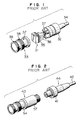
- Fig. 1 illustrates a conventional direct type cable fitting connecting method.
- Designated at 31 in Fig. 1 is an image sensing device module unit having its lead terminals 35 soldered to terminal members 36 of a camera cable 34. Thereafter, the image sensing device module unit is inserted into a body chassis 32 and a sheath chassis 33, and a connecting portion is fastened with a screw 37, whereby they are united.
- a direct type cable fitting camera head is thus completed.
- a thread 38 is formed on an outer periphery of the sheath chassis 33; and a lens (not illustrated) is thereby mountable thereto.
- Fig. 2 is another conventional example, showing a connector connecting method.
- Fig. 3 is a view fully illustrating this method of assembling a camera head.
- numeral 51 represents an image sensing device module unit to which a connecting plate 52 made of a flexible material is soldered to its lead terminals (not shown).
- Indicated at 53 is a connector constituting the other end (opposite to a lens mounting side) of the camera head and having at one end the lead terminals soldered to the connecting plate and at its other end a male connector connected to a female connector 41 integrally soldered to the camera cable 42.
- Numeral 54 denotes a sheath chassis into which a unit 55 consisting of the image sensing device, the connecting plate and the male connector is inserted.
- the external appearance of the camera based on the construction of Fig. 1 satisfies this demand of the customer because of the direct type cable fitting. Attaching and detaching the camera cable, however, involve demounting and mounting by hyperfine soldering. This presents a problem in that this operation is not easy, and the customer's demand can not then be satisfied. Further, in the construction of Fig. 2, the camera cable is attached and detached by the connector system, which facilitates the operation and meets this demand of the customer. In terms of the external appearance of the camera, however, a size of the female connector 41 is substantially equal to that of the camera head 43, which lacks smartness. Thus, a problem arises in that the wishes of the customer can not be satisfied.
- Applicant's copending European patent application No. 91121544.0 published as EP-A-0492349, discloses a compact camera head construction.
- the camera head comprises an image sensing module of identical construction to that of the present invention mounted within a chassis.
- the module has lead terminals which connect with a female connector located at an end of a cable for transmitting a signal received from an image sensing device chip of the module.
- EP-A-0492349 comprises a part of the state of the art according to Article 54(3) and (4) EPC since it has a priority date earlier than that of the present application but was published after the filing date of the present application.
- the present invention provides a solid state image sensing apparatus, comprising: a female connector fixed to a cable clamp; a cable connected to cable connecting terminals of said female connector, said cable passing through a through-hole of said cable clamp; an image sensing device module consisting of an image sensing device module unit in which an electrode of an image sensing device chip is connected through a metallic lead to electrodes disposed on side surfaces of device driving circuit boards and lead terminals are disposed on one of said boards, and a sheath chassis encasing said image sensing device module unit; said lead terminals of said image sensing device module transmit a signal from said image sensing device chip to the cable, characterised in that said lead terminals are joined to the female connector and said cable also passes through a through-hole in a body chassis and the body chassis is such that it covers the female connector joined to said lead terminals and the cable clamp.
- the camera head has a direct type cable fitting structure in terms of its external appearance.
- the cable can be demounted and mounted through the connector.
- Fig. 4 is a sketch drawing of a solid sate image sensing apparatus in accordance with the present invention.
- Fig. 5 illustrates a construction of the solid state image sensing apparatus of figure 4.
- Fig. 6 depicts a construction of an image sensing module unit in the embodiment.
- numeral 11 designates an image sensing device module; 12 a connector module; 13 a camera head; and 21 an image sensing device module unit consisting of lead terminals 22 comprising a pin function of a male connector, an image sensing device chip, a device driving circuit board and a spatial filter.
- the image sensing device module unit 21 is, as illustrated in Fig. 6, composed of an image sensing device chip 311, an optical glass 313, device driving circuit boards 314,315,316 each packed with a driving circuit for the image sensing device chip 311, and lead terminals 22.
- the optical glass 313 is fitted to a light receiving surface of the image sensing device chip 311.
- the device driving circuit boards 314,315,316 are held and fixed with connecting pins 317.
- Electrodes 314e, 315e,316e are formed on the side portions of the device driving circuit boards 314,315,316. These electrodes are connected to an outer lead 311m connected to a device electrode (unillustrated) of the image sensing device chip 311. Further, metallic lead terminals 22 are attached to the bottom of the device driving circuit board 316.
- numeral 23 represents a sheath chassis into which the image sensing device module unit 21 is fixedly inserted.
- An image sensing device module 11 is thus completed.
- Designated at 24 is a female connector fixed to a cable clamp 25 with a screw 26.
- a camera cable generally indicated at 27 passes through through-holes of the body chassis 28 and the cable clamp 25 and is thereafter fixed in a predetermined position in the cable clamp 25; and terminals thereof are soldered to cable connecting terminals 29 of the female connector 24.
- a connector unit 220 and a connector module 12 are thus completed.
- lead terminals pins 22 of the image sensing device module are connector-joined to the female connector 24 of the connector module.
- the body chassis and the cable clamp are screw-fastened and united by engaging a thread (unillustrated) formed inwardly of the body chassis 28 with a thread 213 formed on an outer periphery of the cable clamp, thus completing the camera head 13.
- a thread 214 is formed on an outer periphery of the sheath chassis 23, whereby a lens (not shown) is mountable thereto.
- the image sensing device module incorporates the image sensing device module unit in which the image sensing device chip is directly connected to the sheath chassis.
- the image sensing device module is connected to the connector module in which the body chassis incorporates the connector unit, thus completing the camera head.
- the camera head therefore has a direct type cable fitting structure in terms of its external appearance.
- the connector structure in which the cable is attachable and detachable simply by demounting the screw fastening portion of the connecting member.
Landscapes
- Health & Medical Sciences (AREA)
- Engineering & Computer Science (AREA)
- Life Sciences & Earth Sciences (AREA)
- Surgery (AREA)
- Heart & Thoracic Surgery (AREA)
- Microelectronics & Electronic Packaging (AREA)
- Signal Processing (AREA)
- Biophysics (AREA)
- Nuclear Medicine, Radiotherapy & Molecular Imaging (AREA)
- Optics & Photonics (AREA)
- Pathology (AREA)
- Radiology & Medical Imaging (AREA)
- Biomedical Technology (AREA)
- Multimedia (AREA)
- Molecular Biology (AREA)
- Medical Informatics (AREA)
- Physics & Mathematics (AREA)
- Animal Behavior & Ethology (AREA)
- General Health & Medical Sciences (AREA)
- Public Health (AREA)
- Veterinary Medicine (AREA)
- Studio Devices (AREA)
- Transforming Light Signals Into Electric Signals (AREA)
- Solid State Image Pick-Up Elements (AREA)
Claims (2)
- Festkörper-Bildabtastvorrichtung, aufweisend: eine Steckerbuchse (24), die mit einer Kabelklemme (25) verbunden ist; ein Kabel (27), das mit Kabelverbindungsanschlüssen (29) der Steckbuchse (24) verbunden ist, wobei das Kabel (27) durch ein Durchgangsloch der Kabelklemme (25) hindurchgeht; ein Bildabtastvorrichtungs-Modul (11), das aus einer Bildabtastvorrichtungs-Moduleinheit (21) besteht, in welcher eine Elektrode eines Bildabtastvorrichtungs-Chips (311) durch einen metallischen Leiter (311m) mit Elektroden (314e, 315e, 316e) verbunden ist, die an Seitenflächen von Vorrichtungstreiber-Schaltungskarten (314, 315, 316) angeordnet sind, wobei Leiteranschlüsse (22) auf einer (316) der Karten (314, 315, 316) angeordnet sind; und ein Mantelchassis (23), welches die Bildabtastvorrichtungs-Moduleinheit (21) umhüllt; wobei die Leiteranschlüsse (22) des Bildabtastvorrichtungs-Moduls (11) ein Signal von dem Bildabtastvorrichtungs-Chip (311) zum Kabel (27) übertragen, dadurch gekennzeichnet, daß die Leiteranschlüsse (22) mit der Steckbuchse (24) verbunden sind und das Kabel (27) auch durch ein Durchgangsloch in einem Körperchassis (28) hindurchgeht und das Körperchassis (28) derart beschaffen ist, daß es die mit den Leiteranschlüssen (22) und der Kabelklemme (25) verbundene Steckbuchse (24) verdeckt.
- Festkörper-Bildabtastvorrichtung nach Anspruch 1, dadurch gekennzeichnet, daß das Mantelchassis (23) und die Steckbuchse (24) miteinander durch eine Schraube (212) fest verbunden sind, das Körperchassis (28) und die Kabelklemme (25) miteinander verschraubt sind, und zwar durch in-Eingriff-Bringen eines im Inneren des Körperchassis ausgebildeten Gewindes mit einem am Außenumfang der Kabelklemme (25) ausgebildeten Gewinde (213), und auf diese Weise das Körperchassis (28) mit dem Mantelchassis (23) zusammengefügt ist.
Applications Claiming Priority (2)
| Application Number | Priority Date | Filing Date | Title |
|---|---|---|---|
| JP114767/91 | 1991-05-20 | ||
| JP3114767A JP2858173B2 (ja) | 1991-05-20 | 1991-05-20 | 固体撮像装置 |
Publications (3)
| Publication Number | Publication Date |
|---|---|
| EP0515085A2 EP0515085A2 (de) | 1992-11-25 |
| EP0515085A3 EP0515085A3 (en) | 1993-01-13 |
| EP0515085B1 true EP0515085B1 (de) | 1996-11-27 |
Family
ID=14646181
Family Applications (1)
| Application Number | Title | Priority Date | Filing Date |
|---|---|---|---|
| EP92304317A Expired - Lifetime EP0515085B1 (de) | 1991-05-20 | 1992-05-13 | Kabel verbindende Struktur für einen Festkörper-Bildsensor |
Country Status (4)
| Country | Link |
|---|---|
| US (1) | US5287191A (de) |
| EP (1) | EP0515085B1 (de) |
| JP (1) | JP2858173B2 (de) |
| DE (1) | DE69215433T2 (de) |
Families Citing this family (15)
| Publication number | Priority date | Publication date | Assignee | Title |
|---|---|---|---|---|
| GB2286501B (en) * | 1994-02-10 | 1998-04-15 | Robin Staniforth | Surveillance system and device |
| TW382180B (en) * | 1996-07-15 | 2000-02-11 | Sony Corp | Camera lens |
| JPH1032739A (ja) * | 1996-07-15 | 1998-02-03 | Sony Corp | 可撓性プリント配線基板装置 |
| FR2751197B1 (fr) * | 1996-07-18 | 1998-09-04 | Tokendo Sarl | Dispositif distal de sonde videoencoscopique, et sonde videoendoscopique munie de ce dispositif |
| US5946055A (en) * | 1996-08-16 | 1999-08-31 | Rosen Product Development, Inc. | Display unit |
| US6246449B1 (en) | 1996-08-16 | 2001-06-12 | Rosen Products Llc | Display unit |
| US6095970A (en) * | 1997-02-19 | 2000-08-01 | Asahi Kogaku Kogyo Kabushiki Kaisha | Endoscope |
| US6292236B1 (en) | 1999-03-26 | 2001-09-18 | Rosen Products Llc | Automotive-ceiling-mounted monitor |
| USD446507S1 (en) | 1999-06-18 | 2001-08-14 | Rosen Products Llc | Ceiling-mounted monitor |
| AUPQ641400A0 (en) * | 2000-03-23 | 2000-04-15 | Kleiner, Daniel E. | A device incorporating a hollow member for being positioned along a body cavity of a patient and method of positioning same |
| US20060217594A1 (en) * | 2005-03-24 | 2006-09-28 | Ferguson Gary W | Endoscopy device with removable tip |
| US8617059B2 (en) * | 2005-05-27 | 2013-12-31 | Olympus Corporation | Endoscopic apparatus and endoscope adapter |
| US20140188086A1 (en) * | 2012-12-31 | 2014-07-03 | Biosense Webster (Israel), Ltd. | Catheter connector |
| JP7372513B2 (ja) * | 2018-12-05 | 2023-11-01 | ミツミ電機株式会社 | 撮像デバイス、撮像システム、および産業用ロボット |
| KR102184079B1 (ko) * | 2019-02-01 | 2020-11-27 | 주식회사 지아이티 | 산업용 카메라 및 진단 시스템 |
Citations (1)
| Publication number | Priority date | Publication date | Assignee | Title |
|---|---|---|---|---|
| EP0492349A1 (de) * | 1990-12-28 | 1992-07-01 | Matsushita Electric Industrial Co., Ltd. | Kamerakopf für eine Festkörper-Bildaufnahme-Einrichtung und Verfahren zur Herstellung |
Family Cites Families (8)
| Publication number | Priority date | Publication date | Assignee | Title |
|---|---|---|---|---|
| US2890434A (en) * | 1955-10-21 | 1959-06-09 | Anatoly B Ray | Electrical disconnect safety lock |
| FR2274181A1 (fr) * | 1974-06-10 | 1976-01-02 | Inspectronic | Camera de television, cylindrique, compacte et dissociable |
| US4462653A (en) * | 1981-11-27 | 1984-07-31 | Bendix Corporation | Electrical connector assembly |
| US4838805A (en) * | 1984-01-05 | 1989-06-13 | Raytheon Company | Connector engaging nut locking mechanism |
| JPS6159974A (ja) * | 1984-08-31 | 1986-03-27 | Canon Inc | 電子カメラ及びレンズ鏡筒 |
| US4918521A (en) * | 1987-01-20 | 1990-04-17 | Olympus Optical Co., Ltd. | Solid state imaging apparatus |
| JPH0530307Y2 (de) * | 1987-02-12 | 1993-08-03 | ||
| US4974075A (en) * | 1987-08-11 | 1990-11-27 | Olympus Optical Co., Ltd. | Image pickup apparatus having connector capable of separately shielding grouped electrical connections |
-
1991
- 1991-05-20 JP JP3114767A patent/JP2858173B2/ja not_active Expired - Fee Related
-
1992
- 1992-05-08 US US07/879,903 patent/US5287191A/en not_active Expired - Fee Related
- 1992-05-13 EP EP92304317A patent/EP0515085B1/de not_active Expired - Lifetime
- 1992-05-13 DE DE69215433T patent/DE69215433T2/de not_active Expired - Fee Related
Patent Citations (1)
| Publication number | Priority date | Publication date | Assignee | Title |
|---|---|---|---|---|
| EP0492349A1 (de) * | 1990-12-28 | 1992-07-01 | Matsushita Electric Industrial Co., Ltd. | Kamerakopf für eine Festkörper-Bildaufnahme-Einrichtung und Verfahren zur Herstellung |
Also Published As
| Publication number | Publication date |
|---|---|
| EP0515085A2 (de) | 1992-11-25 |
| DE69215433D1 (de) | 1997-01-09 |
| EP0515085A3 (en) | 1993-01-13 |
| DE69215433T2 (de) | 1997-03-27 |
| JP2858173B2 (ja) | 1999-02-17 |
| JPH04342383A (ja) | 1992-11-27 |
| US5287191A (en) | 1994-02-15 |
Similar Documents
| Publication | Publication Date | Title |
|---|---|---|
| US5287191A (en) | Cable connector for separable type camera head | |
| US10518724B2 (en) | Method for assembling a vehicular camera | |
| US6654064B2 (en) | Image pickup device incorporating a position defining member | |
| US6977783B2 (en) | Lens module and assembling method thereof | |
| EP3430797B1 (de) | Kameraanordnung mit abgeschirmter bildgeberschaltung | |
| US4979787A (en) | Optical-electronic interface module | |
| US5667390A (en) | I/O card and its associated cable harness assembly | |
| JPH058405B2 (de) | ||
| JPH04303578A (ja) | プリント回路基板用のシールド付き電気コネクタ | |
| EP0886323A3 (de) | Substrat für ein Bildaufnahmevorrichtungsgehäuse | |
| US5875047A (en) | Optical transceiver unit | |
| US5190461A (en) | Connector assembly with both functions of coaxial connector and multiple contact connector | |
| US4699590A (en) | Modular connector assembly and filtered insert therefor | |
| EP1329754A2 (de) | Optisches Modul | |
| EP1248129A2 (de) | Optischer Stecker | |
| US5521670A (en) | Camera utilizing horizontal and vertical board connectors | |
| JP2001337249A (ja) | 光通信用レセプタクル | |
| EP3836529B1 (de) | Fahrzeugbildgebungsvorrichtung | |
| EP0921610A3 (de) | Elektrische Verbinderanordnung zur Montage auf einer Leiterplatte und Verfahren zur deren Montage | |
| CN219145476U (zh) | 镜头模组及车辆 | |
| JPH065765Y2 (ja) | 電子内視鏡 | |
| JP3092319B2 (ja) | 光送受信モジュールのパッケージ | |
| EP4387404A1 (de) | Elektronische vorrichtung | |
| JPS62163473A (ja) | 固体撮像素子取付構造 | |
| EP0368361B1 (de) | Elektronisches Gerät mit einem photoelektrischen Schalter |
Legal Events
| Date | Code | Title | Description |
|---|---|---|---|
| PUAI | Public reference made under article 153(3) epc to a published international application that has entered the european phase |
Free format text: ORIGINAL CODE: 0009012 |
|
| PUAL | Search report despatched |
Free format text: ORIGINAL CODE: 0009013 |
|
| AK | Designated contracting states |
Kind code of ref document: A2 Designated state(s): DE FR GB |
|
| AK | Designated contracting states |
Kind code of ref document: A3 Designated state(s): DE FR GB |
|
| 17P | Request for examination filed |
Effective date: 19930219 |
|
| 17Q | First examination report despatched |
Effective date: 19941011 |
|
| GRAG | Despatch of communication of intention to grant |
Free format text: ORIGINAL CODE: EPIDOS AGRA |
|
| GRAH | Despatch of communication of intention to grant a patent |
Free format text: ORIGINAL CODE: EPIDOS IGRA |
|
| GRAH | Despatch of communication of intention to grant a patent |
Free format text: ORIGINAL CODE: EPIDOS IGRA |
|
| GRAA | (expected) grant |
Free format text: ORIGINAL CODE: 0009210 |
|
| AK | Designated contracting states |
Kind code of ref document: B1 Designated state(s): DE FR GB |
|
| REF | Corresponds to: |
Ref document number: 69215433 Country of ref document: DE Date of ref document: 19970109 |
|
| ET | Fr: translation filed | ||
| PLBE | No opposition filed within time limit |
Free format text: ORIGINAL CODE: 0009261 |
|
| STAA | Information on the status of an ep patent application or granted ep patent |
Free format text: STATUS: NO OPPOSITION FILED WITHIN TIME LIMIT |
|
| 26N | No opposition filed | ||
| REG | Reference to a national code |
Ref country code: GB Ref legal event code: IF02 |
|
| PGFP | Annual fee paid to national office [announced via postgrant information from national office to epo] |
Ref country code: DE Payment date: 20050506 Year of fee payment: 14 |
|
| PGFP | Annual fee paid to national office [announced via postgrant information from national office to epo] |
Ref country code: GB Payment date: 20050511 Year of fee payment: 14 Ref country code: FR Payment date: 20050511 Year of fee payment: 14 |
|
| PG25 | Lapsed in a contracting state [announced via postgrant information from national office to epo] |
Ref country code: GB Free format text: LAPSE BECAUSE OF NON-PAYMENT OF DUE FEES Effective date: 20060513 |
|
| PG25 | Lapsed in a contracting state [announced via postgrant information from national office to epo] |
Ref country code: DE Free format text: LAPSE BECAUSE OF NON-PAYMENT OF DUE FEES Effective date: 20061201 |
|
| GBPC | Gb: european patent ceased through non-payment of renewal fee |
Effective date: 20060513 |
|
| REG | Reference to a national code |
Ref country code: FR Ref legal event code: ST Effective date: 20070131 |
|
| PG25 | Lapsed in a contracting state [announced via postgrant information from national office to epo] |
Ref country code: FR Free format text: LAPSE BECAUSE OF NON-PAYMENT OF DUE FEES Effective date: 20060531 |