EP0515210B1 - Entwicklungsgerät - Google Patents
Entwicklungsgerät Download PDFInfo
- Publication number
- EP0515210B1 EP0515210B1 EP92304667A EP92304667A EP0515210B1 EP 0515210 B1 EP0515210 B1 EP 0515210B1 EP 92304667 A EP92304667 A EP 92304667A EP 92304667 A EP92304667 A EP 92304667A EP 0515210 B1 EP0515210 B1 EP 0515210B1
- Authority
- EP
- European Patent Office
- Prior art keywords
- toner
- developing roller
- developing apparatus
- triboelectric charge
- developing
- Prior art date
- Legal status (The legal status is an assumption and is not a legal conclusion. Google has not performed a legal analysis and makes no representation as to the accuracy of the status listed.)
- Expired - Lifetime
Links
- 238000007600 charging Methods 0.000 claims description 65
- 239000000463 material Substances 0.000 claims description 51
- 238000009826 distribution Methods 0.000 claims description 45
- 238000011084 recovery Methods 0.000 claims description 37
- 230000002093 peripheral effect Effects 0.000 claims description 19
- 239000002245 particle Substances 0.000 claims description 18
- 238000011161 development Methods 0.000 claims description 16
- 238000000034 method Methods 0.000 claims description 15
- 238000003892 spreading Methods 0.000 claims description 6
- 230000007480 spreading Effects 0.000 claims description 6
- 230000008021 deposition Effects 0.000 claims description 3
- 239000011248 coating agent Substances 0.000 description 42
- 238000000576 coating method Methods 0.000 description 42
- 239000010410 layer Substances 0.000 description 27
- 229920005989 resin Polymers 0.000 description 18
- 239000011347 resin Substances 0.000 description 18
- VYPSYNLAJGMNEJ-UHFFFAOYSA-N Silicium dioxide Chemical compound O=[Si]=O VYPSYNLAJGMNEJ-UHFFFAOYSA-N 0.000 description 14
- -1 aliphatic amines Chemical class 0.000 description 14
- 229920001577 copolymer Polymers 0.000 description 14
- PPBRXRYQALVLMV-UHFFFAOYSA-N Styrene Chemical compound C=CC1=CC=CC=C1 PPBRXRYQALVLMV-UHFFFAOYSA-N 0.000 description 12
- 239000003795 chemical substances by application Substances 0.000 description 11
- 238000010276 construction Methods 0.000 description 11
- 239000000758 substrate Substances 0.000 description 10
- 230000001105 regulatory effect Effects 0.000 description 9
- 229910052751 metal Inorganic materials 0.000 description 8
- 239000002184 metal Substances 0.000 description 8
- 238000012546 transfer Methods 0.000 description 8
- 239000011247 coating layer Substances 0.000 description 7
- 239000004810 polytetrafluoroethylene Substances 0.000 description 7
- 229940058401 polytetrafluoroethylene Drugs 0.000 description 7
- 239000000377 silicon dioxide Substances 0.000 description 7
- OKTJSMMVPCPJKN-UHFFFAOYSA-N Carbon Chemical compound [C] OKTJSMMVPCPJKN-UHFFFAOYSA-N 0.000 description 6
- 238000001035 drying Methods 0.000 description 6
- 229920000728 polyester Polymers 0.000 description 6
- 229920000642 polymer Polymers 0.000 description 6
- 229920006311 Urethane elastomer Polymers 0.000 description 5
- 125000003277 amino group Chemical group 0.000 description 5
- 239000000975 dye Substances 0.000 description 5
- 229920001971 elastomer Polymers 0.000 description 5
- 239000000049 pigment Substances 0.000 description 5
- XEEYBQQBJWHFJM-UHFFFAOYSA-N Iron Chemical compound [Fe] XEEYBQQBJWHFJM-UHFFFAOYSA-N 0.000 description 4
- 239000011230 binding agent Substances 0.000 description 4
- 239000003086 colorant Substances 0.000 description 4
- 230000000052 comparative effect Effects 0.000 description 4
- 230000006866 deterioration Effects 0.000 description 4
- 238000007598 dipping method Methods 0.000 description 4
- 238000002474 experimental method Methods 0.000 description 4
- 238000005259 measurement Methods 0.000 description 4
- 150000003242 quaternary ammonium salts Chemical class 0.000 description 4
- 230000000717 retained effect Effects 0.000 description 4
- 229920001897 terpolymer Polymers 0.000 description 4
- 238000012360 testing method Methods 0.000 description 4
- 239000004952 Polyamide Substances 0.000 description 3
- 239000004743 Polypropylene Substances 0.000 description 3
- JUJWROOIHBZHMG-UHFFFAOYSA-N Pyridine Chemical compound C1=CC=NC=C1 JUJWROOIHBZHMG-UHFFFAOYSA-N 0.000 description 3
- YXFVVABEGXRONW-UHFFFAOYSA-N Toluene Chemical compound CC1=CC=CC=C1 YXFVVABEGXRONW-UHFFFAOYSA-N 0.000 description 3
- 239000002253 acid Substances 0.000 description 3
- 239000004489 contact powder Substances 0.000 description 3
- 238000010586 diagram Methods 0.000 description 3
- 230000000694 effects Effects 0.000 description 3
- 239000000806 elastomer Substances 0.000 description 3
- 230000002209 hydrophobic effect Effects 0.000 description 3
- 229920002647 polyamide Polymers 0.000 description 3
- 229920001225 polyester resin Polymers 0.000 description 3
- 239000004645 polyester resin Substances 0.000 description 3
- 229920001155 polypropylene Polymers 0.000 description 3
- 150000003440 styrenes Chemical class 0.000 description 3
- BFKJFAAPBSQJPD-UHFFFAOYSA-N tetrafluoroethene Chemical group FC(F)=C(F)F BFKJFAAPBSQJPD-UHFFFAOYSA-N 0.000 description 3
- RSWGJHLUYNHPMX-UHFFFAOYSA-N Abietic-Saeure Natural products C12CCC(C(C)C)=CC2=CCC2C1(C)CCCC2(C)C(O)=O RSWGJHLUYNHPMX-UHFFFAOYSA-N 0.000 description 2
- JOYRKODLDBILNP-UHFFFAOYSA-N Ethyl urethane Chemical compound CCOC(N)=O JOYRKODLDBILNP-UHFFFAOYSA-N 0.000 description 2
- YCKRFDGAMUMZLT-UHFFFAOYSA-N Fluorine atom Chemical compound [F] YCKRFDGAMUMZLT-UHFFFAOYSA-N 0.000 description 2
- KHPCPRHQVVSZAH-HUOMCSJISA-N Rosin Natural products O(C/C=C/c1ccccc1)[C@H]1[C@H](O)[C@@H](O)[C@@H](O)[C@@H](CO)O1 KHPCPRHQVVSZAH-HUOMCSJISA-N 0.000 description 2
- 239000004809 Teflon Substances 0.000 description 2
- 229920006362 Teflon® Polymers 0.000 description 2
- BZHJMEDXRYGGRV-UHFFFAOYSA-N Vinyl chloride Chemical compound ClC=C BZHJMEDXRYGGRV-UHFFFAOYSA-N 0.000 description 2
- NIXOWILDQLNWCW-UHFFFAOYSA-N acrylic acid group Chemical group C(C=C)(=O)O NIXOWILDQLNWCW-UHFFFAOYSA-N 0.000 description 2
- 239000000654 additive Substances 0.000 description 2
- 230000000996 additive effect Effects 0.000 description 2
- 230000008901 benefit Effects 0.000 description 2
- 230000015572 biosynthetic process Effects 0.000 description 2
- 229910052799 carbon Inorganic materials 0.000 description 2
- 239000006229 carbon black Substances 0.000 description 2
- 229920006026 co-polymeric resin Polymers 0.000 description 2
- 235000014113 dietary fatty acids Nutrition 0.000 description 2
- 239000000194 fatty acid Substances 0.000 description 2
- 229930195729 fatty acid Natural products 0.000 description 2
- 150000004665 fatty acids Chemical class 0.000 description 2
- 239000011737 fluorine Substances 0.000 description 2
- 229910052731 fluorine Inorganic materials 0.000 description 2
- 150000002222 fluorine compounds Chemical class 0.000 description 2
- 229910052742 iron Inorganic materials 0.000 description 2
- 239000012860 organic pigment Substances 0.000 description 2
- 239000005011 phenolic resin Substances 0.000 description 2
- 229920003229 poly(methyl methacrylate) Polymers 0.000 description 2
- 229920000098 polyolefin Polymers 0.000 description 2
- 230000002265 prevention Effects 0.000 description 2
- 239000005060 rubber Substances 0.000 description 2
- 229920002379 silicone rubber Polymers 0.000 description 2
- 239000004945 silicone rubber Substances 0.000 description 2
- 239000000344 soap Substances 0.000 description 2
- 239000007921 spray Substances 0.000 description 2
- 229910001220 stainless steel Inorganic materials 0.000 description 2
- 239000010935 stainless steel Substances 0.000 description 2
- 229920003048 styrene butadiene rubber Polymers 0.000 description 2
- 239000000126 substance Substances 0.000 description 2
- KHPCPRHQVVSZAH-UHFFFAOYSA-N trans-cinnamyl beta-D-glucopyranoside Natural products OC1C(O)C(O)C(CO)OC1OCC=CC1=CC=CC=C1 KHPCPRHQVVSZAH-UHFFFAOYSA-N 0.000 description 2
- JBHRGAHUHVVXQI-UHFFFAOYSA-N 1-triethoxysilylpropan-1-amine Chemical compound CCO[Si](OCC)(OCC)C(N)CC JBHRGAHUHVVXQI-UHFFFAOYSA-N 0.000 description 1
- VILCJCGEZXAXTO-UHFFFAOYSA-N 2,2,2-tetramine Chemical compound NCCNCCNCCN VILCJCGEZXAXTO-UHFFFAOYSA-N 0.000 description 1
- JZUHIOJYCPIVLQ-UHFFFAOYSA-N 2-methylpentane-1,5-diamine Chemical compound NCC(C)CCCN JZUHIOJYCPIVLQ-UHFFFAOYSA-N 0.000 description 1
- PYSRRFNXTXNWCD-UHFFFAOYSA-N 3-(2-phenylethenyl)furan-2,5-dione Chemical compound O=C1OC(=O)C(C=CC=2C=CC=CC=2)=C1 PYSRRFNXTXNWCD-UHFFFAOYSA-N 0.000 description 1
- QTBSBXVTEAMEQO-UHFFFAOYSA-M Acetate Chemical compound CC([O-])=O QTBSBXVTEAMEQO-UHFFFAOYSA-M 0.000 description 1
- QGZKDVFQNNGYKY-UHFFFAOYSA-O Ammonium Chemical compound [NH4+] QGZKDVFQNNGYKY-UHFFFAOYSA-O 0.000 description 1
- RYGMFSIKBFXOCR-UHFFFAOYSA-N Copper Chemical compound [Cu] RYGMFSIKBFXOCR-UHFFFAOYSA-N 0.000 description 1
- RPNUMPOLZDHAAY-UHFFFAOYSA-N Diethylenetriamine Chemical compound NCCNCCN RPNUMPOLZDHAAY-UHFFFAOYSA-N 0.000 description 1
- 239000001692 EU approved anti-caking agent Substances 0.000 description 1
- 229920000181 Ethylene propylene rubber Polymers 0.000 description 1
- 244000043261 Hevea brasiliensis Species 0.000 description 1
- 239000013032 Hydrocarbon resin Substances 0.000 description 1
- ZOKXTWBITQBERF-UHFFFAOYSA-N Molybdenum Chemical compound [Mo] ZOKXTWBITQBERF-UHFFFAOYSA-N 0.000 description 1
- 229920000459 Nitrile rubber Polymers 0.000 description 1
- 239000000020 Nitrocellulose Substances 0.000 description 1
- 229930182556 Polyacetal Natural products 0.000 description 1
- 239000005062 Polybutadiene Substances 0.000 description 1
- 239000004698 Polyethylene Substances 0.000 description 1
- NRCMAYZCPIVABH-UHFFFAOYSA-N Quinacridone Chemical compound N1C2=CC=CC=C2C(=O)C2=C1C=C1C(=O)C3=CC=CC=C3NC1=C2 NRCMAYZCPIVABH-UHFFFAOYSA-N 0.000 description 1
- 229920000147 Styrene maleic anhydride Polymers 0.000 description 1
- RTAQQCXQSZGOHL-UHFFFAOYSA-N Titanium Chemical compound [Ti] RTAQQCXQSZGOHL-UHFFFAOYSA-N 0.000 description 1
- 229920001807 Urea-formaldehyde Polymers 0.000 description 1
- FJWGYAHXMCUOOM-QHOUIDNNSA-N [(2s,3r,4s,5r,6r)-2-[(2r,3r,4s,5r,6s)-4,5-dinitrooxy-2-(nitrooxymethyl)-6-[(2r,3r,4s,5r,6s)-4,5,6-trinitrooxy-2-(nitrooxymethyl)oxan-3-yl]oxyoxan-3-yl]oxy-3,5-dinitrooxy-6-(nitrooxymethyl)oxan-4-yl] nitrate Chemical compound O([C@@H]1O[C@@H]([C@H]([C@H](O[N+]([O-])=O)[C@H]1O[N+]([O-])=O)O[C@H]1[C@@H]([C@@H](O[N+]([O-])=O)[C@H](O[N+]([O-])=O)[C@@H](CO[N+]([O-])=O)O1)O[N+]([O-])=O)CO[N+](=O)[O-])[C@@H]1[C@@H](CO[N+]([O-])=O)O[C@@H](O[N+]([O-])=O)[C@H](O[N+]([O-])=O)[C@H]1O[N+]([O-])=O FJWGYAHXMCUOOM-QHOUIDNNSA-N 0.000 description 1
- 239000006230 acetylene black Substances 0.000 description 1
- 150000007513 acids Chemical class 0.000 description 1
- 150000001252 acrylic acid derivatives Chemical class 0.000 description 1
- 229920000122 acrylonitrile butadiene styrene Polymers 0.000 description 1
- 230000009471 action Effects 0.000 description 1
- 239000002390 adhesive tape Substances 0.000 description 1
- 230000002411 adverse Effects 0.000 description 1
- 125000002723 alicyclic group Chemical group 0.000 description 1
- 125000001931 aliphatic group Chemical group 0.000 description 1
- 239000000956 alloy Substances 0.000 description 1
- 229910045601 alloy Inorganic materials 0.000 description 1
- 229910052782 aluminium Inorganic materials 0.000 description 1
- XAGFODPZIPBFFR-UHFFFAOYSA-N aluminium Chemical compound [Al] XAGFODPZIPBFFR-UHFFFAOYSA-N 0.000 description 1
- 150000003863 ammonium salts Chemical class 0.000 description 1
- PYKYMHQGRFAEBM-UHFFFAOYSA-N anthraquinone Natural products CCC(=O)c1c(O)c2C(=O)C3C(C=CC=C3O)C(=O)c2cc1CC(=O)OC PYKYMHQGRFAEBM-UHFFFAOYSA-N 0.000 description 1
- 150000004056 anthraquinones Chemical class 0.000 description 1
- 150000004982 aromatic amines Chemical class 0.000 description 1
- 125000003118 aryl group Chemical group 0.000 description 1
- 239000012298 atmosphere Substances 0.000 description 1
- UKXSKSHDVLQNKG-UHFFFAOYSA-N benzilic acid Chemical compound C=1C=CC=CC=1C(O)(C(=O)O)C1=CC=CC=C1 UKXSKSHDVLQNKG-UHFFFAOYSA-N 0.000 description 1
- 230000008859 change Effects 0.000 description 1
- 239000006231 channel black Substances 0.000 description 1
- 239000013522 chelant Substances 0.000 description 1
- 208000037516 chromosome inversion disease Diseases 0.000 description 1
- 238000004140 cleaning Methods 0.000 description 1
- 150000001875 compounds Chemical class 0.000 description 1
- 230000001276 controlling effect Effects 0.000 description 1
- 229910052802 copper Inorganic materials 0.000 description 1
- 239000010949 copper Substances 0.000 description 1
- 239000007822 coupling agent Substances 0.000 description 1
- 238000004132 cross linking Methods 0.000 description 1
- 230000003247 decreasing effect Effects 0.000 description 1
- 230000003467 diminishing effect Effects 0.000 description 1
- PPSZHCXTGRHULJ-UHFFFAOYSA-N dioxazine Chemical compound O1ON=CC=C1 PPSZHCXTGRHULJ-UHFFFAOYSA-N 0.000 description 1
- KPUWHANPEXNPJT-UHFFFAOYSA-N disiloxane Chemical class [SiH3]O[SiH3] KPUWHANPEXNPJT-UHFFFAOYSA-N 0.000 description 1
- QFTYSVGGYOXFRQ-UHFFFAOYSA-N dodecane-1,12-diamine Chemical compound NCCCCCCCCCCCCN QFTYSVGGYOXFRQ-UHFFFAOYSA-N 0.000 description 1
- 238000007786 electrostatic charging Methods 0.000 description 1
- 230000007613 environmental effect Effects 0.000 description 1
- 239000003822 epoxy resin Substances 0.000 description 1
- 150000002148 esters Chemical class 0.000 description 1
- 239000004744 fabric Substances 0.000 description 1
- 239000000945 filler Substances 0.000 description 1
- 239000006260 foam Substances 0.000 description 1
- 239000006232 furnace black Substances 0.000 description 1
- 239000011521 glass Substances 0.000 description 1
- LNEPOXFFQSENCJ-UHFFFAOYSA-N haloperidol Chemical compound C1CC(O)(C=2C=CC(Cl)=CC=2)CCN1CCCC(=O)C1=CC=C(F)C=C1 LNEPOXFFQSENCJ-UHFFFAOYSA-N 0.000 description 1
- 229920001519 homopolymer Polymers 0.000 description 1
- 229920006270 hydrocarbon resin Polymers 0.000 description 1
- PXZQEOJJUGGUIB-UHFFFAOYSA-N isoindolin-1-one Chemical compound C1=CC=C2C(=O)NCC2=C1 PXZQEOJJUGGUIB-UHFFFAOYSA-N 0.000 description 1
- 229920003049 isoprene rubber Polymers 0.000 description 1
- 125000001449 isopropyl group Chemical group [H]C([H])([H])C([H])(*)C([H])([H])[H] 0.000 description 1
- 239000007788 liquid Substances 0.000 description 1
- 229910044991 metal oxide Inorganic materials 0.000 description 1
- 150000004706 metal oxides Chemical class 0.000 description 1
- 239000000203 mixture Substances 0.000 description 1
- 230000004048 modification Effects 0.000 description 1
- 238000012986 modification Methods 0.000 description 1
- 229910052750 molybdenum Inorganic materials 0.000 description 1
- 239000011733 molybdenum Substances 0.000 description 1
- 238000000465 moulding Methods 0.000 description 1
- 229920003052 natural elastomer Polymers 0.000 description 1
- 229920001194 natural rubber Polymers 0.000 description 1
- 229920001220 nitrocellulos Polymers 0.000 description 1
- 229940079938 nitrocellulose Drugs 0.000 description 1
- 239000012188 paraffin wax Substances 0.000 description 1
- 235000019809 paraffin wax Nutrition 0.000 description 1
- 125000002080 perylenyl group Chemical group C1(=CC=C2C=CC=C3C4=CC=CC5=CC=CC(C1=C23)=C45)* 0.000 description 1
- CSHWQDPOILHKBI-UHFFFAOYSA-N peryrene Natural products C1=CC(C2=CC=CC=3C2=C2C=CC=3)=C3C2=CC=CC3=C1 CSHWQDPOILHKBI-UHFFFAOYSA-N 0.000 description 1
- 235000019271 petrolatum Nutrition 0.000 description 1
- 239000003208 petroleum Substances 0.000 description 1
- 150000004986 phenylenediamines Chemical class 0.000 description 1
- IEQIEDJGQAUEQZ-UHFFFAOYSA-N phthalocyanine Chemical compound N1C(N=C2C3=CC=CC=C3C(N=C3C4=CC=CC=C4C(=N4)N3)=N2)=C(C=CC=C2)C2=C1N=C1C2=CC=CC=C2C4=N1 IEQIEDJGQAUEQZ-UHFFFAOYSA-N 0.000 description 1
- 229920001084 poly(chloroprene) Polymers 0.000 description 1
- 229920001483 poly(ethyl methacrylate) polymer Polymers 0.000 description 1
- 229920002454 poly(glycidyl methacrylate) polymer Polymers 0.000 description 1
- 229920002285 poly(styrene-co-acrylonitrile) Polymers 0.000 description 1
- 229920002037 poly(vinyl butyral) polymer Polymers 0.000 description 1
- 229920000058 polyacrylate Polymers 0.000 description 1
- 239000004584 polyacrylic acid Substances 0.000 description 1
- 229920002857 polybutadiene Polymers 0.000 description 1
- 229920005668 polycarbonate resin Polymers 0.000 description 1
- 239000004431 polycarbonate resin Substances 0.000 description 1
- 229920000647 polyepoxide Polymers 0.000 description 1
- 229920000573 polyethylene Polymers 0.000 description 1
- 239000004926 polymethyl methacrylate Substances 0.000 description 1
- 229920006324 polyoxymethylene Polymers 0.000 description 1
- 229920002635 polyurethane Polymers 0.000 description 1
- 239000004814 polyurethane Substances 0.000 description 1
- 229920002689 polyvinyl acetate Polymers 0.000 description 1
- 239000011118 polyvinyl acetate Substances 0.000 description 1
- 229920000915 polyvinyl chloride Polymers 0.000 description 1
- 239000004800 polyvinyl chloride Substances 0.000 description 1
- 239000000843 powder Substances 0.000 description 1
- 238000003825 pressing Methods 0.000 description 1
- 150000003141 primary amines Chemical class 0.000 description 1
- UMJSCPRVCHMLSP-UHFFFAOYSA-N pyridine Natural products COC1=CC=CN=C1 UMJSCPRVCHMLSP-UHFFFAOYSA-N 0.000 description 1
- IZMJMCDDWKSTTK-UHFFFAOYSA-N quinoline yellow Chemical compound C1=CC=CC2=NC(C3C(C4=CC=CC=C4C3=O)=O)=CC=C21 IZMJMCDDWKSTTK-UHFFFAOYSA-N 0.000 description 1
- 239000002994 raw material Substances 0.000 description 1
- 238000005096 rolling process Methods 0.000 description 1
- 150000003839 salts Chemical class 0.000 description 1
- 150000003335 secondary amines Chemical class 0.000 description 1
- 229910000077 silane Inorganic materials 0.000 description 1
- 150000004756 silanes Chemical class 0.000 description 1
- 229920002545 silicone oil Polymers 0.000 description 1
- 239000007787 solid Substances 0.000 description 1
- 239000002904 solvent Substances 0.000 description 1
- 238000005507 spraying Methods 0.000 description 1
- 238000003756 stirring Methods 0.000 description 1
- 229920001909 styrene-acrylic polymer Polymers 0.000 description 1
- 125000000542 sulfonic acid group Chemical group 0.000 description 1
- 150000003505 terpenes Chemical class 0.000 description 1
- 235000007586 terpenes Nutrition 0.000 description 1
- 150000003512 tertiary amines Chemical class 0.000 description 1
- 239000006234 thermal black Substances 0.000 description 1
- JOUDBUYBGJYFFP-FOCLMDBBSA-N thioindigo Chemical compound S\1C2=CC=CC=C2C(=O)C/1=C1/C(=O)C2=CC=CC=C2S1 JOUDBUYBGJYFFP-FOCLMDBBSA-N 0.000 description 1
- 150000003609 titanium compounds Chemical class 0.000 description 1
- 229960001124 trientine Drugs 0.000 description 1
- WFKWXMTUELFFGS-UHFFFAOYSA-N tungsten Chemical compound [W] WFKWXMTUELFFGS-UHFFFAOYSA-N 0.000 description 1
- 229910052721 tungsten Inorganic materials 0.000 description 1
- 239000010937 tungsten Substances 0.000 description 1
- 239000001993 wax Substances 0.000 description 1
Images

Classifications
-
- G—PHYSICS
- G03—PHOTOGRAPHY; CINEMATOGRAPHY; ANALOGOUS TECHNIQUES USING WAVES OTHER THAN OPTICAL WAVES; ELECTROGRAPHY; HOLOGRAPHY
- G03G—ELECTROGRAPHY; ELECTROPHOTOGRAPHY; MAGNETOGRAPHY
- G03G15/00—Apparatus for electrographic processes using a charge pattern
- G03G15/02—Apparatus for electrographic processes using a charge pattern for laying down a uniform charge, e.g. for sensitising; Corona discharge devices
-
- G—PHYSICS
- G03—PHOTOGRAPHY; CINEMATOGRAPHY; ANALOGOUS TECHNIQUES USING WAVES OTHER THAN OPTICAL WAVES; ELECTROGRAPHY; HOLOGRAPHY
- G03G—ELECTROGRAPHY; ELECTROPHOTOGRAPHY; MAGNETOGRAPHY
- G03G15/00—Apparatus for electrographic processes using a charge pattern
- G03G15/06—Apparatus for electrographic processes using a charge pattern for developing
- G03G15/08—Apparatus for electrographic processes using a charge pattern for developing using a solid developer, e.g. powder developer
- G03G15/0806—Apparatus for electrographic processes using a charge pattern for developing using a solid developer, e.g. powder developer on a donor element, e.g. belt, roller
-
- G—PHYSICS
- G03—PHOTOGRAPHY; CINEMATOGRAPHY; ANALOGOUS TECHNIQUES USING WAVES OTHER THAN OPTICAL WAVES; ELECTROGRAPHY; HOLOGRAPHY
- G03G—ELECTROGRAPHY; ELECTROPHOTOGRAPHY; MAGNETOGRAPHY
- G03G13/00—Electrographic processes using a charge pattern
- G03G13/06—Developing
- G03G13/08—Developing using a solid developer, e.g. powder developer
Definitions
- This invention relates to a developing apparatus adapted for visualizing with a toner an electrostatic latent image formed on a sensitive drum by the electrophotographic method.
- a contact type developing apparatus having an essential construction as illustrated in Fig. 1, for example, has been known.
- the developing apparatus of this kind the development is accomplished by the following operation.
- a toner 2 placed in a toner container 1 is supplied onto a developing roller 5 by toner supplying means which comprises a stirrer 3, a toner supplying roller 4, etc.
- the toner 2 supplied to the developing roller 5 is retained in the form of a thin layer on the surface of the developing roller 5 and, at the same time, provided with electric charge of fixed magnitude by being passed through the area of a toner distribution and charging blade 6.
- the blade 6 has its end part disposed close to the peripheral surface of the developing roller 5 and its height is adjusted by a spring 6a.
- An electrostatic latent image formed on a sensitive drum 7 by an exposure device(omitted from illustration in the diagram) is developed by causing the toner deposited on the surface of the developing roller 5 to adhere to the sensitive drum 7 by means of development means.
- the electrostatic information recorded on the sensitive drum 7 is visualized.
- the visible image is recorded on a recording paper by a transfer device 8, for example.
- the residue of the toner remaining on the developing roller 5 is recovered into the toner container 1 by a recovery blade 9.
- 10 denotes a charging device and 11 a cleaning unit.
- the toner distribution and charging blade 6 mentioned above is generally formed of a rubber selected trom urethane rubber, silicone rubber, chloroprene rubber, butadiene rubber, isoprene rubber, acrylonitrile-butadiene rubber, ethylenepropylene rubber, and natural rubbers, a metal selected from iron, copper, aluminum, stainless steel, and alloys thereof, or a resin selected from phenol resin, hard vinyl chloride resin, polycarbonate resin, polyacetal resin, fluorine resin, and nitro-cellulose resin.
- the recovery blade 9 is produced by molding polyester, Teflon (tetrafluoroethylene resin), hard vinyl chloride, coated glass cloth, or acetate in the form of a tape or sheet and optionally coating the surface of the tape or sheet with a coating material.
- the developing roller 5 mentioned above is generally constructed, as illustrated in Fig. 2, by superposing on a metallic roller substrate 5a, an elastomer layer 5b of oilproof rubber and superposing on the elastomer layer 5b an electro-conductive layer 5c.
- This electroconductive layer 5c is generally formed by coating the elastomer layer 5b with an electroconductive coating material having an electroconductive filler dispersed in a commercially available solvent-soluble binder such as an electroconductive urethane type coating material or an electroconductive acrylic type coating material.
- the layer 5c possesses resistivity below approximately 10 10 ⁇ cm.
- the triboelectric charge imparting members such as, for example, the developing roller, the toner distribution and charging blade, the recovery blade, the toner supplying roller, and the toner container against which the toner particles produce friction desirably have opposite charging characteristics to the toner.
- the electrostatic charging property of the electroconductive layer (applied layer of an electroconductive coating material) of the developing roller is found by measurement in most cases to be equal in polarity to the toner polarity or, if opposite in polarity, to be substantially devoid of a charging ability.
- the electroconductive layer therefore, is incapable of conferring a proper triboelectric charge on the toner and is consequently liable to entail the disadvantage of inferior formation of the toner layer resulting in missing portions from a developed image or uneven thickness of the toner layer or inferior conveyance of the toner. Thus, the failure of the electroconductive layer to form a practically satisfactory image has been frequently encountered.
- the application to the toner distribution and charging blade 6 or the recovery blade 9 of triboelectric charge of the same magnitude as that applied to the developing roller 5 results in the following disadvantage.
- the toner tends to adhere to the toner distribution and charging blade 6 or the recovery blade 9 and the amount of the toner carried or transported by the developing roller 5 is decreased.
- the portion of the toner which escapes being transferred to the sensitive drum and survives consumption in image development is difficult to recover from the developing roller and the recovery blade to the toner container, with the result that a surplus of the toner spills down the toner container.
- U.S. Pat. No. 3,731,146 issued May 1, 1973 to A. C. Betting et al. discloses a doctor blade made of a material remote from the toner in the triboelectric series and close to the development roller surface material in the triboelectric series. This invention, however, discloses nothing about the fact that the triboelectric charge of the toner and the triboelectric charge of the developing roller surface are opposite in characteristics.
- U.S. Pat. No. 4,336,318 issued Jun. 22, 1982 to H. Fukumoto et al. discloses that the triboelectric charge of the toner q (c/g) and the thickness of the toner particle layer d (mm) are adjusted to satisfy the following formula in a method for developing electrostatic images: 3 x 10⁻⁸ ⁇
- This invention has no disclosure regarding the interrelation among the triboelectric charge of the toner, the triboelectric charge of the toner distribution and charging blade surface, the triboelectric charge of the developing roller surface, and the triboelectric charge of the recovery blade surface.
- U.S. Pat. No. 4,833,058 issued May 23, 1989 to Y. Hirano et al. discloses a blade composed of a silicone rubber comprising 100 parts by weight of a siloxane polymer having a cross linking density of 4 to 8 x 10 -4 mol/cc and 30 to 70 parts by weight of silica.
- This invention similarly to that of U.S. Pat. No. 4,336,318, fails to disclose anything about the interrelation among the triboelectric charge of the toner, the triboelectric charge of the toner distribution and charging blade surface, the triboelectric charge of the developing roller surface, and the triboelectric charge of the recovery blade surface.
- An object of this invention is to provide a developing apparatus which is capable of stably producing practically satisfactory images.
- Another object of this invention is to provide a developing apparatus which is enabled to impart appropriate triboelectric charge easily, constantly, and reliably to the toner particles being carried and transported on the developing roller by fully controlling the charging characteristics of the triboelectric charge imparting members such as, for example, the developing roller, the toner distribution and charging blade, and the recovery blade against which the toner particles generate friction.
- Still another object of this invention is to provide a developing apparatus which enables the toner to be thoroughly recovered without fail.
- a further object of this invention is to provide a developing apparatus of long service life.
- a developing apparatus comprising: a developing roller, toner supply means for supplying a toner to a peripheral surface of said developing roller, a toner distribution and charging blade for spreading said toner supplied to said peripheral surface of said developing roller into a thin layer, and development means for causing toner particles in said thin layer of toner formed on the peripheral surface of said developing roller to be electrostatically deposited on an electrostatic latent image carried on a sensitive drum and developed in a visible image thereon, characterized in that said toner is a one-component nonmagnetic toner, q 1 and q 2 are equal in polarity, and the relation,
- a developing apparatus comprising: a developing roller, toner supply means for supplying a toner to a peripheral surface of said developing roller, a toner distribution and charging blade for spreading said toner supplied to said peripheral surface of said developing roller into a thin layer, and development means for causing toner particles in said thin layer of toner formed on the peripheral surface of said developing roller to be electrostatically deposited on an electrostatic latent image carried on a sensitive drum and developed in a visible image thereon, characterized in that said toner is a one-component nonmagnetic toner and the relation, -4.
- q 1 stands for the specific triboelectric charge of said toner and q 3 for the specific triboelectric charge of the surface material of said developing roller, wherein q 1 and q 3 are determined by the method described.
- a developing apparatus comprising: a developing roller, toner supply means for supplying a toner to a peripheral surface of said developing roller, a toner distribution and charging blade for spreading said toner supplied to said peripheral surface of said developing roller into a thin layer, development means for causing toner particles in said thin layer of toner formed on the peripheral surface of said developing roller to be electrostatically deposited on an electrostatic latent image carried on a sensitive drum and developed in a visible image thereon, and a recovery blade for recovering the residue of the toner deposited on said developing roller after said deposition of said toner on said sensitive drum, characterized in that said toner is a one-component nonmagnetic toner, q 1 and q 4 are equal in polarity and the relation,
- the developing apparatus of this invention satisfies at least one of the following conditions.
- condition (1) mentioned above allows prevention of the adhesion of the toner particles to the toner distribution and charging blade and the shortage in triboelectric charging of the toner.
- condition of (1) is such that the difference between q 1 and q 2 is at least 250 nC.
- the developing roller is enabled to impart appropriate triboelectric charge to the toner.
- the electrostatic attraction between the toner and the developing roller surface is retained in an appropriate range, the efficiency of development is enhanced, and the amount of the toner deposited on the developing roller surface per unit area is retained in an appropriate range, and the problem of excess consumption of the toner and the problem of shortage of the toner in the development are overcome. Further, the problem of spill of the toner due to excessive deposition, the problem of insufficient recovery of the toner, and the problem of spill of the toner due to inferior triboelectric charging can be also eliminated.
- the relation of the quotient in the condition of (2) is desired to be -2.0 ⁇ q 1 /q 3 ⁇ -1.3, preferably -1.8 ⁇ q 1 /q 3 ⁇ -1.5.
- condition of (3) allows prevention of the adhesion of the toner particles to the recovery blade and the shortage of charging of the toner.
- the condition of (3) is desired to be such that the difference between q 1 and q 4 is at least 250 nC. In this case, the same effect as attained under the condition of (1) is accomplished by differentiating q 3 in polarity from q 1 and q 2 .
- the triboelectric charge, q, indicated herein with respect to a varying component member of the developing apparatus of this invention represents the magnitude determined by the use of an electrostatic coated surface analyzing device.
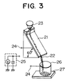
- Fig. 3 is a type illustration of the construction of one example of the electrostatic coated surface analyzing device (produced by Toshiba Chemical K.K.). The electrostatic coated surface analyzing device illustrated in Fig.
- triboelectric charge q is a procedure of fixing a metallic plate coated with a sample in place on a slanted plate 21, allowing a contact powder 22 to fall onto the metallic plate through a standard contact powder hopper 23, causing the triboelectric charge generated between the contact powder 22 rolling down the metallic plate and the metallic plate coated with the sample to be led by a meter connecting terminal 24 to an electro-meter 25 and subjected to measurement therein, and registering the outcome of the measurement as a "triboelectric charge q.”
- 26 is a receptacle and 27 is an insulating plate.
- the atmosphere of the site of determination is maintained at 25 °C and 55% RH, spherical iron particles 70 ⁇ m to 150 ⁇ m in diameter (a product of Powder Tech K.K. marketed under product code of "FL2030") are poured onto the metallic plate in a fixed amount of 1.3 g per round over a period of five seconds and allowed to roll down a distance of 90 mm on the metallic plate, the slanted plate 21 is fixed at an angle of 60 degrees, and the measurement is made at five points per sample.
- the metallic plate coated with a sample is a stainless steel plate measuring 75 mm x 100 mm in area. The coating is effected by the dipping method when the sample is in a liquid state. When the sample is in a solid state (in the form of sheet), it is cut into pieces of suitable size and applied to the metallic plate through the medium of an electroconductive double-face adhesive tape.
- the use of the electrostatic coated surface analyzing device constructed as described above enables the charging characteristics of a given surface with respect to the toner to be found practically.
- raw materials or coating materials for the relevant component members of the developing apparatus can be selected to satisfy the conditions of (1) to (3) mentioned above in accordance with the charging polarity and the triboelectric charge of the toner.
- the developing apparatus contemplated by this invention is constructed of these component members.
- the satisfaction of the conditions (1) to (3) mentioned above in the electroconductive layer of the developing roller is accomplished by incorporating in the electroconductive coating material or in the toner distribution and charging blade or the recovery blade by incorporating in the coating material applied to the surface of the substrate thereof a pertinent material indicated below in a proportion selected in the range of from 0.1% by weight to 100% by weight in accordance with the triboelectric charge aimed at.
- a coating material containing a charge regulating agent capable of improving the charging property in the positive direction is used.
- the charge regulating agents which improve the charging property in the positive direction include azine type nigrosine bases, electron donating dyes such as nigrosine derivatives, polymers such as styrene-acryl-quaternary ammonium salt copolymers, styrene-quaternary ammonium salt copolymers, acryl-quaternary ammonium salt copolymers, butadiene-acryl-quaternary ammonium salt copolymers, and butadiene-acryl-styrene-quaternary ammonium salt copolymers which contain a quaternary ammonium salt as a component unit, organic quaternary ammonium salts such as benzomethyl-hexyldecyl ammonium, silane compounds containing an amino group such as ⁇ -amino
- a coating layer containing a charge regulating agent capable of improving the charging property in the negative direction is formed on the surfaces of the developing roller, the toner distribution and charging blade, and the recovery blade.
- the charge regulating agents which improve the charging property in the negative direction include metal complexes of azo type dyes, electron accepting dyes such as metal complexes of alkylsalicylic acids and alkyl-naphthoic acids, fluorine compounds such as tetrafluoroethylene, chlorinated polyolefin, polyester resins of high acid values, hydro-phobic silica, and organic pigments containing a sulfonic acid group, for example.
- any of the materials heretofore used as for the toner distribution and charging blade and the recovery blade can be used.
- PTFE polytetra-fluoroethylene
- the PTFE which has a fibrous internal texture can be used directly as the recovery blade and the toner distribution and charging blade in this invention because it is soft, because it is readily formable especially for the recovery blade, and because the charging characteristics of the surface thereof fall in a range suitable for the impartation of a negative charging property.
- the adoption of the PTFE possessing this fibrous texture for the recovery blade and the toner distribution and charging blade brings about the advantage of diminishing the deformation and the change of pressing force due to the wear during a protracted service.
- the known one-component nonmagnetic toner which is composed of a resin binder, a coloring agent, a charge regulating agent, wax, and an anticaking agent is used.
- the resin binder various resin binders such as styrene polymers and substituted styrene polymers and acryl type resins which have been heretofore used for the toners of interest are available.
- the styrene polymers and substituted styrene polymers mentioned above include styrene homopolymers, hydrogenated styrene resins, styrene-isobutylene copolymer, styrene-butadiene copolymer, acrylonitrile-butadiene-styrene terpolymer, acrylonitrile-styrene-acrylic ester terpolymer, styrene-acrylonitrile copolymer, acrylonitrile-acryl rubber-styrene terpolymer, acrylonitrile-chlorinatedpolystyrene styrene terpolymer, acrylonitrile-EVA-styrene terpolymer, styrene-p-chlorostyrene copolymer, styrene-propylene copolymer, styrene-butadiene rubber
- the acrylic type resins mentioned above include polyacrylates, polymethyl methacrylates, polyethyl methacrylates, poly-n-butyl methacrylates, polyglycidyl methacrylates, fluorine-containing poly-acrylates, styrene-methacrylate copolymers, styrene-butyl meth-acrylate copolymers, and styrene-ethyl acrylate copolymer, for example.
- polyvinyl chloride polyvinyl acetate, polyethylene, polypropylene, polyesters, polyurethane, polyamides, epoxy resins, phenol resins, urea resins, polyvinyl butyral, poly-acrylic acid resin, rosin, modified rosin, terpene resins, aliphatic or alicyclic hydrocarbon resins, aromatic petroleum resins, chlorinated paraffins, and paraffin waxes can be used either independently or in a suitably combined form.
- the coloring agents which are usable for a colored toner include such known pigments and dyes as insoluble azo pigments, azo lakes, condensed azo pigments, chelate azo pigments, phthalocyanin pigments, anthraquinone, perylene, thioindigo, quinacridone, dioxazine, iso indolinone, and quinophthalone, for example.
- These color toner grade coloring agents can be used in the form a combination of two or more members.
- carbon black is mainly used. Carbon black is not specifically discriminated on account of its origin.
- Acetylene black, furnace black, thermal black, channel black, and ketzen black can be used also independently or in the form of a mixture of two or more members.
- two or more color toner grade coloring agents mentioned above may be used as suitably combined.
- the charge regulating agents which are effectively usable herein include metal chelates of alkyl salicylic acids, metal chelates of alkyl naphthoic acids, metal chelates of benzylic acid, quaternary ammonium salts, chlorinated polyesters, high acid valve polyesters, chlorinated polyolefins, metal salts of fatty acids, negative polarity regulating agents such as fatty acid soaps, dimethylaminoethyl methacrylate-styrene copolymer, fluorine-activating agents, and positive polarity regulating agents such as hydrophobic silica, for example.
- the anticaking agents which are effectively usable herein include hydrophobic silica, metallic soaps, fluorides, metal oxides, and minute spherical resin particles of PMMA, Teflon (tetrafluoroethylene resin), and styrene, for example.
- the developing apparatus of this invention which comprises the component elements described above is capable of imparting effective electric charge stably to the toner, the image characteristics can be enhanced and line images can be produced clearly and wholly black images uniformly easily at all times. The necessary functions can be retained for a long time without any sacrifice of the characteristics of the toner in spite of adverse environmental conditions.
- the developing apparatus of this invention promises many advantages in point of actual use. Moreover, the problem of spill of the toner from the developing apparatus can be prevented infallibly.
- Fig. 1 is a cross section illustrating the essential construction of a developing apparatus.
- Fig. 2 is a partially cutaway perspective view illustrating the construction of a developing roller.
- Fig. 3 is a diagram illustrating the operating principle of an electrostatic coated surface analyzing device for use in the determination of charging.
- a toner distribution and charging blade having a coating layer formed on the surface thereof with an electroconductive coating material possessed of a triboelectric charge of -70 nC as determined with the aforementioned coated surface analyzing device under the aforementioned conditions was prepared.
- this toner distribution and charging blade was produced by applying an electroconductive coating material (a product of Shinto Chemitron K.K. marketed under trademark designation of "Shintolon D-4256") to the surface of a toner distribution and charging blade substrate (urethane foam) by the spraying technique and drying the applied layer of the coating material in an oven for 20 minutes.
- an electroconductive coating material a product of Shinto Chemitron K.K. marketed under trademark designation of "Shintolon D-4256
- a developing roller having a coating layer formed on the surface thereof with an electroconductive coating material possessed of a triboelectric charge of 550 nC as determined with the aforementioned coated surface analyzing device under the aforementioned conditions was prepared.
- the electroconductive coating material was prepared by dissolving 5 parts by weight of an acryl-quaternary ammonium salt-containing copolymer resin in 100 parts by weight of an electroconductive coating material (a product of Shinto Chemitron K.K. marketed under trademark designation of "Shintolon D4256E").
- the developing roller was produced by applying an electroconductive coating material to the surface of a developing roller substrate (urethane rubber) by the dipping technique and drying the applied layer of the coating material in an oven for 20 minutes.
- a negatively charging toner comprising 92 parts by weight of a polyester resin, 4 parts by weight of carbon, 2 parts by weight of a low molecular polypropylene, 2 parts by weight of a metal-containing dye, and 0.5 part by weight of silica as an external additive and having a volume average particle diameter of 10 ⁇ m was used.
- the toner was found to have a triboelectric charge of -675 nC.
- a sample was prepared by dissolving part of the toner in toluene as a solvent and applying the resultant solution as a coating material to a metallic plate.
- An experimental developing apparatus was obtained by setting the developing roller and the toner distribution and charging blade,described above into developing apparatus the essential construction of which is illustrated in Fig. 1 and was put to service in developing images under the following conditions.
- a sensitive drum 7 was rotated at a surface speed of 50 mm/ sec, uniformly charged to a surface potential of -500 V by corona discharge from a triboelectric charger 10, subjected to the action of a laser as an exposure device for the purpose of registration of image information, then rotated a surface speed of 100 mm/sec, and pressed against the developing roller 5 charged in advance to -200 V to effect a required inversion development.
- the resultant developed image of toner particles was transferred onto a recording paper by a DC corona discharge at 6 kV in a transfer device 8 and then thermally fixed thereon.
- the images produced at sequential transfers were clear line images and wholly black images of high density.
- the images produced even after life test on 30,000 copy papers were clear images retaining the initial conditions and showing no sign of deterioration. Even under the conditions of 30°C and 80% RH, the experimental developing apparatus produced truly ideal images.
- a toner distribution and charging blade having a coating layer formed on the surface thereof with an electroconductive coating material possessed of a triboelectric charge of -340 nC as determined by the use of the coated surface analyzing device under the aforementioned conditions was prepared.
- the toner distribution and charging blade was produced by applying an electroconductive coating material (a product of Nippon Achison K.K. marketed under trademark designation of "Emuraron 345E") to the surface of a blank toner distribution and charging blade (urethane rubber) by the spray technique and drying the applied coating layer of the coating material in an oven at for 20 minutes.
- a negatively charging toner comprising 92 parts by weight of a polyester resin, 4 parts by weight of carbon, 2 parts by weight of a low molecular weight polypropylene, 2 parts by weight of a quaternary ammonium salt, and 0.5 part by weight of silica as an external additive and having a volume average particle diameter of 10 ⁇ m was used.
- this toner was found to have a triboelectric charge of -150 nC.
- An experimental developing apparatus was produced by setting the toner distribution and charging blade into developing apparatus the essential construction of which is illustrated in Fig. 1 and was put to service in developing images under the same conditions as in Example 1. Line images obtained in consequence of the transfer were clear. Wholly black images similarly obtained showed a sign of uneven and poor conveyance of toner, with the image density found to be 1.0 by the determination with a McBeth densitometer.
- Developing rollers and toner distribution and charging blades were produced in the same manner as those of Example 1 and Comparative Experiment 1, excepting the magnitudes of triboelectric charge of the electroconductive coating materials applied to the substrates were changed (determined in the same manner as in Example 1) as shown in Table 1.
- Experimental developing apparatuses were obtained by setting these developing rollers and toner distribution and charging blades in place in blank developing apparatuses the essential construction of which is shown in Fig. 1 and put to service in developing images.
- the toners used in these experimental developing apparatuses were identical to the toner used in Example 1. The results are shown in Table 1.
- a developing roller having a coating layer formed on the surface thereof with an electroconductive coating material having a triboelectric charge of 400 nC as determined by the use of the aforementioned coated surface analyzing device under the aforementioned conditions was prepared.
- the electroconductive coating material was prepared by dissolving 10 parts by weight of an acryl-quaternary ammonium salt-containing copolymer resin in 100 parts by weight of an electroconductive coating material (a product of Shinto Chemitron K.K. marketed under trademark designation of "Shintolon D-4256E”) and 100 parts by weight of an electroconductive coating material (a product of Shinto Chemitron K.K. marketed under trademark designation of "Shintolon D-4253E”) and stirring the solution.
- the developing roller was obtained by applying the electroconductive coating material to the surface of a developing roller substrate (urethane rubber) by the dipping technique and drying the applied layer of the coating material in an oven for 20 minutes.
- the toner used herein was identical with that used in Example 1.
- q 1 /q 3 was - 1.688.
- An experimental developing apparatus was produced by setting the developing roller in place in a blank developing apparatus the essential construction of which is illustrated in Fig. 1 and was put to service in developing images.
- the images produced at sequential transfers were clear line images and wholly black images of uniform density. Even after life test on 30,000 recording papers, the images were clear images retaining the initial conditions and showing no sign of deterioration. Even under the conditions of 30°C and 80% RH, truly ideal images were obtained.
- the recovery blade was obtained by applying an electroconductive coating material (a product of Nippon Achison K.K. marketed under trademark designation of "Emuroran 345E") to the surface of a recovery blade substrate (polyester sheet) by the spray technique and then drying the applied layer of the coating material in an oven for 20 minutes.
- An experimental developing apparatus was produced by setting the recovery blade in place in a blank developing apparatus the essential construction of which is illustrated in Fig. 1 and put to service in developing images under the same conditions as in Example 1.
- the toner used herein was identical with that used in Example 1.
- a developing roller was produced by applying an electroconductive coating material possessing a triboelectric charge of 550 nC as determined by the coated surface analyzing device under the aforementioned conditions to the surface of a developing roller substrate (urethane rubber) by the dipping technique and the drying the applied layer of the coating material in an oven for 20 minutes.
- the images produced at sequential transfers were clear line images and wholly black images of uniform density. Even after life test on 30,000 recording papers, the images were clear retaining the initial conditions and showing no sign of deterioration. Even under the conditions of 30°C and 80% RH, truly ideal images were produced.
- An experimental developing apparatus similar to the developing apparatus the essential construction of which is shown in Fig. 1 was produced using a recovery blade of a polyester sheet possessing a triboelectric charge of +170 nC as determined by the use of the coated surface analyzing device under the aforementioned conditions and evaluated under the same conditions as in Example 1. Though linear images were clear, wholly black images showed a sign of uneven and poor conveyance of the toner, with the density of 1.0 determined by the use of a McBeth densitometer.
- a recovery blade was produced from a fibrous PTFE sheet possessing a triboelectric charge of -130 nC as determined by the use of the coated surface analyzing device under the aforementioned conditions.
- An experimental developing apparatus similar to the developing apparatus the essential construction of which is shown in Fig. 1 was produced by incorporating the recovery blade and evaluated under the same conditions as in Example 1.
- the images produced at sequential transfers were clear line images and wholly black images of high density. Even after life test on 30,000 recording papers, the images were clear retaining the initial conditions and showing no sign of deterioration. Even under the conditions of 30°C and 80% RH, truly ideal images were obtained.
- the developing apparatuses have been described mainly with respect to the developing roller having the surface thereof coated with an electroconductive coating material, the toner distribution and charging blade, and the recovery blade.
- the toner distribution and charging blade and the recovery blade they function safely even when the coating materials used therefor lack electroconductivity.
- the developing apparatus functions normally to produce the operation and effect as aimed at so long as the relation of the toner with the developing roller, the toner distribution and charging blade, and the recovery blade satisfies the conditions of this invention.
Landscapes
- Physics & Mathematics (AREA)
- General Physics & Mathematics (AREA)
- Engineering & Computer Science (AREA)
- Plasma & Fusion (AREA)
- Dry Development In Electrophotography (AREA)
Claims (16)
- Entwickelapparat, aufweisend:eine Entwickelwalze (5),Tonerzuführungsmittel, um einer Umfangsfläche der Entwickelwalze einen Toner (2) zuzuführen,eine Tonerverteil- und Toneraufladeklinge (6), um den der Umfangsfläche der Entwickelwalze zugeführten Toner zu einer dünnen Schicht auszubreiten,und Entwicklungsmittel, um zu bewirken, daß die Tonerpartikel in der auf der Umfangsfläche der Entwickelwalze gebildeten, dünnen Tonerschicht auf einem elektrostatischen, latenten Bild, das auf einer lichtempfindlichen Trommel (7) erzeugt wurde, elektrostatisch abgelagert werden, und darauf zu einem sichtbaren Bild entwickelt werden,dadurch gekennzeichnet, daß der Toner (2) ein nicht-magnetischer Einkomponententoner ist, q1 und q2 die gleiche Polarität haben, und die Beziehung |q2| < |q1| erfüllt wird, wobei q1 die spezifische triboelektrische Ladung des Toners ist, und q2 die spezifische triboelektrische Ladung des Oberflächenmaterials der Tonerverteil- und Toneraufladeklinge (6) ist,
wobei q1 und q2 nach der beschriebenen Methode bestimmt werden. - Entwickelapparat, aufweisend:eine Entwickelwalze (5),Tonerzuführungsmittel, um einer Umfangsfläche der Entwickelwalze einen Toner (2) zuzuführen,eine Tonerverteil- und Toneraufladeklinge (6), um den der Umfangsfläche der Entwickelwalze zugeführten Toner zu einer dünnen Schicht auszubreiten,und Entwicklungsmittel, um zu bewirken, daß die Tonerpartikel in der auf der Umfangsfläche der Entwickelwalze gebildeten, dünnen Tonerschicht auf einem elektrostatischen, latenten Bild, das auf einer lichtempfindlichen Trommel (7) erzeugt wurde, elektrostatisch abgelagert werden, und darauf zu einem sichtbaren Bild entwickelt werden,dadurch gekennzeichnet, daß der Toner (2) ein nicht-magnetischer Einkomponententoner ist, und die Beziehung -4,0 ≤ q1/q3 ≤ -1,2 erfüllt wird, wobei q1 die spezifische triboelektrische Ladung des Toners ist, und q3 die spezifische triboelektrische Ladung des Oberflächenmaterials der Entwickelwalze (5) ist,
wobei q1 und q3 nach der beschriebenen Methode bestimmt werden. - Entwickelapparat, aufweisend:eine Entwickelwalze (5),Tonerzuführungsmittel, um einer Umfangsfläche der Entwickelwalze einen Toner (2) zuzuführen,eine Tonerverteil- und Toneraufladeklinge (6), um den der Umfangsfläche der Entwickelwalze zugeführten Toner zu einer dünnen Schicht auszubreiten,Entwicklungsmittel, um zu bewirken, daß die Tonerpartikel in der auf der Umfangsfläche der Entwickelwalze gebildeten, dünnen Tonerschicht auf einem elektrostatischen, latenten Bild, das auf einer lichtempfindlichen Trommel (7) erzeugt wurde, elektrostatisch abgelagert werden, und darauf zu einem sichtbaren Bild entwickelt werden, undeine Rückgewinnungsklinge (9), um nach der Ablagerung des Toners auf der lichtempfindlichen Trommel den restlichen Toner auf der Entwickelwalze zurückzugewinnen,dadurch gekennzeichnet, daß der Toner (2) ein nicht-magnetischer Einkomponententoner ist,q1 und q4 die gleiche Polarität haben, und die Beziehung |q4| < |q1| erfüllt wird,wobei q1 die spezifische triboelektrische Ladung des Toners ist, und q4 die spezifische triboelektrische Ladung des Oberflächenmaterials der Rückgewinnungsklinge (9) ist,wobei q1 und q4 nach der beschriebenen Methode bestimmt werden.
- Entwickelapparat gemäß irgendeinem der Ansprüche 1 bis 3, wobei die Entwicklungsmittel den Toner in Kontakt mit dem auf der lichtempfindlichen Trommel erzeugten, elektrostatischen latenten Bild bringen, und der Toner auf dem elektrostatischen latenten Bild elektrostatisch festgehalten wird, um das sichtbare Bild zu entwickeln.
- Entwickelapparat gemäß Anspruch 1, wobei die Beziehung -4,0 ≤ q1/q3 ≤ -1,2 erfüllt wird, bei der q3 die triboelektrische Ladung der Oberfläche der Entwickelwalze (5) ist.
- Entwickelapparat gemäß Anspruch 3, wobei q1 und q2 die gleiche Polarität haben, und die Beziehung |q2| < |q1| erfüllt wird, wobei q2 die triboelektrische Ladung der Oberfläche der Tonerverteil- und Toneraufladeklinge (6) ist.
- Entwickelapparat gemäß Anspruch 3, wobei die Beziehung -4,0 ≤ q1/q3 ≤ -1,2 erfüllt wird, bei der q3 die triboelektrische Ladung der Oberfläche der Entwickelwalze (5) ist.
- Entwickelapparat gemäß Anspruch 3, wobei q1 und q2 die gleiche Polarität haben, und die Beziehungen |q2| < |q1| und -4,0 ≤ q1/q3 ≤ -1,2 erfüllt werden, bei denen q2 die triboelektrische Ladung der Oberfläche der Tonerverteil- und Toneraufladeklinge (6), und q3 die triboelektrische Ladung der Oberfläche der Entwickelwalze (5) ist.
- Entwickelapparat gemäß Anspruch 1, wobei q1 und q2 in dem Bereich -750 nC < q1 < -140 nC bzw. -200 nC < q2 < -50 nC liegen.
- Entwickelapparat gemäß Anspruch 1, wobei q1 und q2 in dem Bereich +50 nC < q1 < +400 nC bzw. +10 nC < q2 < +300 nC liegen.
- Entwickelapparat gemäß Anspruch 2, wobei q1 und q3 in dem Bereich -750 nC < q1 < -140 nC bzw. +300 nC ≤ q3 ≤ +625 nC liegen.
- Entwickelapparat gemäß Anspruch 2, wobei q1 und q3 in dem Bereich +50 nC < q1 < +400 nC bzw. -300 nC ≤ q3 ≤ -50 nC liegen.
- Entwickelapparat gemäß Anspruch 3, wobei q1 und q4 in dem Bereich -750 nC < q1 < -140 nC bzw. -200 nC ≤ q4 ≤ -50 nC liegen.
- Entwickelapparat gemäß Anspruch 3, wobei q1 und q4 in dem Bereich +50 nC < q1 < +400 nC bzw. +10 nC ≤ q4 ≤ +300 nC liegen.
- Entwickelapparat gemäß Anspruch 8, wobei q1, q2, q3 und q4 in dem Bereich -750 nC < q1 < -140 nC, -200 nC < q2 < -50 nC, +300 nC ≤ q3 ≤ +625 nC, bzw. -200 nC ≤ q4 ≤ -50 nC liegen.
- Entwickelapparat gemäß Anspruch 8, wobei q1, q2, q3 und q4 in dem Bereich +50 nC < q1 < +400 nC, +10 nC < q2 < +300 nC, -300 nC ≤ q3 ≤ -50 nC, bzw. +10 nC ≤ q4 ≤ +300 nC liegen.
Applications Claiming Priority (2)
| Application Number | Priority Date | Filing Date | Title |
|---|---|---|---|
| JP120028/91 | 1991-05-24 | ||
| JP03120028A JP3085727B2 (ja) | 1991-05-24 | 1991-05-24 | 現像装置 |
Publications (3)
| Publication Number | Publication Date |
|---|---|
| EP0515210A2 EP0515210A2 (de) | 1992-11-25 |
| EP0515210A3 EP0515210A3 (en) | 1994-09-21 |
| EP0515210B1 true EP0515210B1 (de) | 1997-07-23 |
Family
ID=14776124
Family Applications (1)
| Application Number | Title | Priority Date | Filing Date |
|---|---|---|---|
| EP92304667A Expired - Lifetime EP0515210B1 (de) | 1991-05-24 | 1992-05-22 | Entwicklungsgerät |
Country Status (5)
| Country | Link |
|---|---|
| US (1) | US5235387A (de) |
| EP (1) | EP0515210B1 (de) |
| JP (1) | JP3085727B2 (de) |
| KR (1) | KR950010016B1 (de) |
| DE (1) | DE69221031T2 (de) |
Families Citing this family (10)
| Publication number | Priority date | Publication date | Assignee | Title |
|---|---|---|---|---|
| JPH05232792A (ja) * | 1992-02-20 | 1993-09-10 | Canon Inc | 現像装置 |
| JP3217509B2 (ja) * | 1992-12-18 | 2001-10-09 | 株式会社リコー | 現像装置 |
| US5450176A (en) * | 1993-05-20 | 1995-09-12 | Mita Industrial Co., Ltd. | Developing device with rigid member toner limiting means |
| JPH0815990A (ja) * | 1994-04-28 | 1996-01-19 | Ricoh Co Ltd | 現像装置 |
| JPH08220883A (ja) * | 1995-02-14 | 1996-08-30 | Tec Corp | 現像装置 |
| JP3826125B2 (ja) * | 2003-10-14 | 2006-09-27 | キヤノン株式会社 | 現像ローラ、電子写真プロセスカートリッジ及び電子写真画像形成装置 |
| US7013104B2 (en) | 2004-03-12 | 2006-03-14 | Lexmark International, Inc. | Toner regulating system having toner regulating member with metallic coating on flexible substrate |
| US7236729B2 (en) | 2004-07-27 | 2007-06-26 | Lexmark International, Inc. | Electrophotographic toner regulating member with induced strain outside elastic response region |
| JP4598091B2 (ja) * | 2008-02-05 | 2010-12-15 | 株式会社沖データ | 画像形成装置、現像装置及び画像形成装置における現像剤調整方法 |
| US11467520B2 (en) * | 2020-09-08 | 2022-10-11 | Canon Kabushiki Kaisha | Electrophotographic fixing member, fixing device, and electrophotographic image forming apparatus |
Family Cites Families (15)
| Publication number | Priority date | Publication date | Assignee | Title |
|---|---|---|---|---|
| US3731146A (en) * | 1970-12-23 | 1973-05-01 | Ibm | Toner distribution process |
| US4100884A (en) * | 1976-02-25 | 1978-07-18 | Ricoh Company, Ltd. | Rubber developer roller using single component toner |
| DE3043040A1 (de) * | 1979-11-14 | 1981-05-21 | Canon K.K., Tokyo | Verfahren zum entwickeln elektrischer latenter bilder sowie eine vorrichtung zur durchfuehrung dieses verfahrens |
| JPS5699350A (en) * | 1980-01-11 | 1981-08-10 | Canon Inc | Developing method |
| GB2163371B (en) * | 1984-08-07 | 1988-04-07 | Ricoh Kk | Developing electrostatic latent images |
| US4760422A (en) * | 1985-01-16 | 1988-07-26 | Ricoh Company, Ltd. | Developing device using single component toner |
| JPH07107616B2 (ja) * | 1986-09-26 | 1995-11-15 | 株式会社リコー | 現像装置 |
| JP2619377B2 (ja) * | 1987-03-05 | 1997-06-11 | 株式会社リコー | 対トナー摩擦電荷付与部材 |
| JP2570726B2 (ja) * | 1987-03-05 | 1997-01-16 | ミノルタ株式会社 | 摩擦帯電部材 |
| US4907032A (en) * | 1987-07-31 | 1990-03-06 | Minolta Camera Kabushiki Kaisha | Monocomponent developing device |
| US4967231A (en) * | 1987-12-29 | 1990-10-30 | Kabushiki Kaisha Toshiba | Apparatus for forming an electrophotographic latent image |
| EP0387096B1 (de) * | 1989-03-10 | 1993-11-24 | Kabushiki Kaisha Toshiba | Bilderzeugungsverfahren |
| EP0390605B1 (de) * | 1989-03-31 | 1994-12-28 | Kabushiki Kaisha Toshiba | Entwicklungsverfahren und -gerät |
| EP0390599B1 (de) * | 1989-03-31 | 1995-09-06 | Kabushiki Kaisha Toshiba | Bilderzeugungsgerät |
| US5060021A (en) * | 1989-12-26 | 1991-10-22 | Minolta Camera Kabushiki Kaisha | Monocomponent developing device |
-
1991
- 1991-05-24 JP JP03120028A patent/JP3085727B2/ja not_active Expired - Lifetime
-
1992
- 1992-05-21 US US07/886,351 patent/US5235387A/en not_active Expired - Lifetime
- 1992-05-22 DE DE69221031T patent/DE69221031T2/de not_active Expired - Lifetime
- 1992-05-22 EP EP92304667A patent/EP0515210B1/de not_active Expired - Lifetime
- 1992-05-25 KR KR1019920009002A patent/KR950010016B1/ko not_active Expired - Lifetime
Also Published As
| Publication number | Publication date |
|---|---|
| DE69221031T2 (de) | 1998-01-08 |
| JPH04346372A (ja) | 1992-12-02 |
| EP0515210A3 (en) | 1994-09-21 |
| DE69221031D1 (de) | 1997-09-04 |
| JP3085727B2 (ja) | 2000-09-11 |
| KR950010016B1 (ko) | 1995-09-04 |
| EP0515210A2 (de) | 1992-11-25 |
| US5235387A (en) | 1993-08-10 |
| KR920022055A (ko) | 1992-12-19 |
Similar Documents
| Publication | Publication Date | Title |
|---|---|---|
| US5286917A (en) | Apparatus for developing electrostatic latent image and developing roller therefor | |
| US4989044A (en) | Developing apparatus for developing electrostatic latent images | |
| US6391511B1 (en) | Developing apparatus, apparatus unit, and image forming method | |
| EP0515210B1 (de) | Entwicklungsgerät | |
| JPH0566680A (ja) | 現像装置及びそれに使用する現像剤担持部材 | |
| US7727619B2 (en) | Developer carrying member and developing apparatus | |
| JP3112489B2 (ja) | 現像装置 | |
| JPH06186838A (ja) | 現像装置 | |
| JPH0384570A (ja) | 現像装置 | |
| JP2951773B2 (ja) | 現像装置及びそれに使用する現像ローラ | |
| JP3118107B2 (ja) | 現像装置 | |
| JPH06102705A (ja) | 非磁性一成分現像装置 | |
| JP3997034B2 (ja) | 現像装置、画像形成方法及び装置ユニット | |
| JP3150855B2 (ja) | 現像剤担持体及びそれを用いた現像装置 | |
| JP3273387B2 (ja) | 静電荷像現像用摩擦帯電付与部材 | |
| JP3122268B2 (ja) | 現像装置 | |
| JP4508387B2 (ja) | 現像装置及びプロセスカートリッジ | |
| JPH05232793A (ja) | 現像装置 | |
| JPH02296268A (ja) | 現像装置 | |
| JP2004333681A (ja) | 現像方法、現像装置および画像形成装置 | |
| JPH02304468A (ja) | 摩擦帯電付与部材 | |
| JPH0743950A (ja) | 静電荷像現像用摩擦帯電付与部材 | |
| JPH0279062A (ja) | 静電荷像現像装置 | |
| JPH0312677A (ja) | 一成分現像装置 | |
| JPH11133733A (ja) | 現像剤層規制部材、画像形成装置、および画像形成方法 |
Legal Events
| Date | Code | Title | Description |
|---|---|---|---|
| PUAI | Public reference made under article 153(3) epc to a published international application that has entered the european phase |
Free format text: ORIGINAL CODE: 0009012 |
|
| 17P | Request for examination filed |
Effective date: 19920619 |
|
| AK | Designated contracting states |
Kind code of ref document: A2 Designated state(s): DE FR GB |
|
| PUAL | Search report despatched |
Free format text: ORIGINAL CODE: 0009013 |
|
| AK | Designated contracting states |
Kind code of ref document: A3 Designated state(s): DE FR GB |
|
| 17Q | First examination report despatched |
Effective date: 19950726 |
|
| RAP1 | Party data changed (applicant data changed or rights of an application transferred) |
Owner name: KABUSHIKI KAISHA TOSHIBA Owner name: KABUSHIKI KAISHA TEC |
|
| GRAG | Despatch of communication of intention to grant |
Free format text: ORIGINAL CODE: EPIDOS AGRA |
|
| GRAH | Despatch of communication of intention to grant a patent |
Free format text: ORIGINAL CODE: EPIDOS IGRA |
|
| GRAH | Despatch of communication of intention to grant a patent |
Free format text: ORIGINAL CODE: EPIDOS IGRA |
|
| GRAA | (expected) grant |
Free format text: ORIGINAL CODE: 0009210 |
|
| AK | Designated contracting states |
Kind code of ref document: B1 Designated state(s): DE FR GB |
|
| REF | Corresponds to: |
Ref document number: 69221031 Country of ref document: DE Date of ref document: 19970904 |
|
| ET | Fr: translation filed | ||
| PLBE | No opposition filed within time limit |
Free format text: ORIGINAL CODE: 0009261 |
|
| STAA | Information on the status of an ep patent application or granted ep patent |
Free format text: STATUS: NO OPPOSITION FILED WITHIN TIME LIMIT |
|
| 26N | No opposition filed | ||
| REG | Reference to a national code |
Ref country code: GB Ref legal event code: IF02 |
|
| PGFP | Annual fee paid to national office [announced via postgrant information from national office to epo] |
Ref country code: FR Payment date: 20110523 Year of fee payment: 20 |
|
| PGFP | Annual fee paid to national office [announced via postgrant information from national office to epo] |
Ref country code: GB Payment date: 20110518 Year of fee payment: 20 |
|
| PGFP | Annual fee paid to national office [announced via postgrant information from national office to epo] |
Ref country code: DE Payment date: 20110518 Year of fee payment: 20 |
|
| REG | Reference to a national code |
Ref country code: DE Ref legal event code: R071 Ref document number: 69221031 Country of ref document: DE |
|
| REG | Reference to a national code |
Ref country code: DE Ref legal event code: R071 Ref document number: 69221031 Country of ref document: DE |
|
| REG | Reference to a national code |
Ref country code: GB Ref legal event code: PE20 Expiry date: 20120521 |
|
| PG25 | Lapsed in a contracting state [announced via postgrant information from national office to epo] |
Ref country code: DE Free format text: LAPSE BECAUSE OF EXPIRATION OF PROTECTION Effective date: 20120523 |
|
| PG25 | Lapsed in a contracting state [announced via postgrant information from national office to epo] |
Ref country code: GB Free format text: LAPSE BECAUSE OF EXPIRATION OF PROTECTION Effective date: 20120521 |