EP0515214B1 - Système de transmission radio avec mesure et ajustement de la durée de transfert - Google Patents
Système de transmission radio avec mesure et ajustement de la durée de transfert Download PDFInfo
- Publication number
- EP0515214B1 EP0515214B1 EP92304673A EP92304673A EP0515214B1 EP 0515214 B1 EP0515214 B1 EP 0515214B1 EP 92304673 A EP92304673 A EP 92304673A EP 92304673 A EP92304673 A EP 92304673A EP 0515214 B1 EP0515214 B1 EP 0515214B1
- Authority
- EP
- European Patent Office
- Prior art keywords
- delay
- transfer
- radio
- time
- test signal
- Prior art date
- Legal status (The legal status is an assumption and is not a legal conclusion. Google has not performed a legal analysis and makes no representation as to the accuracy of the status listed.)
- Expired - Lifetime
Links
Images
Classifications
-
- H—ELECTRICITY
- H04—ELECTRIC COMMUNICATION TECHNIQUE
- H04H—BROADCAST COMMUNICATION
- H04H20/00—Arrangements for broadcast or for distribution combined with broadcast
- H04H20/65—Arrangements characterised by transmission systems for broadcast
- H04H20/67—Common-wave systems, i.e. using separate transmitters operating on substantially the same frequency
Definitions
- the present invention relates to a radio system, and in particular, though not exclusively, to a quasi-synchronous radio system.
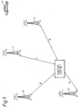
- FIG. 1 A simplified example of a quasi-synchronous, bi-directional radio system is shown schematically in Figure 1, where a control centre 1 is connected by fixed links (A,B,C,D) to radio transmitter sites 2,3,4,5.
- the radio transmitters may be referred to as transceivers, and in this specification the term "transmitter” includes transceivers).
- the system of this example is bi-directional permitting two way communication between a mobile station 6 and the control centre 1 via one of the radio transmitters 2, 3, 4, 5.
- radio transmitter (transceiver) sites all radiate the same signal on nominally the same radio channel.
- Such systems are suitable for wide area coverage over a limited number of radio channels, (sometimes only a single channel), and so are often adopted by police, fire and similar utility services.
- Geographical considerations, radio transmitter power restrictions, and other factors, often mean that it is not possible to achieve coverage of the area served by such services with a single radio transmitter site, so a multiple radio transmitter-site configuration of a quasi-synchronous or synchronous radio system is appropriate.
- the signals radiated from all radio transmitters are identical in all respects (and in particular, they are transmitted on the same frequency).
- the radio carrier frequencies of different radio transmitters are within a few Hertz of each other.
- the modulation imposed on the carrier is synchronous. This is necessary because in regions where the coverage of two neighbouring radio transmitters overlap, a mobile station will receive signals from both radio transmitters. In such circumstances the two signals must be sufficiently synchronous not to destructively interfere.
- a digital data network to provide the links, for example the Megastream (registered trade mark) service offered by British Telecommunications plc which provides customers with 2.048Mb/s digital paths between pairs of sites.
- Other examples of digital data networks which could be used are Kilostream (registered trade mark) and ISDN (Integrated Services Digital Network).
- the digital bearer can be used to carry a variety of traffic, including digital coded audio signals.
- the connection is not direct, but is provided through a trunk network, with customer access being via a local exchange.
- a characteristic of such networks is that they have the ability to re-route traffic to accommodate equipment failures, traffic fluctuations, etc.
- This dynamic re-routing facility is such that there is an uncertainty in the propagation delay which will be experienced by a signal travelling between two network terminations. The variation can be of the order of milliseconds.
- United States patents 4696051 and 5014344 both describe systems in which the differences in delay are measured against a common timing signal, the variations in delay relative to the signal then being compensated for in each individual link. However, these systems assume that the timing signal is itself synchronised with the digital data network. If this is not the case, the timing signal will itself be delayed by up to one bit period.
- the invention provides a radio system comprising : a central source of signals for transmission; a plurality of radio transmitters, each connected to the central source by a digital data transfer link, each having a respective transfer delay; means for injecting into a channel of a transfer link a test signal at intended predetermined times, means for determining the travel time of the test signal over a link by establishing the difference between arrival time and the intended predetermined time of transmission, and delay adjustment means for adjusting the transfer delay to at least one of the radio transmitters to equalise the transfer delays to the radio transmitters, so that signals originating from the central source can be transmitted from the radio transmitters substantially in time synchronism, and characterised in that there is correction means for measuring a transmit delay between the intended predetermined time of transmission from the central source of the test signal and the actual time of transmission of the test signal, and for sending the length of the transmit delay over the transfer link, so that the adjustment of transfer delay can be corrected to take account of the transmit delay.
- the invention provides a method of operating a radio system in which a signal for transmission is disseminated from a central source to a plurality of radio transmitters at separate sites, each connected to the central source by a digital data transfer link each having a respective transfer delay; the method comprising the steps of:
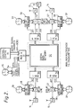
- the system of the preferred embodiment has a control centre 10, which is a source of and destination for signals, connected to a multiplexer A (51) and thence to a digital data network 52, shown exemplarily as a 2Mb/s Megastream network. Also connected to the data network are further multiplexers (Mux) B, C, D and E (56) at radio transmitters 13, 14, 15 & 16 positioned at various geographical locations.
- a test signal source 54, with associated clock 55, is also connected via the multiplexer 51 to the digital data network 52.
- the digital data network 52 serves four radio transmitter sites 53, each of which has a respective multiplexer 56, an output of which is connected to a variable delay line 57 which in turn is connected to the respective site radio transmitter, and a delay measuring unit 58 with associated clock 59, which unit is connected to receive an output from the respective multiplexer 56 and connected to provide a control output to the respective variable delay line 57.
- An analogue signal is fed over the digital network 52 to the various sites 13 to 16. These transmissions are multiplexed on the 2.048Mbps digital data stream (ie. Megastream), which connects each multiplexer in the network.
- the path length between each site and the control centre will vary according to the path taken.
- the preferred embodiment of the invention works to correct for these path differences, as follows.
- the test signal source 54 at the control centre 10 site applies a test signal (either analogue or digital) to the four test channels, 1-4.
- the time of arrival of the test signal is identified, and the corresponding propagation time from the control centre is determined. Additional delays are then built into the respective signal paths at each radio transmitter site, such that the aggregate delay between the control centre and any radio transmitter is the same.
- the maximum delay through digital networks is defined, and the aggregate delay should be chosen to accomodate this. Thus, for example, if the maximum delay through the data network were known to be 8ms, an aggregate delay of 10ms might be appropriate. Then if the delay to multiplexer 2 were 3ms, T2 would be set as 7ms, etc.
- This measurement and compensation process would be repeated at regular intervals to accomodate any changes in propagation delay brought about by re-routing within the digital data network.
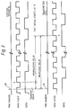
- the clock 55 associated with the control centre 10, and each of the clocks 59, at the various radio transmitter sites, synchronously generate a precise time marker, shown respectively as 60 and 61 in figure 3, at predetermined intervals, eg every minute or every second.
- the time marker is a pulse of 20 ⁇ s duration.
- a test signal is transmitted by the test signal source 54 to each of the radio transmitter sites via the digital data network 52.
- the delay between occurrence at the control centre 10 of the time marker 60 and the start of transmission of the test signal is termed the "transmit" delay.
- the transmission of the test signal is followed by a transmission from the control centre to each of the radio transmitter sites of the length of the transmit delay.
- This information is transmitted by means of a data packet comprising a 16 bit header forming the test signal followed by an 8 bit field containing the value of the length of the transmit delay.
- the delay measuring unit 58 starts a timer. These timers measure the delay before the test signal arrives at each site, and this measured delay is the propagation delay of the data network plus the transmit delay as shown in figure 3.
- the delay measuring unit 58 In order to determine the propagation delay itself the delay measuring unit 58 awaits the transmission of the length of the transmit delay, which follows each test signal, and then subtracts this transmit delay from the measured delay.
- the transmit delay is included in the delay calculation because the generation of the time markers is unlikely to be synchronous with the digital data network. This means that not taking the transmit delay into account could result in an error in the propagation delay of up to one bit period of the test signal channel. For example, if the test signal was transmitted via a 64k bit/s channel this would be 15.625 ⁇ s, which is a significant error.
- each delay measuring unit 58 calculates the delay between the control centre and each radio transmitter of a predetermined value (this value being the same at each radio transmitter site) which is known to exceed the longest possible transfer delay of the network.
- the additional delays inserted by the delay lines can be generated by any convenient method but are preferably generated by passing the digital voice samples carried by the data network through a shift register which operates at a constant rate, but whose length can be varied according to the delay required.
- a delay of N ⁇ s could be introduced by passing all audio signal samples through N stages of the shift register.
- the described embodiment employs separate channels for user data and the test signal.
- the same channel could be used for both, by using time division multiplexing of that channel.
- the transmit delay could be quite significant, being the period between occurrence of the time marker and the time slot for the test signal.
- the time markers 60, 61 can be generated by clocks 59 whose synchronism is maintained by any convenient method, but are preferable generated by clocks whose synchronism is maintained via a global positioning satellite system (GPS).
- GPS global positioning satellite system
Landscapes
- Engineering & Computer Science (AREA)
- Signal Processing (AREA)
- Mobile Radio Communication Systems (AREA)
- Radio Transmission System (AREA)
- Radio Relay Systems (AREA)
- Monitoring And Testing Of Transmission In General (AREA)
- Synchronisation In Digital Transmission Systems (AREA)
- Radar Systems Or Details Thereof (AREA)
- Transmitters (AREA)
- Cable Transmission Systems, Equalization Of Radio And Reduction Of Echo (AREA)
Claims (15)
- Système radio comprenant : une source centrale (10) de signaux destinée à une émission, une pluralité d'émetteurs radio (13, 14, 15, 16), chacun étant relié à la source centrale par une liaison de transfert de données numériques (1, 2, 3, 4, 5, 6, 7, 8, 9), chacune présentant un retard de transfert respectif, un moyen (54) destiné à injecter dans un canal d'une liaison de transfert un signal de test à des instants prédéterminés voulus, un moyen (58) destiné à déterminer le temps de transit du signal de test sur une liaison en établissant une différence entre l'instant d'arrivée et l'instant prédéterminé voulu de l'émission et un moyen de réglage de retard (57) destiné à régler le retard de transfert vers au moins l'un des émetteurs radio afin d'égaliser les retards de transfert vers les émetteurs radio, de sorte que des signaux ayant pour origine la source centrale (10) puissent être émis depuis les émetteurs radio pratiquement en synchronisme dans le temps,
caractérisé en ce qu'il existe un moyen de correction (54) destiné à mesurer un retard d'émission entre un instant prédéterminé voulu de l'émission depuis la source centrale (10) du signal de test et l'instant réel de l'émission du signal de test, et destiné à envoyer la longueur du retard d'émission sur la liaison de transfert, de sorte que le réglage du retard de transfert puisse être corrigé pour prendre en compte le retard d'émission. - Système radio selon la revendication 1, dans lequel le moyen de réglage de retard (57) peut être mis en oeuvre de façon à régler le retard de transfert de chacune des liaisons de transfert pour qu'il soit au moins égal au retard d'émission le plus long du système.
- Système radio selon la revendication 1 ou la revendication 2, dans lequel le moyen de réglage de retard (57) peut être mis en oeuvre pour régler le retard de transfert de chacune des liaisons de transfert pour qu'il soit égal à une limite prédéterminée.
- Système radio selon l'une quelconque des revendications précédentes, dans lequel le moyen de réglage de retard (57) comprend un registre à décalage de longueur variable.
- Système radio selon la revendication 4, dans lequel le registre à décalage fonctionne à une cadence constante.
- Système radio selon l'une quelconque des revendications précédentes, dans lequel chacun de la source centrale (10) et des émetteurs radio (13, 14, 15, 16) comporte une horloge (59) destinée à générer des repères de temps aux instants prédéterminés voulus.
- Système radio selon la revendication 6, dans lequel chacune des horloges (59) comporte un moyen destiné à la maintenir en synchronisme avec chacune des autres horloges par l'intermédiaire d'un satellite de positionnement global.
- Système radio selon la revendication 6 ou 7, dans lequel le moyen de correction (54) comprend un moyen destiné à mesurer le retard d'émission entre la génération d'un repère de temps et l'émission du signal de test.
- Système radio selon l'une quelconque des revendications précédentes comportant un moyen dans le centre de commande (10), destiné à mesurer le retard d'émission et à émettre le retard vers les émetteurs radio.
- Système radio selon l'une quelconque des revendications précédentes, dans lequel les émetteurs radio sont agencés pour émettre de façon quasi synchrone sur des fréquences porteuses différentes.
- Procédé de mise en oeuvre d'un système radio dans lequel un signal destiné à une émission est disséminé depuis une source centrale (10) vers une pluralité d'émetteurs radio (13, 14, 15, 16) au niveau de sites séparés, chacun étant relié à la source centrale par une liaison de transfert de données numériques, chacune présentant un retard de transfert respectif, le procédé comprenant les étapes consistant à :(a) injecter dans un canal d'une liaison de transfert un signal de test à des instants prédéterminés voulus,(b) déterminer le temps de transit du signal de test sur une liaison en établissant la différence entre l'instant d'arrivée et l'instant d'émission prédéterminé voulu.(c) mesurer un retard d'émission entre l'instant d'émission prédéterminé voulu et l'instant réel de l'émission du signal de test,(d) envoyer la longueur du retard d'émission sur la liaison de transfert, et(e) régler le retard de transfert vers au moins l'un des émetteurs radio (13, 14, 15, 16) afin d'égaliser les retards de transfert vers les émetteurs radio, de sorte que les signaux ayant pour origine la source centrale (10) puissent être émis depuis les émetteurs radio, pratiquement en synchronisme dans le temps,
- Procédé selon la revendication 11, dans lequel le retard de transfert de chacune des liaisons. de transfert est réglé pour être au moins égal au retard d'émission le plus long du système.
- Procédé selon la revendication 11 ou la revendication 12, dans lequel le retard de transfert de chacune des liaisons de transfert est réglé pour être égal à une limite prédéterminée.
- Procédé selon la revendication 11, 12 ou 13, dans lequel la longueur du retard d'émission est mesurée au niveau de la source centrale (10) et est émise vers les émetteurs radio (13, 14, 15, 16) après le signal de test.
- Procédé selon la revendication 11, 12, 13 ou 14, dans lequel les émetteurs radio émettent de façon quasi synchrone sur des fréquences porteuses différentes.
Applications Claiming Priority (2)
| Application Number | Priority Date | Filing Date | Title |
|---|---|---|---|
| GB919111313A GB9111313D0 (en) | 1991-05-24 | 1991-05-24 | Radio system |
| GB9111313 | 1991-05-24 |
Publications (2)
| Publication Number | Publication Date |
|---|---|
| EP0515214A1 EP0515214A1 (fr) | 1992-11-25 |
| EP0515214B1 true EP0515214B1 (fr) | 1997-09-03 |
Family
ID=10695594
Family Applications (2)
| Application Number | Title | Priority Date | Filing Date |
|---|---|---|---|
| EP92304673A Expired - Lifetime EP0515214B1 (fr) | 1991-05-24 | 1992-05-22 | Système de transmission radio avec mesure et ajustement de la durée de transfert |
| EP92910360A Pending EP0586434A1 (fr) | 1991-05-24 | 1992-05-22 | Systeme radio effectuant la mesure et le reglage des retards de transfert |
Family Applications After (1)
| Application Number | Title | Priority Date | Filing Date |
|---|---|---|---|
| EP92910360A Pending EP0586434A1 (fr) | 1991-05-24 | 1992-05-22 | Systeme radio effectuant la mesure et le reglage des retards de transfert |
Country Status (17)
| Country | Link |
|---|---|
| US (1) | US5483677A (fr) |
| EP (2) | EP0515214B1 (fr) |
| JP (1) | JPH06508727A (fr) |
| AT (1) | ATE157824T1 (fr) |
| AU (1) | AU1791892A (fr) |
| CA (1) | CA2103442C (fr) |
| DE (1) | DE69221938T2 (fr) |
| DK (1) | DK0515214T3 (fr) |
| ES (1) | ES2107504T3 (fr) |
| GB (1) | GB9111313D0 (fr) |
| HK (1) | HK1002944A1 (fr) |
| IE (1) | IE80553B1 (fr) |
| IN (1) | IN182881B (fr) |
| NZ (1) | NZ242860A (fr) |
| SG (1) | SG47685A1 (fr) |
| WO (1) | WO1992021184A1 (fr) |
| ZA (1) | ZA923760B (fr) |
Families Citing this family (14)
| Publication number | Priority date | Publication date | Assignee | Title |
|---|---|---|---|---|
| US5361398A (en) * | 1993-01-29 | 1994-11-01 | Motorola, Inc. | Method and apparatus for transmission path delay measurements using adaptive demodulation |
| US5481258A (en) * | 1993-08-11 | 1996-01-02 | Glenayre Electronics, Inc. | Method and apparatus for coordinating clocks in a simulcast network |
| AU4607996A (en) * | 1994-12-27 | 1996-07-19 | Ericsson Inc. | Simulcast resynchronisation improvement using global positioning system |
| US5742907A (en) * | 1995-07-19 | 1998-04-21 | Ericsson Inc. | Automatic clear voice and land-line backup alignment for simulcast system |
| US6011977A (en) * | 1995-11-30 | 2000-01-04 | Ericsson Inc. | RF simulcasting system with dynamic wide-range automatic synchronization |
| US5991309A (en) * | 1996-04-12 | 1999-11-23 | E.F. Johnson Company | Bandwidth management system for a remote repeater network |
| WO1997039535A2 (fr) * | 1996-04-12 | 1997-10-23 | E.F. Johnson Company | Systeme de gestion des largeurs de bande pour un reseau a repeteurs tele-alimentes |
| US6049720A (en) * | 1996-04-12 | 2000-04-11 | Transcrypt International / E.F. Johnson Company | Link delay calculation and compensation system |
| US5896560A (en) * | 1996-04-12 | 1999-04-20 | Transcrypt International/E. F. Johnson Company | Transmit control system using in-band tone signalling |
| US6215767B1 (en) * | 1997-04-25 | 2001-04-10 | Lucent Technologies Inc. | Quality of service adjustment and traffic shaping on a multiple access network |
| US5953384A (en) * | 1997-06-05 | 1999-09-14 | Motorola, Inc. | Automatic measurement of GPS cable delay time |
| TW507428B (en) * | 1999-03-31 | 2002-10-21 | Harris Corp | Method and system for extending broadcast coverage on a single frequency network |
| JP2001156705A (ja) * | 1999-11-30 | 2001-06-08 | Nec Shizuoka Ltd | 移動通信システム及び無線基地局間同期制御方法 |
| DE102006019475B4 (de) * | 2006-04-26 | 2008-08-28 | Nokia Siemens Networks Gmbh & Co.Kg | Verfahren zur Synchronisation von Baugruppen einer Basisstation |
Family Cites Families (5)
| Publication number | Priority date | Publication date | Assignee | Title |
|---|---|---|---|---|
| US4696052A (en) * | 1985-12-31 | 1987-09-22 | Motorola Inc. | Simulcast transmitter apparatus having automatic synchronization capability |
| US4696051A (en) * | 1985-12-31 | 1987-09-22 | Motorola Inc. | Simulcast transmission system having automtic synchronization |
| JP2615753B2 (ja) * | 1988-02-10 | 1997-06-04 | 日本電気株式会社 | 自動位相調整方式 |
| JP2599613B2 (ja) * | 1988-03-24 | 1997-04-09 | 東北電力 株式会社 | 人工衛星を利用した送電線故障点標定システム |
| US5014344A (en) * | 1990-03-19 | 1991-05-07 | Motorola, Inc. | Method for synchronizing the transmissions in a simulcast transmission system |
-
1991
- 1991-05-24 GB GB919111313A patent/GB9111313D0/en active Pending
-
1992
- 1992-05-22 NZ NZ242860A patent/NZ242860A/en unknown
- 1992-05-22 WO PCT/GB1992/000935 patent/WO1992021184A1/fr not_active Ceased
- 1992-05-22 ZA ZA923760A patent/ZA923760B/xx unknown
- 1992-05-22 DE DE69221938T patent/DE69221938T2/de not_active Expired - Fee Related
- 1992-05-22 SG SG1996003723A patent/SG47685A1/en unknown
- 1992-05-22 ES ES92304673T patent/ES2107504T3/es not_active Expired - Lifetime
- 1992-05-22 DK DK92304673.4T patent/DK0515214T3/da active
- 1992-05-22 US US08/142,399 patent/US5483677A/en not_active Expired - Fee Related
- 1992-05-22 CA CA002103442A patent/CA2103442C/fr not_active Expired - Fee Related
- 1992-05-22 JP JP4510514A patent/JPH06508727A/ja active Pending
- 1992-05-22 IN IN312MA1992 patent/IN182881B/en unknown
- 1992-05-22 AT AT92304673T patent/ATE157824T1/de not_active IP Right Cessation
- 1992-05-22 EP EP92304673A patent/EP0515214B1/fr not_active Expired - Lifetime
- 1992-05-22 AU AU17918/92A patent/AU1791892A/en not_active Abandoned
- 1992-05-22 EP EP92910360A patent/EP0586434A1/fr active Pending
- 1992-07-01 IE IE921666A patent/IE80553B1/en not_active IP Right Cessation
-
1998
- 1998-02-26 HK HK98101506A patent/HK1002944A1/en not_active IP Right Cessation
Also Published As
| Publication number | Publication date |
|---|---|
| ES2107504T3 (es) | 1997-12-01 |
| ATE157824T1 (de) | 1997-09-15 |
| EP0515214A1 (fr) | 1992-11-25 |
| HK1002944A1 (en) | 1998-09-25 |
| SG47685A1 (en) | 1998-04-17 |
| IN182881B (fr) | 1999-07-31 |
| IE80553B1 (en) | 1998-09-09 |
| EP0586434A1 (fr) | 1994-03-16 |
| AU1791892A (en) | 1992-12-30 |
| US5483677A (en) | 1996-01-09 |
| GB9111313D0 (en) | 1991-07-17 |
| IE921666A1 (en) | 1992-12-02 |
| CA2103442A1 (fr) | 1992-11-25 |
| NZ242860A (en) | 1994-11-25 |
| JPH06508727A (ja) | 1994-09-29 |
| ZA923760B (en) | 1993-01-27 |
| DE69221938D1 (de) | 1997-10-09 |
| CA2103442C (fr) | 1998-09-22 |
| DE69221938T2 (de) | 1998-02-05 |
| WO1992021184A1 (fr) | 1992-11-26 |
| DK0515214T3 (da) | 1998-04-14 |
Similar Documents
| Publication | Publication Date | Title |
|---|---|---|
| US5245634A (en) | Base-site synchronization in a communication system | |
| US5280629A (en) | Technique for measuring channel delay | |
| CA2103442C (fr) | Systeme radio a mesure et a reglage du retard de transfert | |
| EP2067287B1 (fr) | Système de diffusion simultanée à compensation de retard automatique et procédé | |
| US5959982A (en) | Method and apparatus for adapting a time division duplex timing device for propagation delay | |
| US5423058A (en) | Simulcast transmission system with selective call tones | |
| HK1002944B (en) | Radio system with measurement and adjustment of transfer delay | |
| KR20020020792A (ko) | 순차적인 동기 네트워크를 위한 방법 및 장치 | |
| CA2168017A1 (fr) | Methode et appareil pour coordonner les horloges dans un reseau de diffusion simultanee | |
| US5873044A (en) | Method and apparatus in a radio communication system for synchronizing transmissions while maintaining full user traffic | |
| EP0606236A4 (en) | Simulcast synchronization and equalization system and method therefor. | |
| EP0653845B1 (fr) | Procédé et dispositif pour synchroniser la fréquence d'emission de deux stations de base | |
| WO1992013417A1 (fr) | Systeme de transmission a diffusion simultanee presentant des debuts de transmission predetermines | |
| KR100281098B1 (ko) | 이동통신시스템의 내부 네트워크를 이용하는 시스템 동기장치 | |
| EP0300649B1 (fr) | Synchronisation de bit pour des réseaux optiques | |
| US5590140A (en) | Clock recovery extrapolation | |
| KR100201421B1 (ko) | 무선 호출망을 이용한 이동 통신 신호 제공 시스템 | |
| JPH0229043A (ja) | 位相較正方式 | |
| JPH01240025A (ja) | 集線分配方式 | |
| JPS594905B2 (ja) | 位相調整方式 | |
| JP2002082188A (ja) | 衛星双方向時刻比較方法及び同装置 | |
| HK1106887B (en) | Base station synchronization for wireless communication systems | |
| HK1106887A1 (en) | Base station synchronization for wireless communication systems |
Legal Events
| Date | Code | Title | Description |
|---|---|---|---|
| PUAI | Public reference made under article 153(3) epc to a published international application that has entered the european phase |
Free format text: ORIGINAL CODE: 0009012 |
|
| AK | Designated contracting states |
Kind code of ref document: A1 Designated state(s): PT |
|
| 17P | Request for examination filed |
Effective date: 19930518 |
|
| 17Q | First examination report despatched |
Effective date: 19960422 |
|
| RBV | Designated contracting states (corrected) |
Designated state(s): AT BE CH DE DK ES FR GB GR IT LI LU NL PT SE |
|
| XX | Miscellaneous (additional remarks) |
Free format text: VERBUNDEN MIT 92910360.4/0586434 (EUROPAEISCHE ANMELDENUMMER/VEROEFFENTLICHUNGSNUMMER) DURCH ENTSCHEIDUNG VOM 12.08.96. |
|
| GRAG | Despatch of communication of intention to grant |
Free format text: ORIGINAL CODE: EPIDOS AGRA |
|
| GRAH | Despatch of communication of intention to grant a patent |
Free format text: ORIGINAL CODE: EPIDOS IGRA |
|
| GRAH | Despatch of communication of intention to grant a patent |
Free format text: ORIGINAL CODE: EPIDOS IGRA |
|
| GRAA | (expected) grant |
Free format text: ORIGINAL CODE: 0009210 |
|
| AK | Designated contracting states |
Kind code of ref document: B1 Designated state(s): AT BE CH DE DK ES FR GB GR IT LI LU NL PT SE |
|
| PG25 | Lapsed in a contracting state [announced via postgrant information from national office to epo] |
Ref country code: GR Free format text: LAPSE BECAUSE OF FAILURE TO SUBMIT A TRANSLATION OF THE DESCRIPTION OR TO PAY THE FEE WITHIN THE PRESCRIBED TIME-LIMIT Effective date: 19970903 Ref country code: AT Effective date: 19970903 |
|
| REF | Corresponds to: |
Ref document number: 157824 Country of ref document: AT Date of ref document: 19970915 Kind code of ref document: T |
|
| XX | Miscellaneous (additional remarks) |
Free format text: VERBUNDEN MIT 92910360.4/0586434 (EUROPAEISCHE ANMELDENUMMER/VEROEFFENTLICHUNGSNUMMER) DURCH ENTSCHEIDUNG VOM 12.08.96. |
|
| REG | Reference to a national code |
Ref country code: CH Ref legal event code: NV Representative=s name: JACOBACCI & PERANI S.A. Ref country code: CH Ref legal event code: EP |
|
| ITF | It: translation for a ep patent filed | ||
| REF | Corresponds to: |
Ref document number: 69221938 Country of ref document: DE Date of ref document: 19971009 |
|
| REG | Reference to a national code |
Ref country code: ES Ref legal event code: FG2A Ref document number: 2107504 Country of ref document: ES Kind code of ref document: T3 |
|
| REG | Reference to a national code |
Ref country code: PT Ref legal event code: SC4A Free format text: AVAILABILITY OF NATIONAL TRANSLATION Effective date: 19970919 |
|
| ET | Fr: translation filed | ||
| REG | Reference to a national code |
Ref country code: DK Ref legal event code: T3 |
|
| PG25 | Lapsed in a contracting state [announced via postgrant information from national office to epo] |
Ref country code: LU Free format text: LAPSE BECAUSE OF NON-PAYMENT OF DUE FEES Effective date: 19980522 |
|
| PG25 | Lapsed in a contracting state [announced via postgrant information from national office to epo] |
Ref country code: SE Free format text: LAPSE BECAUSE OF NON-PAYMENT OF DUE FEES Effective date: 19980523 Ref country code: ES Free format text: LAPSE BECAUSE OF EXPIRATION OF PROTECTION Effective date: 19980523 |
|
| PG25 | Lapsed in a contracting state [announced via postgrant information from national office to epo] |
Ref country code: LI Free format text: LAPSE BECAUSE OF NON-PAYMENT OF DUE FEES Effective date: 19980531 Ref country code: DK Free format text: LAPSE BECAUSE OF NON-PAYMENT OF DUE FEES Effective date: 19980531 Ref country code: CH Free format text: LAPSE BECAUSE OF NON-PAYMENT OF DUE FEES Effective date: 19980531 Ref country code: BE Free format text: LAPSE BECAUSE OF NON-PAYMENT OF DUE FEES Effective date: 19980531 |
|
| PLBE | No opposition filed within time limit |
Free format text: ORIGINAL CODE: 0009261 |
|
| STAA | Information on the status of an ep patent application or granted ep patent |
Free format text: STATUS: NO OPPOSITION FILED WITHIN TIME LIMIT |
|
| 26N | No opposition filed | ||
| BERE | Be: lapsed |
Owner name: BRITISH TELECOMMUNICATIONS P.L.C. Effective date: 19980531 |
|
| PG25 | Lapsed in a contracting state [announced via postgrant information from national office to epo] |
Ref country code: PT Free format text: LAPSE BECAUSE OF NON-PAYMENT OF DUE FEES Effective date: 19981130 |
|
| REG | Reference to a national code |
Ref country code: CH Ref legal event code: PL |
|
| EUG | Se: european patent has lapsed |
Ref document number: 92304673.4 |
|
| REG | Reference to a national code |
Ref country code: PT Ref legal event code: MM4A Free format text: LAPSE DUE TO NON-PAYMENT OF FEES Effective date: 19981130 |
|
| REG | Reference to a national code |
Ref country code: ES Ref legal event code: FD2A Effective date: 20000201 |
|
| REG | Reference to a national code |
Ref country code: DK Ref legal event code: EBP |
|
| PGFP | Annual fee paid to national office [announced via postgrant information from national office to epo] |
Ref country code: FR Payment date: 20000411 Year of fee payment: 9 |
|
| PGFP | Annual fee paid to national office [announced via postgrant information from national office to epo] |
Ref country code: NL Payment date: 20000425 Year of fee payment: 9 Ref country code: DE Payment date: 20000425 Year of fee payment: 9 |
|
| PG25 | Lapsed in a contracting state [announced via postgrant information from national office to epo] |
Ref country code: NL Free format text: LAPSE BECAUSE OF NON-PAYMENT OF DUE FEES Effective date: 20011201 |
|
| REG | Reference to a national code |
Ref country code: GB Ref legal event code: IF02 |
|
| PG25 | Lapsed in a contracting state [announced via postgrant information from national office to epo] |
Ref country code: FR Free format text: LAPSE BECAUSE OF NON-PAYMENT OF DUE FEES Effective date: 20020131 |
|
| NLV4 | Nl: lapsed or anulled due to non-payment of the annual fee |
Effective date: 20011201 |
|
| PG25 | Lapsed in a contracting state [announced via postgrant information from national office to epo] |
Ref country code: DE Free format text: LAPSE BECAUSE OF NON-PAYMENT OF DUE FEES Effective date: 20020301 |
|
| PGFP | Annual fee paid to national office [announced via postgrant information from national office to epo] |
Ref country code: GB Payment date: 20020417 Year of fee payment: 11 |
|
| PG25 | Lapsed in a contracting state [announced via postgrant information from national office to epo] |
Ref country code: GB Free format text: LAPSE BECAUSE OF NON-PAYMENT OF DUE FEES Effective date: 20030522 |
|
| GBPC | Gb: european patent ceased through non-payment of renewal fee |
Effective date: 20030522 |
|
| PG25 | Lapsed in a contracting state [announced via postgrant information from national office to epo] |
Ref country code: IT Free format text: LAPSE BECAUSE OF NON-PAYMENT OF DUE FEES;WARNING: LAPSES OF ITALIAN PATENTS WITH EFFECTIVE DATE BEFORE 2007 MAY HAVE OCCURRED AT ANY TIME BEFORE 2007. THE CORRECT EFFECTIVE DATE MAY BE DIFFERENT FROM THE ONE RECORDED. Effective date: 20050522 |