EP0515230A2 - Befestigungsvorrichtung für drehende Werkstückeinheit - Google Patents
Befestigungsvorrichtung für drehende Werkstückeinheit Download PDFInfo
- Publication number
- EP0515230A2 EP0515230A2 EP92304697A EP92304697A EP0515230A2 EP 0515230 A2 EP0515230 A2 EP 0515230A2 EP 92304697 A EP92304697 A EP 92304697A EP 92304697 A EP92304697 A EP 92304697A EP 0515230 A2 EP0515230 A2 EP 0515230A2
- Authority
- EP
- European Patent Office
- Prior art keywords
- flange
- spindle
- outer part
- inner part
- bearing
- Prior art date
- Legal status (The legal status is an assumption and is not a legal conclusion. Google has not performed a legal analysis and makes no representation as to the accuracy of the status listed.)
- Granted
Links
- 239000011248 coating agent Substances 0.000 claims description 8
- 238000000576 coating method Methods 0.000 claims description 8
- 230000002093 peripheral effect Effects 0.000 claims description 5
- 230000009467 reduction Effects 0.000 claims description 5
- ZOKXTWBITQBERF-UHFFFAOYSA-N Molybdenum Chemical compound [Mo] ZOKXTWBITQBERF-UHFFFAOYSA-N 0.000 claims description 3
- 239000004809 Teflon Substances 0.000 claims description 3
- 229920006362 Teflon® Polymers 0.000 claims description 3
- 229910052750 molybdenum Inorganic materials 0.000 claims description 3
- 239000011733 molybdenum Substances 0.000 claims description 3
- 238000007789 sealing Methods 0.000 claims 1
- 230000007246 mechanism Effects 0.000 abstract description 2
- 230000008859 change Effects 0.000 description 3
- 238000005096 rolling process Methods 0.000 description 2
- 239000011449 brick Substances 0.000 description 1
- ZPUCINDJVBIVPJ-LJISPDSOSA-N cocaine Chemical compound O([C@H]1C[C@@H]2CC[C@@H](N2C)[C@H]1C(=O)OC)C(=O)C1=CC=CC=C1 ZPUCINDJVBIVPJ-LJISPDSOSA-N 0.000 description 1
- 230000000295 complement effect Effects 0.000 description 1
- 238000005520 cutting process Methods 0.000 description 1
- 239000000428 dust Substances 0.000 description 1
- 238000003754 machining Methods 0.000 description 1
- 239000000463 material Substances 0.000 description 1
- 230000004048 modification Effects 0.000 description 1
- 238000012986 modification Methods 0.000 description 1
- 238000005121 nitriding Methods 0.000 description 1
- BFKJFAAPBSQJPD-UHFFFAOYSA-N tetrafluoroethene Chemical group FC(F)=C(F)F BFKJFAAPBSQJPD-UHFFFAOYSA-N 0.000 description 1
Images

Classifications
-
- B—PERFORMING OPERATIONS; TRANSPORTING
- B24—GRINDING; POLISHING
- B24B—MACHINES, DEVICES, OR PROCESSES FOR GRINDING OR POLISHING; DRESSING OR CONDITIONING OF ABRADING SURFACES; FEEDING OF GRINDING, POLISHING, OR LAPPING AGENTS
- B24B45/00—Means for securing grinding wheels on rotary arbors
- B24B45/006—Quick mount and release means for disc-like wheels, e.g. on power tools
Definitions
- the present invention relates to a device for clamping a rotary tool element which is mounted on a sprindle of e.g. an electric power driven tool or a pneumatic tool such as a portable grinder.
- FIG. 5 A conventional device for clamping a rotary tool element of a power driven tool is shown in FIG. 5 and has a first flange 8A and a second flange 9A.
- the first flange 8A is fitted on a spindle 4A and is rotatable with the spindle 4A.
- the second flange 9A is screwed on the spindle 4A.
- the rotary blade 7A is fitted on the spindle 4A with its one end surface abutting on the the first flange 8A.
- the second flange 9A is thereafter screwed on a threaded portion 6A of the spindle 4A and is tightened to abut on the other end surface of the rotary blade 7A.
- the rotary blade 7A can be removably clamped between the first flange 8A and the second flange 9A.
- the rotary blade 7A clamped between the first flange 8A and the second flange 9A may be slided or rotated by the load applied thereto during machining operation of a work in the same direction as that for fastening the second flange 9A.
- the second flange 9A is further tightened to increase the clamping force.
- the second flange 9A is loosened and removed from the spindle 4A.
- the force (torque) for loosening the second flange 9A is influenced by the frictional force between the second flange 9A and the spindle 4A produced at the threaded portion 6A, and that between the second flange 9A and the rotary blade 7A as well as that between the rotary blade 7A and the first flange 8A. Therefore, in the cutting operation of a work made especially of relatively hard material such as a brick, substantial load is applied to the rotary blade 7A, resulting in that the second flange 9A is firmly tightened. This may cause the rotary blade 7A to be worn out earlier.
- the second flange 9A normally includes a plurality of holes for engagement with pins of a wrench which is normally attached to this kind of power driven tool, and the second flange 9A is tightened or loosened through rotation by the wrench.
- the rotation of the second flange 9A is frequently difficult.
- the wrench is forcibly rotated, the pins or the wrench may be damaged or the holes of the second flange 9A for engagement with the pins may be deformed or enlarged to cause unreliable engagement with the pin, and consequently the device cannot be used further.
- an object of the present invention to provide a device for clamping a rotary tool element of e.g. an electric power driven tool or a pneumatic tool which permits to easily loosen a movable flange in a simple manner for change of the rotary toot element or other operations, while ensuring reliable clamping of the rotary tool element.
- a rotary tool element e.g. an electric power driven tool or a pneumatic tool which permits to easily loosen a movable flange in a simple manner for change of the rotary toot element or other operations, while ensuring reliable clamping of the rotary tool element.
- a device for axially clamping a rotary tool element fitted on a spindle of a power driven tool or the like comprising: a first flange mounted on the spindle and having an inner part rotatable with the spindle and an outer part rotatable relative to the inner part about a longitudinal axis of the spindle through a bearing, the outer part having a first surface for abutting on one end of the rotary tool element; an engaging mechanism disposed between the inner part and the outer part for limiting rotation of the outer part relative to the inner part within a predetermined angle; and a second flange threadably engaged with a threaded portion of the spindle and having a second surface for abutting on the other end of the rotary tool element, the second flange being operable to be tightened for clamping the rotary tool element between the second flange and the outer part of the first flange.
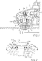
- FIG. 1 there is shown a sectional view of a lower part of a portable power driven grinder having a body G.
- the body G includes a gear box 1 into which an output shaft 2 of a motor (not shown) extends.
- a spindle 4 is rotatably supported by bearings 5a and 5b mounted on the gear box 1 and is connected to the output shaft 2 through reduction gears 3.
- One end of the spindle 4 extends downwardly from the bottom of the gear box 1 and is formed with a threaded portion 6.
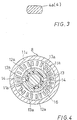
- a flange portion 4a is formed adjacent above the threaded portion 6 and is chamfered at both sides diametrically opposed to each other as shown in FIG. 3.
- a device for clamping a disc-like grinding wheel 7 includes a first flange 8 and a second flange 9.
- the first flange 8 is axially displaceably mounted on the spindle 4 and is in engagement with the flange portion 4a for rotation with the spindle 4.
- the second flange 9 is screwed on the threaded portion 6 and includes a plurality of holes 10 for engagement with a wrench (not shown) which applies rotation to the second flange 9 to tighten the same for clamping the grinding wheel 7 between the first flange 8 and the second flange 9.
- the first flange 8 is separated into a cup-shaped inner part 11 and an annular outer part 12 to form a space therebetween for accommodating an annular needle bearing 13 having a plurality of needle rollers 13a disposed in a radial direction and spaced from each other in a circumferential direction.
- a pair of partly annular protrusions 11a and a pair of partly annular protrusions 12a similar thereto are formed with the inner part 11 and the outer part 12, respectively.
- the annular protrusions 11a and the annular protrusions 12a extend in an axial direction toward the outer part 12 and the inner part 11, respectively, and are disposed complementary to each other.
- the pair of the annular protrusions 12a as well as the pair of the annular protrusions 11a are diametrically opposed to each other in a symmetrical manner to form a pair of equivalent clearances therebetween.
- Each of the protrusions 11a and 12a has a circumferential length shorter than that of each of the clearances, so that the outer part 12 can be rotated relative to the inner part 11 within a predetermined range.
- a gap 14 is formed between each of the annular protrusions 12a and each of the annular protrusions 11a disposed in a clockwise direction thereof.
- the inner part 11 of the first flange 8 has at its upper portion a recess 11b which corresponds to the flange portion 4a of the spindle 4 and is in engagement therewith, so that the inner part 11 can rotate with the spindle 4. Further, the inner part 11 has a flanged outer peripheral portion 11c, and the needle bearing 13 is received between the annular protrusions 11a and the outer peripheral portion 11c.
- the outer part 12 includes a boss portion 12b and a lower planer surface 12c.
- the grinding wheel 7 is supported by the boss portion 12b with its upper surface abutting on the planer surface 12c.
- An O-ring 15 is inserted between the outer peripheral portion 11c of the inner part 11 and the outer peripheral surface of the outer part 12. Further, a rubber annular ring 16 is interposed between the inner part 11 and the outer part 12 at a position adjacent the spindle 4. Thus, the O-ring 15 and the annular ring 16 function to seal the space formed between the inner part 11 and the outer part 12 from the outside so as to prevent entry of dust to the space. The O-ring 15 further functions to prevent removal of the outer part 12 from the inner part 11.
- the surface of the threaded portion 6 of the spindle 4 may be coated with a tetrafluoroethylene or Teflon coating for reducing frictional force with the second flange 9.
- the entire surface of the second flange 9 may be coated with a molybdenum-based coating or is soft-nitrided for reduction of frictional force.
- the outer part 12 of the first flange 8 as well as the grinding wheel 7 may rotate with the second flange 9.
- the rotation of the outer part 12 is, however, prevented when the protrusion 12a of the outer part 12 is engaged with the protrusion 11a of the inner part 11 as shown in FIG. 4, and the outer part 12 cannot be rotated further. Therefore, the grinding wheel 7 can be clamped between the outer part 12 of the second flange 9 and the first flange 8 as the second flange 9 is further tightened.
- the second flange 9 is rotated in a reverse direction so as to be loosened and is thereafter removed from the spindle 4.
- the needle roller bearing 13 reduces the frictional force between the inner part 11 and the outer part 12 of the first flange 8 to become smaller than that between the outer part 12 and the grinding wheel 7 as well as that between the grinding wheel 7 and the second flange 9. Therefore, the outer part 12, the grinding wheel 7 and the second flange 9 may be rotated together relative to the inner part 11 of the first flange 8 at the beginning of the reverse rotation of the second flange 9.
- the rotational force (torque) depends on the frictional force between the threaded portion 6 of the spindle 4 and the second flange 9 and the frictional force between the inner part 11 and the outer part 12 of the first flange 8, and since such frictional force between the inner part 11 and the outer part 12 is relatively small because of rolling friction, the force (torque) for rotation of the second flange 9 may be reduced.
- the needle roller bearing 13 is interposed between the inner part 11 and the outer part 12 of the first flange, any other rolling bearings other than the needle roller bearing 13 can be used for permitting rotation of the outer part 12 relative to the inner part 11.
Landscapes
- Engineering & Computer Science (AREA)
- Mechanical Engineering (AREA)
- Constituent Portions Of Griding Lathes, Driving, Sensing And Control (AREA)
- Polishing Bodies And Polishing Tools (AREA)
- Finish Polishing, Edge Sharpening, And Grinding By Specific Grinding Devices (AREA)
Applications Claiming Priority (2)
| Application Number | Priority Date | Filing Date | Title |
|---|---|---|---|
| JP11728691A JP3244718B2 (ja) | 1991-05-22 | 1991-05-22 | 回転工具における回転刃具の固止装置 |
| JP117286/91 | 1991-05-22 |
Publications (3)
| Publication Number | Publication Date |
|---|---|
| EP0515230A2 true EP0515230A2 (de) | 1992-11-25 |
| EP0515230A3 EP0515230A3 (en) | 1993-02-03 |
| EP0515230B1 EP0515230B1 (de) | 1995-11-15 |
Family
ID=14707987
Family Applications (1)
| Application Number | Title | Priority Date | Filing Date |
|---|---|---|---|
| EP92304697A Expired - Lifetime EP0515230B1 (de) | 1991-05-22 | 1992-05-22 | Befestigungsvorrichtung für drehende Werkstückeinheit |
Country Status (4)
| Country | Link |
|---|---|
| US (1) | US5259145A (de) |
| EP (1) | EP0515230B1 (de) |
| JP (1) | JP3244718B2 (de) |
| DE (1) | DE69206045T2 (de) |
Cited By (5)
| Publication number | Priority date | Publication date | Assignee | Title |
|---|---|---|---|---|
| EP0806269A1 (de) * | 1996-05-07 | 1997-11-12 | Atlas Copco Tools Ab | Tragbares Schleifwerkzeug |
| AT403445B (de) * | 1993-07-22 | 1998-02-25 | Ringhofer Ewald | Vorrichtung zum lösen und gegebenenfalls zum befestigen einer trenn- oder schleifscheibe |
| WO1999004928A3 (de) * | 1997-07-26 | 1999-04-15 | Schaeffler Waelzlager Ohg | Spanneinrichtung zum lösbaren befestigen eines scheibenförmigen werkzeugs |
| WO2001002137A1 (de) * | 1999-07-06 | 2001-01-11 | Stefan Fenchel | Vorrichtung zum leichteren lösen einer schraubverbindung |
| WO2011124458A1 (de) * | 2010-04-09 | 2011-10-13 | Schaeffler Technologies Gmbh & Co. Kg | Tragbares motorwerkzeug mit einer unwuchtausgleichsvorrichtung und einer spannvorrichtung für ein rotationssymmetrisches arbeitsmittel |
Families Citing this family (22)
| Publication number | Priority date | Publication date | Assignee | Title |
|---|---|---|---|---|
| US5464365A (en) * | 1991-09-21 | 1995-11-07 | Robert Bosch Gmbh | Motor-driven hand-held machine tool |
| JPH0768464A (ja) * | 1993-09-03 | 1995-03-14 | Hitachi Koki Co Ltd | 固定側フランジ |
| DE4336620C2 (de) * | 1993-10-27 | 1997-07-03 | Fein C & E | Elektrowerkzeug mit einer nur bei ausgeschaltetem Motor betätigbaren Spannvorrichtung |
| JP3333627B2 (ja) * | 1994-04-06 | 2002-10-15 | 株式会社マキタ | 回転研削工具のツール固止装置 |
| US5871322A (en) * | 1994-12-22 | 1999-02-16 | Power Tool Holders Incorporated | Clamp screw |
| US6273659B1 (en) | 1997-02-17 | 2001-08-14 | Power Tool Holders Incorporated | Locking mechanism for a rotary working member |
| EP0981421B1 (de) * | 1997-05-13 | 2000-10-18 | August Heinr. Schmidt GmbH & Co. KG. Maschinenfabrik | Schleifscheibe zur bearbeitung von metallkreissägeblättern |
| US6050741A (en) * | 1998-01-30 | 2000-04-18 | Power Tool Holders Incorporated | Tool clamping device |
| US6179512B1 (en) | 1998-05-29 | 2001-01-30 | Power Tool Holders Incorporated | Collet nut |
| AT409469B (de) * | 1998-11-10 | 2002-08-26 | Swarovski Tyrolit Schleif | Spanneinrichtung für schleifscheiben |
| US7013987B2 (en) * | 2000-09-08 | 2006-03-21 | Black & Decker | Clutch assembly and clamp mechanism for rotary tool disc |
| US6645058B2 (en) | 2000-11-30 | 2003-11-11 | Black & Decker Inc. | Clamp mechanism for rotary tool disc |
| ATE327863T1 (de) * | 2002-01-10 | 2006-06-15 | Black & Decker Inc | Getriebegehäuse |
| US20050192585A1 (en) * | 2004-02-27 | 2005-09-01 | Medtronic, Inc. | Surgical saw collet with closed drive ring |
| DE102004020982A1 (de) * | 2004-04-23 | 2005-11-17 | C. & E. Fein Gmbh | Kraftgetriebenes Handwerkzeug mit Spanneinrichtung für ein Werkzeug |
| US8087977B2 (en) | 2005-05-13 | 2012-01-03 | Black & Decker Inc. | Angle grinder |
| DE102005054578A1 (de) * | 2005-11-16 | 2007-05-24 | Robert Bosch Gmbh | Trennscheibe |
| US9010310B2 (en) * | 2009-11-30 | 2015-04-21 | Heavy Equipment Manufacturing | Independently supported concrete saw apparatus and method |
| US9127418B2 (en) * | 2013-08-19 | 2015-09-08 | Roger Bockes | Independently supported concrete saw apparatus and method |
| CN105538052B (zh) * | 2016-02-24 | 2017-12-29 | 深圳市金洲精工科技股份有限公司 | 旋转切削工具磨削及夹持装置 |
| US10818450B2 (en) | 2017-06-14 | 2020-10-27 | Black & Decker Inc. | Paddle switch |
| CN113261862A (zh) * | 2021-06-18 | 2021-08-17 | 唐锋机电科技(深圳)有限公司 | 一种具有一体式双盘结构的研磨机及其装配方法 |
Family Cites Families (17)
| Publication number | Priority date | Publication date | Assignee | Title |
|---|---|---|---|---|
| US2416141A (en) * | 1943-11-03 | 1947-02-18 | Jose Da Silva | Diamond polishing disc supporting spindle |
| US2572042A (en) * | 1948-07-13 | 1951-10-23 | Charles A Martin | Means for mounting cutting blades on shafts |
| CH449931A (de) * | 1966-12-06 | 1968-01-15 | Perles Elektrowerkzeuge & Moto | Spannvorrichtung für das Blatt einer Handkreissäge |
| DE2156770C3 (de) * | 1971-11-16 | 1974-06-20 | Hermann 7031 Maichingen Hefner | Vorrichtung zur lösbaren Befestigung einer Schleifscheibe oder dergleichen auf einer Treibspindel |
| US4625460A (en) * | 1982-09-30 | 1986-12-02 | Burgess David L | Fixture for use in non-encapsulated cross-sectioning of a composite structure |
| US4637170A (en) * | 1985-01-17 | 1987-01-20 | Aleck Block | Abrasive apparatus |
| DE8525316U1 (de) * | 1985-09-05 | 1985-10-31 | Keil, Georg, 6101 Groß-Bieberau | Befestigungsflansch |
| DE3603384A1 (de) * | 1986-02-05 | 1987-08-06 | Bosch Gmbh Robert | Vorrichtung zum loesbaren befestigen eines scheibenfoermigen werkzeugs |
| US4934107A (en) * | 1986-04-03 | 1990-06-19 | Mackay Joseph H Jun | Finishing article having an integral mounting hub and improved composite pressure cap |
| DE3642153A1 (de) * | 1986-12-10 | 1988-06-23 | Bosch Gmbh Robert | Tragbare handwerkzeugmaschine, insbesondere winkelschleifer |
| DE3644979A1 (de) * | 1986-12-24 | 1988-07-07 | Pav Praezisions Apparatebau Ag | Messkluppe |
| DE3700968A1 (de) * | 1987-01-15 | 1988-08-04 | Bosch Gmbh Robert | Spanneinrichtung zum axialen festspannen eines werkzeuges, insbesondere einer scheibe |
| DE3705638C1 (de) * | 1987-02-21 | 1988-09-08 | Bosch Gmbh Robert | Spanneinrichtung zum axialen Festspannen eines scheibenfoermigen Werkzeuges,insbesondere einer Schleifscheibe,an einem Flansch einer angetriebenen Spindel |
| ATE51551T1 (de) * | 1987-06-11 | 1990-04-15 | Gfm Fertigungstechnik | Spannvorrichtung zum befestigen eines scheibenfoermigen messerkopfes an einem werkzeugtraeger. |
| DE3841181A1 (de) * | 1988-12-07 | 1990-06-13 | Bosch Gmbh Robert | Handwerkzeugmaschine mit einer mehrteiligen handbetaetigbaren schnellspanneinrichtung |
| DE3917345A1 (de) * | 1989-05-27 | 1990-11-29 | Licentia Gmbh | Einrichtung zum drehfesten vereinigen scheibenfoermiger bearbeitungswerkzeuge mit der arbeitsspindel von elektrowerkzeugen |
| AT396888B (de) * | 1989-12-14 | 1993-12-27 | Fuerlinger Friedrich | Vorrichtung zum festspannen eines scheibenförmigen werkzeuges, insbesondere einer schleifscheibe |
-
1991
- 1991-05-22 JP JP11728691A patent/JP3244718B2/ja not_active Expired - Lifetime
-
1992
- 1992-05-20 US US07/885,897 patent/US5259145A/en not_active Expired - Lifetime
- 1992-05-22 EP EP92304697A patent/EP0515230B1/de not_active Expired - Lifetime
- 1992-05-22 DE DE69206045T patent/DE69206045T2/de not_active Expired - Lifetime
Cited By (6)
| Publication number | Priority date | Publication date | Assignee | Title |
|---|---|---|---|---|
| AT403445B (de) * | 1993-07-22 | 1998-02-25 | Ringhofer Ewald | Vorrichtung zum lösen und gegebenenfalls zum befestigen einer trenn- oder schleifscheibe |
| EP0806269A1 (de) * | 1996-05-07 | 1997-11-12 | Atlas Copco Tools Ab | Tragbares Schleifwerkzeug |
| US5839950A (en) * | 1996-05-07 | 1998-11-24 | Atlas Copco Tools Ab | Portable power grinder |
| WO1999004928A3 (de) * | 1997-07-26 | 1999-04-15 | Schaeffler Waelzlager Ohg | Spanneinrichtung zum lösbaren befestigen eines scheibenförmigen werkzeugs |
| WO2001002137A1 (de) * | 1999-07-06 | 2001-01-11 | Stefan Fenchel | Vorrichtung zum leichteren lösen einer schraubverbindung |
| WO2011124458A1 (de) * | 2010-04-09 | 2011-10-13 | Schaeffler Technologies Gmbh & Co. Kg | Tragbares motorwerkzeug mit einer unwuchtausgleichsvorrichtung und einer spannvorrichtung für ein rotationssymmetrisches arbeitsmittel |
Also Published As
| Publication number | Publication date |
|---|---|
| DE69206045D1 (de) | 1995-12-21 |
| EP0515230A3 (en) | 1993-02-03 |
| EP0515230B1 (de) | 1995-11-15 |
| JP3244718B2 (ja) | 2002-01-07 |
| US5259145A (en) | 1993-11-09 |
| DE69206045T2 (de) | 1996-07-25 |
| JPH04343662A (ja) | 1992-11-30 |
Similar Documents
| Publication | Publication Date | Title |
|---|---|---|
| EP0515230B1 (de) | Befestigungsvorrichtung für drehende Werkstückeinheit | |
| KR100274523B1 (ko) | 휴대식 구동 공구용 원반형 공구 비트 및 이 원반형 공구 비트를 장착한 휴대식 구동 공구 | |
| US6561063B1 (en) | Hand-held rotary cut-off tool | |
| US20040203330A1 (en) | Portable grinding machine with protective cover | |
| JP4008512B2 (ja) | 電動式手持工具機械 | |
| US3667310A (en) | Self-tightening transmission gear mounting | |
| US5462369A (en) | Bearing lock system | |
| KR910007068Y1 (ko) | 모떼기 기계 | |
| US10682736B2 (en) | Accessory clamp and spindle lock mechanism for power tool | |
| EP0636454B1 (de) | Vorrichtung zum manuellen Anbringen und Abmontieren von Bearbeitungsscheiben auf Handwerkzeugmaschinen für Oberflächenbearbeitung | |
| WO1994026462A1 (en) | Mounting means for grinding wheels | |
| EP0164549B1 (de) | Werkzeugbefestigungsvorrichtung | |
| US20020090885A1 (en) | Flange connection | |
| JP4816318B2 (ja) | ボールねじ装置 | |
| US5360283A (en) | Preload-clampnut device | |
| JPH10109247A (ja) | 作業機器の回転軸承された工具のための回転防止装置 | |
| US4204442A (en) | Cutter holding device in a polygon cutting apparatus | |
| EP0147372A2 (de) | Vorrichtung zum Befestigen eines Lagers in einem Halter | |
| JPH03190614A (ja) | 開先機 | |
| US12269142B2 (en) | Grinding or disc cutting-type hand-held tool | |
| JPS6142723Y2 (de) | ||
| US4519722A (en) | Regulating wheelhead drive | |
| WO2003058098A1 (en) | An expeller device | |
| KR200251880Y1 (ko) | 금속가공물의 모서리 가공을 위한 핸드 커터기용 공구 | |
| KR20030004583A (ko) | 금속가공물의 모서리 가공을 위한 핸드 커터기용 공구 |
Legal Events
| Date | Code | Title | Description |
|---|---|---|---|
| PUAI | Public reference made under article 153(3) epc to a published international application that has entered the european phase |
Free format text: ORIGINAL CODE: 0009012 |
|
| AK | Designated contracting states |
Kind code of ref document: A2 Designated state(s): DE FR GB IT |
|
| PUAL | Search report despatched |
Free format text: ORIGINAL CODE: 0009013 |
|
| AK | Designated contracting states |
Kind code of ref document: A3 Designated state(s): DE FR GB IT |
|
| 17P | Request for examination filed |
Effective date: 19930510 |
|
| 17Q | First examination report despatched |
Effective date: 19940802 |
|
| GRAA | (expected) grant |
Free format text: ORIGINAL CODE: 0009210 |
|
| AK | Designated contracting states |
Kind code of ref document: B1 Designated state(s): DE FR GB IT |
|
| PG25 | Lapsed in a contracting state [announced via postgrant information from national office to epo] |
Ref country code: IT Free format text: LAPSE BECAUSE OF FAILURE TO SUBMIT A TRANSLATION OF THE DESCRIPTION OR TO PAY THE FEE WITHIN THE PRESCRIBED TIME-LIMIT;WARNING: LAPSES OF ITALIAN PATENTS WITH EFFECTIVE DATE BEFORE 2007 MAY HAVE OCCURRED AT ANY TIME BEFORE 2007. THE CORRECT EFFECTIVE DATE MAY BE DIFFERENT FROM THE ONE RECORDED. Effective date: 19951115 |
|
| REF | Corresponds to: |
Ref document number: 69206045 Country of ref document: DE Date of ref document: 19951221 |
|
| ET | Fr: translation filed | ||
| PLBE | No opposition filed within time limit |
Free format text: ORIGINAL CODE: 0009261 |
|
| STAA | Information on the status of an ep patent application or granted ep patent |
Free format text: STATUS: NO OPPOSITION FILED WITHIN TIME LIMIT |
|
| 26N | No opposition filed | ||
| REG | Reference to a national code |
Ref country code: GB Ref legal event code: IF02 |
|
| PGFP | Annual fee paid to national office [announced via postgrant information from national office to epo] |
Ref country code: FR Payment date: 20110523 Year of fee payment: 20 |
|
| PGFP | Annual fee paid to national office [announced via postgrant information from national office to epo] |
Ref country code: GB Payment date: 20110518 Year of fee payment: 20 |
|
| PGFP | Annual fee paid to national office [announced via postgrant information from national office to epo] |
Ref country code: DE Payment date: 20110518 Year of fee payment: 20 |
|
| REG | Reference to a national code |
Ref country code: DE Ref legal event code: R071 Ref document number: 69206045 Country of ref document: DE |
|
| REG | Reference to a national code |
Ref country code: DE Ref legal event code: R071 Ref document number: 69206045 Country of ref document: DE |
|
| REG | Reference to a national code |
Ref country code: GB Ref legal event code: PE20 Expiry date: 20120521 |
|
| PG25 | Lapsed in a contracting state [announced via postgrant information from national office to epo] |
Ref country code: DE Free format text: LAPSE BECAUSE OF EXPIRATION OF PROTECTION Effective date: 20120523 |
|
| PG25 | Lapsed in a contracting state [announced via postgrant information from national office to epo] |
Ref country code: GB Free format text: LAPSE BECAUSE OF EXPIRATION OF PROTECTION Effective date: 20120521 |