EP0515547B1 - Stossabsorbierende aussensohle für schuhwerk - Google Patents
Stossabsorbierende aussensohle für schuhwerk Download PDFInfo
- Publication number
- EP0515547B1 EP0515547B1 EP91905211A EP91905211A EP0515547B1 EP 0515547 B1 EP0515547 B1 EP 0515547B1 EP 91905211 A EP91905211 A EP 91905211A EP 91905211 A EP91905211 A EP 91905211A EP 0515547 B1 EP0515547 B1 EP 0515547B1
- Authority
- EP
- European Patent Office
- Prior art keywords
- outsole
- membrane
- strike plates
- strike
- central
- Prior art date
- Legal status (The legal status is an assumption and is not a legal conclusion. Google has not performed a legal analysis and makes no representation as to the accuracy of the status listed.)
- Expired - Lifetime
Links
- 230000035939 shock Effects 0.000 title claims abstract description 9
- 239000012528 membrane Substances 0.000 claims abstract description 57
- 230000002093 peripheral effect Effects 0.000 claims abstract description 23
- 238000010276 construction Methods 0.000 description 7
- 239000000463 material Substances 0.000 description 7
- 230000000694 effects Effects 0.000 description 4
- 238000010521 absorption reaction Methods 0.000 description 3
- 208000027418 Wounds and injury Diseases 0.000 description 2
- 230000000386 athletic effect Effects 0.000 description 2
- 230000006378 damage Effects 0.000 description 2
- 239000006260 foam Substances 0.000 description 2
- 208000014674 injury Diseases 0.000 description 2
- 229920003182 Surlyn® Polymers 0.000 description 1
- 239000005035 Surlyn® Substances 0.000 description 1
- 238000005452 bending Methods 0.000 description 1
- 235000013399 edible fruits Nutrition 0.000 description 1
- 239000013013 elastic material Substances 0.000 description 1
- -1 for example Substances 0.000 description 1
- 238000007373 indentation Methods 0.000 description 1
- 230000033001 locomotion Effects 0.000 description 1
- 239000002184 metal Substances 0.000 description 1
- 229920001778 nylon Polymers 0.000 description 1
- 239000002245 particle Substances 0.000 description 1
- 229920000642 polymer Polymers 0.000 description 1
- 230000001141 propulsive effect Effects 0.000 description 1
- 230000003014 reinforcing effect Effects 0.000 description 1
- 238000010561 standard procedure Methods 0.000 description 1
Images


Classifications
-
- A—HUMAN NECESSITIES
- A43—FOOTWEAR
- A43B—CHARACTERISTIC FEATURES OF FOOTWEAR; PARTS OF FOOTWEAR
- A43B13/00—Soles; Sole-and-heel integral units
- A43B13/14—Soles; Sole-and-heel integral units characterised by the constructive form
- A43B13/18—Resilient soles
- A43B13/181—Resiliency achieved by the structure of the sole
Definitions
- This invention relates to outsoles for footwear.
- a reinforcing means may be provided as a web extending between adjacent lugs. This web extends around the periphery of the outsole to connect adjacent lugs. It does not extend within the central concavity.
- the shoe sole also may be provided with a shock absorbing inner portion (distinct from the outsole) in which a plurality of parallel transverse walls extend vertically upward.
- the invention which is defined in claim 1, features an outsole for an item of footwear.
- the outsole is provided with a lower surface having a central portion and a peripheral portion.
- a plurality of resilient shock absorbing strike plates which extend from, and are disposed about, the peripheral portion to define a central cavity disposed below the central portion.
- Each strike plate has an inwardly sloped wall adjacent the central concavity. This sloped wall is disposed at an obtuse angle to the central portion.
- an elastic membrane connecting a plurality of the strike plates and extending through the central concavity. The membrane has a stiffness less than that of one of the strike plates to which it is connected.
- the central concavity is oriented lengthwise; the strike plates have outwardly sloped walls; a pair of strike plates and a membrane are on the form of an A-frame; the strike plates are located in the heel region of the outsole; the membrane extends from the central portion; the membrane extends to an edge of the central concavity defined by a plane extending from that portion of a plurality of the strike plates furthest from the peripheral portion; two strike plates are provided on the outsole and are connected together by more than one membrane; the membrane has a thickness in at least one dimension of less than the transverse width of one of the strike plates to which it is connected; the strike plates are disposed in the medial and lateral region of the sole; the strike plates have a generally flat surface spaced from the peripheral portion and are adapted to cause all of the flat surface to contact the ground during use; the membrane is adapted to absorb, by extension, at least a portion of a vertical force applied to a strike plate; the strike plates extend from the peripheral portion at least 1.5-10.0 millimeter
- a superior outsole can be created by provision of an elastic membrane extending between two peripherally located strike plates.
- a membrane acts to absorb a significant portion of a vertical force applied to the strike plates. Because the force is absorbed by extension of the membrane the efficiency of shock absorption is great.
- Such construction allows provision of a strike plate with a flat or planar surface to allow maximal contact with the ground, and thus maximal friction between the ground and the outsole.
- the strike plates can be formed with wide dimensions and of dense material to thereby increase the life of the outsole. Such strike plates are less likely to break during use.
- an outsole of this invention is suitable for use with a shoe, and particularly shoes used in activities such as running, walking, or other sport activities where landing and/or propulsive shock is created during use. Footstrike which takes place during these activities is associated with numerous injuries to athletes. In addition, a large amount of kinetic energy is dissipated during footstrike.
- the present invention provides an outsole which enhances shock absorption during contact of the shoe with the ground during use, thereby reducing injury to a user.
- such outsoles can store the kinetic energy of such ground contact in the shoe sole for return to the athlete at the pushoff phase of locomotion. That is, as the foot strikes the ground the membrane contacting two strike plates is caused to extend, and as the foot is lifted from the ground, the membrane springs back to its former length and thereby returns the stored energy to the athlete. This allows more efficient use of an athlete's energy.
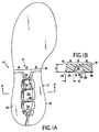
- outsole 10 has a lower surface part 12 having a central portion and peripheral portion generally shown by bracketed regions 14 and 16, respectively.
- Peripheral portion 16 is a region of the lower surface adjacent the whole of perimeter 18 of sole 10.
- Central portion 14 is the region surrounded by peripheral portion 16.
- strike plates 20 and 22 extending vertically downward from peripheral portion 16.
- Each strike plate has an outer wall 24, shown in the Figures as being outwardly inclined to the vertical, extending from perimeter 18, and an inner angled wall 26 extending generally from the junction of peripheral portion 16 and central portion 14.
- Angled walls 26 are formed at an obtuse angle to the surface of the bottom of the concavity. 12. This angle is generally between 95° and 135°.
- Each strike plate has a generally planar (or flat) surface 28 spaced from peripheral portion 16 and adapted to contact ground during use of the outsole.
- a planar surface may be provided with dimples or other fine indentations to provide more friction with the ground. In this invention, however, such dimples or ridges are included in the term "planar surface”.
- Strike plates 20 and 22 together define a central concavity 30 disposed above central portion 14 and between the strike plates. It extends to a plane 31 defined by surfaces 28. Angled walls 26 are adjacent central concavity 30. Strike plates 20 and 22 extend from peripheral portion 16, a distance D of at least 1.5 millimeters, preferably between 0.5 and 1.5 centimeters. In addition, the strike plates extend inwardly from perimeter 18, a distance E, preferably between 0.5 and 1.5 centimeters, most preferably at least one centimeter.
- membranes 32 are also provided in outsole 10 and a plurality of elastic membranes 32 connecting strike plates 20 and 22 and extending through central concavity 30.
- Membranes 32 are formed of material having a lesser stiffness than that of one of the strike plates to which they are connected.
- membranes 32 are formed of a thickness in at least one dimension, e.g., shown by arrow B, which is less than the transverse width C of one of strike plates 20 and 22 to which the membrane is connected.
- Central concavity 30 in outsole 10 is generally lengthwise oriented in the heel region of the outsole, and the pair of strike plates and membrane together form an A shape.
- FIGs. 9A-9D there is shown the effect of a force applied to an outsole.
- the outsole has a pair of outwardly angled lugs 130 which are caused to bend (as shown by arrows 132) when a force 134 is applied and the lugs are contacted with ground 136.
- Force 134 is moderately absorbed by bending of lugs 130.
- a force 140 is applied to an outsole of the present invention, e.g., to a pair of strike plates 142 (having a planar surface 146) connected together by a membrane 144, force 140 is absorbed by extension of membrane 144, as shown by arrows 150.
- the above described outsole may be formed from any standard footwear material.
- the membrane may be of any elastic material, for example, rubber (synthetic or natural) or polymer such as PVC, PU, Nylon®, Surlyn®, Hytrel® or metal.
- the angled walls of the strike plates may be of any material which is stiffer than such a membrane.
- the membrane and angled walls may be made of the same material so long as the membrane has at least one dimension which is thinner than a transverse section of a strike plate.
- the strike plates may be formed from a different material on their surfaces and their inner portions.
- the surface may be formed of any standard outsole material and the inner portion formed of foam. In this way the outsole may first be molded and then foam applied to its upper surface.
- the outsole may be manufactured by any standard procedure.
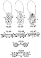
- outsole 40 is provided with pairs of strike plates 42, 44, and 46, each connected by one or more membranes 48, 50, and 52, respectively.
- This construction is similar to the outsole in Fig. 1, but has relatively large strike plates 20 and 22 separated into smaller strike plates.
- Such construction provides better outsole to surface contact in moist conditions, or when the ground contains many small particles, e.g., rotten fruit.
- FIGs. 3A, 3B, and 3C there are shown various patterns by which strike plates 50 can be connected by membranes 52. Connecting membranes of this invention must merely connect any two points or strike plates which are caused to move apart when a vertical or near vertical force is applied to the strike plates.
- Figs. 4A, 4B, and 4C show various membrane designs suitable in this invention.
- a membrane 54 connects strike plates 56 from the base of central portion 58 to a plane 60 defined by planar surfaces 61 of strike plates 56.
- a membrane 62 extends between two strike plates 64, from a plane 66 defined by a planar surface of strike plates 64, and extends through only a portion of central concavity 68.
- membrane 70 extends between two strike plates 72 from central portion 74 to a level plane within central cavity 76.
- a membrane 80 connecting a pair of cleats 82 for example cleats used on athletic shoes used for football or soccer.
- Cleats 82 are the equivalent of a strike plate discussed above.
- FIG. 6A strike plates 90 extend the length of an outsole, and connecting membranes 92 extend transversely between the strike plates.
- strike plates 94 are provided only in the heel region of the outsole, and membranes 96 are provided in a transverse direction between these strike plates.
- strike plates 98 also extend only in the heel region of an outsole but one such strike plate extends around the whole of the end of the heel. These strike plates are connected by membranes positioned at various angles to the longitudinal axis of the outsole.
- strike plates 102 and 104 are located partially in the heel region and partially in the toe region of the outsole, and are connected by generally longitudinally aligned membranes 106.
- FIG. 7 there is shown a transverse section of an outsole having a pair of strike plates 110 and 112 connected together by a membrane 114. Strike plates 110 and 112 are formed with outer edges 116 and 118 extending from a peripheral edge 120 of the outsole at a right angle to peripheral region 122. Such strike plate construction on an outsole permits easier attachment of an upper or midsole to the outsole.
- FIGs. 8A, and 8B there are shown examples of inwardly angled walls of a strike plate.
- an inwardly angled wall 124 is formed as a regular angled portion
- in Fig. 8B inwardly angled wall 126 is provided with a short vertical extension 128.
Landscapes
- Footwear And Its Accessory, Manufacturing Method And Apparatuses (AREA)
- Details Of Rigid Or Semi-Rigid Containers (AREA)
- Surgical Instruments (AREA)
Claims (16)
- Laufsohle für einen Fußbekleidungsartikel, wobei die Laufsohle einen mittleren Abschnitt (14) und einen umfangsseitigen Abschnitt (16) aufweist, und mit einer Vielzahl von elastischen, Stöße absorbierenden Aufprallplatten (20, 22), die sich ausgehend von dem umfangsseitigen Abschnitt (16) erstrecken und dort herum angeordnet sind, um eine zentrale Austiefung (30) in dem mittleren Abschnitt (14) zu bilden, wobei jede Aufprallplatte eine nach innen abgeschrägte Wand (26) nahe der zentralen Austiefung (30) aufweist, wobei sich die abgeschrägte Wand (26) in einem stumpfen Winkel zu dem mittleren Abschnitt (14) befindet, dadurch gekennzeichnet, daß sich eine elastische Membran (32) durch die zentrale Austiefung (30) erstreckt, um eine Vielzahl der Aufprallplatten zu verbinden, wobei die Membran (32) eine Steifigkeit aufweist, die geringer als die einer der Aufprallplatten (20, 22) ist, mit der sie verbunden ist.
- Laufsohle nach Anspruch 1, bei der die elastische Membran (62) von dem mittleren Abschnitt (14) getrennt ist.
- Laufsohle nach Anspruch 1, bei der sich die Membran (32) ausgehend von dem mittleren Abschnitt (14) erstreckt.
- Laufsohle nach Anspruch 1, 2 oder 3, bei der die zentrale Austiefung (30) in Längsrichtung entlang der Laufsohle ausgerichtet ist.
- Laufsohle nach einem der vorhergehenden Ansprüche, bei der ein Paar der Aufprallplatten (20, 22) und eine Verbindungsmembran (32) in der Form eines A vorliegen.
- Laufsohle nach einem der vorhergehenden Ansprüche, bei der die Aufprallplatten (20, 22) und die Verbindungsmembran (32) im Absatzbereich der Laufsohle angeordnet sind.
- Laufsohle nach einem der Ansprüche 1 bis 5, bei der sich die Aufprallplatten (90) und die Membran (92) in dem mittleren und seitlichen Bereich der Laufsohle befinden.
- Laufsohle nach einem der vorhergehenden Ansprüche, bei der sich die Membran (54) zu einer Kante der zentralen Austiefung (58) erstreckt, die von einer Ebene gebildet wird, die sich ausgehend von dem Abschnitt einer Vielzahl von den Aufprallplatten (56) aus erstreckt, der am weitesten weg von dem umfangsseitigen Abschnitt ist.
- Laufsohle nach einem der vorhergehenden Ansprüche, bei der zwei Aufprallplatten (20, 22) vorgesehen sind und mehr als eine Membran (32) die Aufprallplatten verbinden.
- Laufsohle nach einem der vorhergehenden Ansprüche, bei der die Membran (32) eine Dicke in zumindest einer Abmessung von weniger als die Querbreite einer der Aufprallplatten (20, 22) aufweist, mit der sie verbunden ist.
- Laufsohle nach einem der vorhergehenden Ansprüche, bei der die Aufprallplatten (20, 22) eine im allgemeinen flache Oberfläche (28) aufweisen, die von dem umfangsseitigen Abschnitt beabstandet ist und so ausgelegt ist, daß sie bewirken kann, daß die gesamte flache Oberfläche den Boden während der Verwendung der Laufsohle berührt.
- Laufsohle nach einem der vorhergehenden Ansprüche, bei der die Membran (32) so ausgelegt ist, daß sie durch Ausdehnung einen Teil einer vertikalen Kraft absorbiert, die an eine Aufprallplatte (20, 22) angelegt wird.
- Laufsohle nach einem der vorhergehenden Ansprüche, bei der sich die Aufprallplatten (20, 22) ausgehend von dem umfangsseitigen Abschnitt um mindestens 1,5 mm erstrecken.
- Laufsohle nach einem der vorhergehenden Ansprüche, bei der sich eine Aufprallplatte (20, 22) nach innen um mindestens 1 cm ausgehend von der Kante des umfangsseitigen Abschnitts (16) erstreckt.
- Laufsohle nach Anspruch 1, 2 oder 3, bei der die Aufprallplatte (20, 22) eine nach außen abgeschrägte äußere Wand (24) aufweist.
- Laufsohle nach Anspruch 15, bei der die nach außen abgeschrägte Wand (24) einen Winkel mit der Vertikalen von 0° bis einschließlich 15° bildet.
Applications Claiming Priority (3)
| Application Number | Priority Date | Filing Date | Title |
|---|---|---|---|
| US07/478,476 US5005299A (en) | 1990-02-12 | 1990-02-12 | Shock absorbing outsole for footwear |
| US478476 | 1990-02-12 | ||
| PCT/US1991/000943 WO1991011926A1 (en) | 1990-02-12 | 1991-02-11 | Shock absorbing outsole for footwear |
Publications (3)
| Publication Number | Publication Date |
|---|---|
| EP0515547A1 EP0515547A1 (de) | 1992-12-02 |
| EP0515547A4 EP0515547A4 (en) | 1993-01-07 |
| EP0515547B1 true EP0515547B1 (de) | 1994-09-14 |
Family
ID=23900108
Family Applications (1)
| Application Number | Title | Priority Date | Filing Date |
|---|---|---|---|
| EP91905211A Expired - Lifetime EP0515547B1 (de) | 1990-02-12 | 1991-02-11 | Stossabsorbierende aussensohle für schuhwerk |
Country Status (8)
| Country | Link |
|---|---|
| US (1) | US5005299A (de) |
| EP (1) | EP0515547B1 (de) |
| JP (1) | JPH0785721B2 (de) |
| AU (1) | AU7445191A (de) |
| CA (1) | CA2075483C (de) |
| DE (1) | DE69104030T2 (de) |
| ES (1) | ES2064093T3 (de) |
| WO (1) | WO1991011926A1 (de) |
Families Citing this family (55)
| Publication number | Priority date | Publication date | Assignee | Title |
|---|---|---|---|---|
| US5224280A (en) * | 1991-08-28 | 1993-07-06 | Pagoda Trading Company, Inc. | Support structure for footwear and footwear incorporating same |
| CA2051230C (en) * | 1991-09-12 | 1997-11-18 | Robert Burke | Power midsole cushioning and stability concept |
| US5440826A (en) * | 1992-04-08 | 1995-08-15 | Whatley; Ian H. | Shock absorbing outsole for footwear |
| US5325611A (en) * | 1992-10-19 | 1994-07-05 | Brown Group, Inc. | Comfort cradle system for footwear construction |
| USD348354S (en) | 1993-02-05 | 1994-07-05 | Nike, Inc. | Support element for a shoe sole |
| US5625964A (en) * | 1993-03-29 | 1997-05-06 | Nike, Inc. | Athletic shoe with rearfoot strike zone |
| US5425184A (en) * | 1993-03-29 | 1995-06-20 | Nike, Inc. | Athletic shoe with rearfoot strike zone |
| US5918384A (en) | 1993-08-17 | 1999-07-06 | Akeva L.L.C. | Athletic shoe with improved sole |
| WO1995020333A1 (en) * | 1994-01-27 | 1995-08-03 | Miner Enterprises, Inc. | Elastomer midsole shoe structure |
| US5595004A (en) * | 1994-03-30 | 1997-01-21 | Nike, Inc. | Shoe sole including a peripherally-disposed cushioning bladder |
| US5678327A (en) * | 1994-07-21 | 1997-10-21 | Halberstadt; Johan P. | Shoe with gait-adapting cushioning mechanism |
| US7540099B2 (en) * | 1994-08-17 | 2009-06-02 | Akeva L.L.C. | Heel support for athletic shoe |
| US5628128A (en) * | 1994-11-01 | 1997-05-13 | American Sporting Goods Corp. | Sole construction for footwear |
| US5625963A (en) * | 1994-11-01 | 1997-05-06 | American Sporting Goods Corp. | Sole construction for footwear |
| US5647145A (en) * | 1995-06-05 | 1997-07-15 | Russell; Brian | Sculptured athletic footwear sole construction |
| US5806210A (en) | 1995-10-12 | 1998-09-15 | Akeva L.L.C. | Athletic shoe with improved heel structure |
| US5678329A (en) * | 1996-04-03 | 1997-10-21 | Wilson Sporting Goods Co. | Athletic shoe with midsole side support |
| US5680714A (en) * | 1996-07-08 | 1997-10-28 | Lopez; Randy Gerald | Trampoline effect athletic shoe having elastic sole return strips |
| US5937544A (en) * | 1997-07-30 | 1999-08-17 | Britek Footwear Development, Llc | Athletic footwear sole construction enabling enhanced energy storage, retrieval and guidance |
| US6330757B1 (en) | 1998-08-18 | 2001-12-18 | Britek Footwear Development, Llc | Footwear with energy storing sole construction |
| US6327795B1 (en) * | 1997-07-30 | 2001-12-11 | Britek Footwear Development, Llc | Sole construction for energy storage and rebound |
| WO2002078480A2 (en) * | 2000-12-01 | 2002-10-10 | Britek Footwear Development, Llc | Sole construction for energy storage and rebound |
| US7178267B2 (en) * | 2003-12-12 | 2007-02-20 | Polyworks, Inc. | Method for forming footwear structures using thermoforming |
| US7100310B2 (en) * | 2003-12-23 | 2006-09-05 | Nike, Inc. | Article of footwear having a fluid-filled bladder with a reinforcing structure |
| US7086179B2 (en) * | 2003-12-23 | 2006-08-08 | Nike, Inc. | Article of footwear having a fluid-filled bladder with a reinforcing structure |
| US7562469B2 (en) | 2003-12-23 | 2009-07-21 | Nike, Inc. | Footwear with fluid-filled bladder and a reinforcing structure |
| US7141131B2 (en) * | 2003-12-23 | 2006-11-28 | Nike, Inc. | Method of making article of footwear having a fluid-filled bladder with a reinforcing structure |
| US7556846B2 (en) * | 2003-12-23 | 2009-07-07 | Nike, Inc. | Fluid-filled bladder with a reinforcing structure |
| US7086180B2 (en) * | 2003-12-23 | 2006-08-08 | Nike, Inc. | Article of footwear having a fluid-filled bladder with a reinforcing structure |
| US7152343B2 (en) * | 2004-06-25 | 2006-12-26 | Cronus, Inc. | Footwear system |
| US8082684B2 (en) * | 2004-08-18 | 2011-12-27 | Fox Head, Inc. | Footwear with bridged decoupling |
| US7571556B2 (en) * | 2004-12-28 | 2009-08-11 | Saucony, Inc. | Heel grid system |
| JP2008532618A (ja) * | 2005-03-10 | 2008-08-21 | ニュー バランス アスレティック シュー,インコーポレーテッド | 履物用の機械的緩衝システム |
| USD521715S1 (en) | 2005-09-22 | 2006-05-30 | Nike, Inc. | Portion of a shoe sole |
| US7533477B2 (en) * | 2005-10-03 | 2009-05-19 | Nike, Inc. | Article of footwear with a sole structure having fluid-filled support elements |
| CN101573058A (zh) | 2006-11-06 | 2009-11-04 | 牛顿跑步公司 | 用于能量存储和复原的鞋底结构 |
| WO2008083408A2 (en) * | 2007-01-02 | 2008-07-10 | Polyworks, Inc. | Cushioning materials, methods of making, and articles formed thereby |
| US8051583B2 (en) * | 2007-09-06 | 2011-11-08 | Nike, Inc. | Article of footwear with improved stability and balance |
| US9003679B2 (en) | 2008-08-06 | 2015-04-14 | Nike, Inc. | Customization of inner sole board |
| US9750307B2 (en) | 2013-02-21 | 2017-09-05 | Nike, Inc. | Article of footwear having a sole structure including a fluid-filled chamber and an outsole, the sole structure, and methods for manufacturing |
| US9894959B2 (en) | 2009-12-03 | 2018-02-20 | Nike, Inc. | Tethered fluid-filled chamber with multiple tether configurations |
| US9521877B2 (en) | 2013-02-21 | 2016-12-20 | Nike, Inc. | Article of footwear with outsole bonded to cushioning component and method of manufacturing an article of footwear |
| US9420848B2 (en) | 2013-02-21 | 2016-08-23 | Nike, Inc. | Article of footwear incorporating a chamber system and methods for manufacturing the chamber system |
| US9987814B2 (en) | 2013-02-21 | 2018-06-05 | Nike, Inc. | Method of co-molding |
| US9167867B2 (en) * | 2010-05-13 | 2015-10-27 | Nike, Inc. | Article of footwear with multi-part sole assembly |
| US8584377B2 (en) | 2010-09-14 | 2013-11-19 | Nike, Inc. | Article of footwear with elongated shock absorbing heel system |
| US9981437B2 (en) | 2013-02-21 | 2018-05-29 | Nike, Inc. | Article of footwear with first and second outsole components and method of manufacturing an article of footwear |
| US10058144B2 (en) * | 2014-08-06 | 2018-08-28 | Nike, Inc. | Article of footwear with midsole with arcuate underside cavity |
| DE212017000085U1 (de) | 2016-03-15 | 2018-10-26 | Nike Innovate C.V. | Fussbekleidungsartikel |
| US10966482B2 (en) * | 2018-10-12 | 2021-04-06 | Deckers Outdoor Corporation | Footwear with stabilizing sole |
| US11730228B2 (en) | 2018-10-12 | 2023-08-22 | Deckers Outdoor Corporation | Footwear with stabilizing sole |
| US11723428B2 (en) | 2018-10-12 | 2023-08-15 | Deckers Outdoor Corporation | Footwear with stabilizing sole |
| US11388949B2 (en) * | 2018-12-03 | 2022-07-19 | Cole Haan Llc | Shoe having a concave outsole |
| US12171300B2 (en) * | 2019-03-28 | 2024-12-24 | Nike, Inc. | Sole structure of an article of footwear |
| US12369685B1 (en) | 2024-06-12 | 2025-07-29 | 1158990 B.C. Ltd. | Shoe midsole with delayed energy return and lateral shear stability |
Citations (1)
| Publication number | Priority date | Publication date | Assignee | Title |
|---|---|---|---|---|
| US8911047B2 (en) * | 2010-12-14 | 2014-12-16 | Seiko Epson Corporation | Fluid ejecting apparatus and fluid ejecting method |
Family Cites Families (22)
| Publication number | Priority date | Publication date | Assignee | Title |
|---|---|---|---|---|
| US2887794A (en) * | 1955-02-07 | 1959-05-26 | Masera Giovanni | Shoe made of thermo-plastic or thermosetting material or the like |
| US2885797A (en) * | 1957-08-16 | 1959-05-12 | Edward W Chrencik | Shoe construction with resilient heel and arch support |
| US3100354A (en) * | 1962-12-13 | 1963-08-13 | Lombard Herman | Resilient shoe sole |
| DE2216872C3 (de) * | 1972-04-07 | 1982-04-08 | Adidas Sportschuhfabriken Adi Dassler Kg, 8522 Herzogenaurach | Laufsohle aus biegeelastischem Kunststoff für Sportschuhe |
| US3793750A (en) * | 1972-08-30 | 1974-02-26 | Brs Inc | Athletic shoe for artificial turf |
| US3818618A (en) * | 1972-09-19 | 1974-06-25 | Westinghouse Air Brake Co | Linkage for ground positioning of an earth scraper elevator |
| US4043058A (en) * | 1976-05-21 | 1977-08-23 | Brs, Inc. | Athletic training shoe having foam core and apertured sole layers |
| US4096649A (en) * | 1976-12-03 | 1978-06-27 | Saurwein Albert C | Athletic shoe sole |
| US4085527A (en) * | 1977-02-01 | 1978-04-25 | Riggs Donnie E | Athletic shoe |
| US4128950A (en) * | 1977-02-07 | 1978-12-12 | Brs, Inc. | Multilayered sole athletic shoe with improved foam mid-sole |
| US4094081A (en) * | 1977-04-11 | 1978-06-13 | Joseph Reiner | Beach sandal |
| US4741114A (en) * | 1977-11-21 | 1988-05-03 | Avia Group International, Inc. | Shoe sole construction |
| DE2753205C3 (de) * | 1977-11-29 | 1985-12-12 | Michael W. Dipl.-Kfm. 5100 Aachen Schmohl | Durchgehende Laufsohle für Sportschuhe |
| ZA784637B (en) * | 1978-08-15 | 1979-09-26 | J Halberstadt | Footware |
| FR2434587A1 (fr) * | 1978-09-04 | 1980-03-28 | Adidas Chaussures | Semelle de chaussures destinees aux sports en salle |
| US4297796A (en) * | 1979-07-23 | 1981-11-03 | Stirtz Ronald H | Shoe with three-dimensionally transmitting shock-absorbing mechanism |
| US4271606A (en) * | 1979-10-15 | 1981-06-09 | Robert C. Bogert | Shoes with studded soles |
| US4546556A (en) * | 1981-04-03 | 1985-10-15 | Pensa, Inc. | Basketball shoe sole |
| IT8430738V0 (it) * | 1984-05-18 | 1984-05-18 | Danieli Calzaturificio Spa | Struttura di suola a cedevolezza diversificabile. |
| DE3527938A1 (de) * | 1985-08-03 | 1987-02-12 | Paul Ganter | Schuh- oder laufsohle |
| US4730402A (en) * | 1986-04-04 | 1988-03-15 | New Balance Athletic Shoe, Inc. | Construction of sole unit for footwear |
| DE3906466A1 (de) * | 1988-05-13 | 1989-11-23 | Polus Michael | Daempfungsvorrichtung fuer stossbelastungen |
-
1990
- 1990-02-12 US US07/478,476 patent/US5005299A/en not_active Expired - Lifetime
-
1991
- 1991-02-11 DE DE69104030T patent/DE69104030T2/de not_active Expired - Fee Related
- 1991-02-11 EP EP91905211A patent/EP0515547B1/de not_active Expired - Lifetime
- 1991-02-11 ES ES91905211T patent/ES2064093T3/es not_active Expired - Lifetime
- 1991-02-11 AU AU74451/91A patent/AU7445191A/en not_active Abandoned
- 1991-02-11 CA CA002075483A patent/CA2075483C/en not_active Expired - Fee Related
- 1991-02-11 JP JP3505090A patent/JPH0785721B2/ja not_active Expired - Lifetime
- 1991-02-11 WO PCT/US1991/000943 patent/WO1991011926A1/en not_active Ceased
Patent Citations (1)
| Publication number | Priority date | Publication date | Assignee | Title |
|---|---|---|---|---|
| US8911047B2 (en) * | 2010-12-14 | 2014-12-16 | Seiko Epson Corporation | Fluid ejecting apparatus and fluid ejecting method |
Also Published As
| Publication number | Publication date |
|---|---|
| JPH0785721B2 (ja) | 1995-09-20 |
| DE69104030D1 (de) | 1994-10-20 |
| DE69104030T2 (de) | 1995-01-26 |
| WO1991011926A1 (en) | 1991-08-22 |
| EP0515547A4 (en) | 1993-01-07 |
| EP0515547A1 (de) | 1992-12-02 |
| JPH05503455A (ja) | 1993-06-10 |
| CA2075483C (en) | 1996-07-30 |
| US5005299A (en) | 1991-04-09 |
| ES2064093T3 (es) | 1995-01-16 |
| AU7445191A (en) | 1991-09-03 |
Similar Documents
| Publication | Publication Date | Title |
|---|---|---|
| EP0515547B1 (de) | Stossabsorbierende aussensohle für schuhwerk | |
| US5440826A (en) | Shock absorbing outsole for footwear | |
| US5060401A (en) | Footwear cushinoning spring | |
| US4667425A (en) | Baseball shoe with improved outsole | |
| US6289608B1 (en) | Athletic shoe midsole design and construction | |
| EP0076313B1 (de) | Sohle für basketballschuhe | |
| US4624062A (en) | Sole with cushioning and braking spiroidal contact surfaces | |
| EP0963711B1 (de) | Gestaltung und Aufbau einer Mittelsohle für Athletikschuh | |
| CA1338231C (en) | Athletic shoe with energy storing spring | |
| US6857205B1 (en) | Article of footwear having a sole structure with a split plate | |
| US7549236B2 (en) | Footwear with independent suspension and protection | |
| US5983529A (en) | Footwear shock absorbing system | |
| EP0966895B1 (de) | Gestaltung und Aufbau einer Mittelsohle für Athletikschuh | |
| US6711834B1 (en) | Sole structure of athletic shoe | |
| RU2385140C2 (ru) | Подошва с тангенциальной деформируемостью | |
| US7062865B1 (en) | Orthotic | |
| US20110072684A1 (en) | Support structures in footwear | |
| US20020004999A1 (en) | Sole for a trail running shoe | |
| EP0058690A4 (de) | Sportschuh mit fersenstabilisierung. | |
| US5218773A (en) | Torsionally stabilized athletic shoe | |
| EP3267826B1 (de) | Auxetische sohlen mit entsprechenden innen- oder aussenauskleidungen | |
| JPH0420606B2 (de) | ||
| CN223682070U (zh) | 一种支撑性能稳定的运动鞋 | |
| JPH0617504U (ja) | 運動靴底 | |
| JPH0420607B2 (de) |
Legal Events
| Date | Code | Title | Description |
|---|---|---|---|
| PUAI | Public reference made under article 153(3) epc to a published international application that has entered the european phase |
Free format text: ORIGINAL CODE: 0009012 |
|
| 17P | Request for examination filed |
Effective date: 19920730 |
|
| AK | Designated contracting states |
Kind code of ref document: A1 Designated state(s): DE DK ES FR GB IT |
|
| A4 | Supplementary search report drawn up and despatched |
Effective date: 19921116 |
|
| AK | Designated contracting states |
Kind code of ref document: A4 Designated state(s): DE DK ES FR GB IT |
|
| 17Q | First examination report despatched |
Effective date: 19930715 |
|
| RAP1 | Party data changed (applicant data changed or rights of an application transferred) |
Owner name: WHATLEY, IAN H. |
|
| GRAA | (expected) grant |
Free format text: ORIGINAL CODE: 0009210 |
|
| AK | Designated contracting states |
Kind code of ref document: B1 Designated state(s): DE DK ES FR GB IT |
|
| PG25 | Lapsed in a contracting state [announced via postgrant information from national office to epo] |
Ref country code: DK Effective date: 19940914 |
|
| REF | Corresponds to: |
Ref document number: 69104030 Country of ref document: DE Date of ref document: 19941020 |
|
| ITF | It: translation for a ep patent filed | ||
| ET | Fr: translation filed | ||
| REG | Reference to a national code |
Ref country code: ES Ref legal event code: FG2A Ref document number: 2064093 Country of ref document: ES Kind code of ref document: T3 |
|
| PLBE | No opposition filed within time limit |
Free format text: ORIGINAL CODE: 0009261 |
|
| STAA | Information on the status of an ep patent application or granted ep patent |
Free format text: STATUS: NO OPPOSITION FILED WITHIN TIME LIMIT |
|
| 26N | No opposition filed | ||
| PGFP | Annual fee paid to national office [announced via postgrant information from national office to epo] |
Ref country code: GB Payment date: 19991224 Year of fee payment: 10 |
|
| PGFP | Annual fee paid to national office [announced via postgrant information from national office to epo] |
Ref country code: DE Payment date: 19991229 Year of fee payment: 10 |
|
| PGFP | Annual fee paid to national office [announced via postgrant information from national office to epo] |
Ref country code: FR Payment date: 20000207 Year of fee payment: 10 |
|
| PGFP | Annual fee paid to national office [announced via postgrant information from national office to epo] |
Ref country code: ES Payment date: 20000216 Year of fee payment: 10 |
|
| PG25 | Lapsed in a contracting state [announced via postgrant information from national office to epo] |
Ref country code: GB Free format text: LAPSE BECAUSE OF NON-PAYMENT OF DUE FEES Effective date: 20010211 |
|
| PG25 | Lapsed in a contracting state [announced via postgrant information from national office to epo] |
Ref country code: ES Free format text: LAPSE BECAUSE OF NON-PAYMENT OF DUE FEES Effective date: 20010212 |
|
| GBPC | Gb: european patent ceased through non-payment of renewal fee |
Effective date: 20010211 |
|
| PG25 | Lapsed in a contracting state [announced via postgrant information from national office to epo] |
Ref country code: FR Free format text: LAPSE BECAUSE OF NON-PAYMENT OF DUE FEES Effective date: 20011031 |
|
| REG | Reference to a national code |
Ref country code: FR Ref legal event code: ST |
|
| PG25 | Lapsed in a contracting state [announced via postgrant information from national office to epo] |
Ref country code: DE Free format text: LAPSE BECAUSE OF NON-PAYMENT OF DUE FEES Effective date: 20011201 |
|
| REG | Reference to a national code |
Ref country code: ES Ref legal event code: FD2A Effective date: 20021016 |
|
| PG25 | Lapsed in a contracting state [announced via postgrant information from national office to epo] |
Ref country code: IT Free format text: LAPSE BECAUSE OF NON-PAYMENT OF DUE FEES;WARNING: LAPSES OF ITALIAN PATENTS WITH EFFECTIVE DATE BEFORE 2007 MAY HAVE OCCURRED AT ANY TIME BEFORE 2007. THE CORRECT EFFECTIVE DATE MAY BE DIFFERENT FROM THE ONE RECORDED. Effective date: 20050211 |