EP0515628B1 - Dispositif et procede pour la sterilisation d'eau - Google Patents
Dispositif et procede pour la sterilisation d'eau Download PDFInfo
- Publication number
- EP0515628B1 EP0515628B1 EP92901093A EP92901093A EP0515628B1 EP 0515628 B1 EP0515628 B1 EP 0515628B1 EP 92901093 A EP92901093 A EP 92901093A EP 92901093 A EP92901093 A EP 92901093A EP 0515628 B1 EP0515628 B1 EP 0515628B1
- Authority
- EP
- European Patent Office
- Prior art keywords
- anode
- cathode
- cathodes
- anodes
- reactor
- Prior art date
- Legal status (The legal status is an assumption and is not a legal conclusion. Google has not performed a legal analysis and makes no representation as to the accuracy of the status listed.)
- Expired - Lifetime
Links
Images


Classifications
-
- C—CHEMISTRY; METALLURGY
- C02—TREATMENT OF WATER, WASTE WATER, SEWAGE, OR SLUDGE
- C02F—TREATMENT OF WATER, WASTE WATER, SEWAGE, OR SLUDGE
- C02F1/00—Treatment of water, waste water, or sewage
- C02F1/46—Treatment of water, waste water, or sewage by electrochemical methods
- C02F1/461—Treatment of water, waste water, or sewage by electrochemical methods by electrolysis
- C02F1/467—Treatment of water, waste water, or sewage by electrochemical methods by electrolysis by electrochemical disinfection; by electrooxydation or by electroreduction
- C02F1/4672—Treatment of water, waste water, or sewage by electrochemical methods by electrolysis by electrochemical disinfection; by electrooxydation or by electroreduction by electrooxydation
- C02F1/4674—Treatment of water, waste water, or sewage by electrochemical methods by electrolysis by electrochemical disinfection; by electrooxydation or by electroreduction by electrooxydation with halogen or compound of halogens, e.g. chlorine, bromine
-
- C—CHEMISTRY; METALLURGY
- C02—TREATMENT OF WATER, WASTE WATER, SEWAGE, OR SLUDGE
- C02F—TREATMENT OF WATER, WASTE WATER, SEWAGE, OR SLUDGE
- C02F1/00—Treatment of water, waste water, or sewage
- C02F1/46—Treatment of water, waste water, or sewage by electrochemical methods
- C02F1/461—Treatment of water, waste water, or sewage by electrochemical methods by electrolysis
- C02F1/46104—Devices therefor; Their operating or servicing
-
- C—CHEMISTRY; METALLURGY
- C02—TREATMENT OF WATER, WASTE WATER, SEWAGE, OR SLUDGE
- C02F—TREATMENT OF WATER, WASTE WATER, SEWAGE, OR SLUDGE
- C02F1/00—Treatment of water, waste water, or sewage
- C02F1/46—Treatment of water, waste water, or sewage by electrochemical methods
- C02F1/461—Treatment of water, waste water, or sewage by electrochemical methods by electrolysis
- C02F1/46104—Devices therefor; Their operating or servicing
- C02F1/46109—Electrodes
-
- C—CHEMISTRY; METALLURGY
- C02—TREATMENT OF WATER, WASTE WATER, SEWAGE, OR SLUDGE
- C02F—TREATMENT OF WATER, WASTE WATER, SEWAGE, OR SLUDGE
- C02F1/00—Treatment of water, waste water, or sewage
- C02F1/46—Treatment of water, waste water, or sewage by electrochemical methods
- C02F1/461—Treatment of water, waste water, or sewage by electrochemical methods by electrolysis
- C02F1/46104—Devices therefor; Their operating or servicing
- C02F1/46109—Electrodes
- C02F2001/46133—Electrodes characterised by the material
-
- C—CHEMISTRY; METALLURGY
- C02—TREATMENT OF WATER, WASTE WATER, SEWAGE, OR SLUDGE
- C02F—TREATMENT OF WATER, WASTE WATER, SEWAGE, OR SLUDGE
- C02F1/00—Treatment of water, waste water, or sewage
- C02F1/46—Treatment of water, waste water, or sewage by electrochemical methods
- C02F1/461—Treatment of water, waste water, or sewage by electrochemical methods by electrolysis
- C02F1/46104—Devices therefor; Their operating or servicing
- C02F1/46109—Electrodes
- C02F2001/46133—Electrodes characterised by the material
- C02F2001/46138—Electrodes comprising a substrate and a coating
- C02F2001/46142—Catalytic coating
-
- C—CHEMISTRY; METALLURGY
- C02—TREATMENT OF WATER, WASTE WATER, SEWAGE, OR SLUDGE
- C02F—TREATMENT OF WATER, WASTE WATER, SEWAGE, OR SLUDGE
- C02F1/00—Treatment of water, waste water, or sewage
- C02F1/46—Treatment of water, waste water, or sewage by electrochemical methods
- C02F1/461—Treatment of water, waste water, or sewage by electrochemical methods by electrolysis
- C02F1/46104—Devices therefor; Their operating or servicing
- C02F1/46109—Electrodes
- C02F2001/46152—Electrodes characterised by the shape or form
-
- C—CHEMISTRY; METALLURGY
- C02—TREATMENT OF WATER, WASTE WATER, SEWAGE, OR SLUDGE
- C02F—TREATMENT OF WATER, WASTE WATER, SEWAGE, OR SLUDGE
- C02F2201/00—Apparatus for treatment of water, waste water or sewage
- C02F2201/46—Apparatus for electrochemical processes
- C02F2201/461—Electrolysis apparatus
- C02F2201/46105—Details relating to the electrolytic devices
- C02F2201/4612—Controlling or monitoring
- C02F2201/46125—Electrical variables
-
- C—CHEMISTRY; METALLURGY
- C02—TREATMENT OF WATER, WASTE WATER, SEWAGE, OR SLUDGE
- C02F—TREATMENT OF WATER, WASTE WATER, SEWAGE, OR SLUDGE
- C02F2209/00—Controlling or monitoring parameters in water treatment
-
- C—CHEMISTRY; METALLURGY
- C02—TREATMENT OF WATER, WASTE WATER, SEWAGE, OR SLUDGE
- C02F—TREATMENT OF WATER, WASTE WATER, SEWAGE, OR SLUDGE
- C02F2209/00—Controlling or monitoring parameters in water treatment
- C02F2209/003—Downstream control, i.e. outlet monitoring, e.g. to check the treating agents, such as halogens or ozone, leaving the process
-
- C—CHEMISTRY; METALLURGY
- C02—TREATMENT OF WATER, WASTE WATER, SEWAGE, OR SLUDGE
- C02F—TREATMENT OF WATER, WASTE WATER, SEWAGE, OR SLUDGE
- C02F2209/00—Controlling or monitoring parameters in water treatment
- C02F2209/29—Chlorine compounds
-
- C—CHEMISTRY; METALLURGY
- C02—TREATMENT OF WATER, WASTE WATER, SEWAGE, OR SLUDGE
- C02F—TREATMENT OF WATER, WASTE WATER, SEWAGE, OR SLUDGE
- C02F2301/00—General aspects of water treatment
- C02F2301/02—Fluid flow conditions
- C02F2301/022—Laminar
-
- C—CHEMISTRY; METALLURGY
- C02—TREATMENT OF WATER, WASTE WATER, SEWAGE, OR SLUDGE
- C02F—TREATMENT OF WATER, WASTE WATER, SEWAGE, OR SLUDGE
- C02F2301/00—General aspects of water treatment
- C02F2301/08—Multistage treatments, e.g. repetition of the same process step under different conditions
-
- C—CHEMISTRY; METALLURGY
- C02—TREATMENT OF WATER, WASTE WATER, SEWAGE, OR SLUDGE
- C02F—TREATMENT OF WATER, WASTE WATER, SEWAGE, OR SLUDGE
- C02F2303/00—Specific treatment goals
- C02F2303/04—Disinfection
Definitions
- the invention relates to a device for disinfecting water by means of anodic oxidation with a water-flowable reactor having at least one anode and one cathode each, and an electrical power supply device connected to the anode and the cathode, with a gap between facing surfaces of the anode and cathode is provided with a constant gap width, wherein the anode consists of a valve metal core with a homogeneous electrocatalytically active coating, which is composed predominantly of a compound of titanium and at least one platinum metal.
- Such a device is known from US-A-4,202,738.
- a plurality of bipolar electrode plates are arranged, through which salted water flows.
- the part of the object relating to the device is achieved according to the characterizing part of patent claim 1 in that several anodes and several cathodes are arranged in an electrode module for a reactor and that a reactor has a plurality of electrode modules, that the electrode modules are connected to one another as an electrical series circuit and that both the anodes and the cathodes of each electrode module are connected to each other in an electrically conductive manner in parallel.
- the modular structure of the device also increases the cost-effectiveness of the device during manufacture and maintenance. It also enables a plurality of electrode modules to be connected to one another as an electrical series circuit. In this way it is achieved that, while maintaining the predetermined voltage prevailing between the anode and cathode, a considerable increase in the active reactor volume and the anode area is possible without increasing the total electrical current flowing through the reactor, since due to the series connection of the modules the necessary electrical power increase is achieved by increasing the total voltage applied to the reactor.
- a preferred further development of the device features a particularly suitable anode structure, the core of the anode consisting of valve metal, such as titanium, niobium or tantalum, due to the property of a valve metal to form a protective, stable oxide layer in the electrolyte, ensures that in areas in which the coating of the anode core has gaps, none Corrosion of the anode core occurs.
- the effectiveness of such an anode is further improved by providing a plurality of pairs of layers which are applied alternately to one another.
- a preferred valve metal for the anode core is titanium.
- the particularly smooth surface of the anode according to claim 5 increases the long-term constancy of the anode activity, since the entire active surface of the anode is not blocked by adsorbate layers due to the low roughness.
- Preferred configurations for ensuring a desired laminar flow are, according to claim 6, the parallel arrangement of anode and cathode, anode and cathode preferably being formed by plane-parallel plates, and, according to claim 8, the concentric arrangement of tubular anodes and tubular cathodes.
- the contacting of the electrodes according to claims 9, 10 and 11 largely prevents resistance polarization due to the high surface pressure between the interfaces of electrodes and spacer elements, so that electrochemical corrosion at the interfaces is almost avoided.
- This contacting is particularly safe and effective under water and can be released again at any time.
- a measuring device for determining the chlorine equivalents of the oxidants in the water and a control unit further processing this measuring signal for controlling the Power supply device provided, so a particularly effective automatic operation of the device can take place.
- a device is suitable for carrying out the method for disinfecting water by means of anodic oxidation according to claim 15, wherein by determining the concentration of the chlorine equivalents of the oxidants and comparing this measured concentration with a target value, namely the concentration which is used to kill the germs is necessary, the total electrical current density can be changed.
- the laminar flow between the facing surfaces of the anode and cathode ensures that even with only a low concentration of dissolved chloride; Ions in water are transported evenly to the anode boundary layer by means of electrostatic migration in the homogeneous potential field, without being hindered in their migration movement by turbulent flow vectors.
- the choice of anode material according to the invention ensures that the undesired generation of molecular oxygen - and thus the undesired formation of gas bubbles on the electrode surfaces compared to the production of chlorine, chlorine-oxygen acids, their salts and other oxidants, which can be determined as chlorine equivalents (such as all oxidants detectable with DPD (diethyl-p-phenylenediamine), predominantly HOCl and OCl-) are reduced.
- chlorine, chlorine-oxygen acids, their salts and other oxidants which can be determined as chlorine equivalents (such as all oxidants detectable with DPD (diethyl-p-phenylenediamine), predominantly HOCl and OCl-) are reduced.
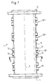
- a reactor 1 of a device for sterilizing water which has a tubular housing 10, at the axial ends of an inlet flange 11 and an outlet flange 12 are arranged.
- the housing 10 has four consecutive substantially identical housing sections 10 ', 10 ", 10"', 10 "" over its axial extent. Each of these housing sections is provided at diametrically opposite locations with a first 13 and a second 13 'contact bushing for the anode connection and a first 14 and a second (14') contact bushing for the cathode connection.
- the contact bushings 13, 13 ', 14, 14' are designed as radially extending tube sections which penetrate the wall of the housing 10 and are connected in a sealing and pressure-tight manner on their outer circumference to the wall of the housing 10.
- the first contact bushings 13, 14 and the second contact bushings 13 ', 14' are each arranged side by side in the direction of the axis X of the tubular housing 10.
- a housing 10 Since each housing section is provided with contact bushings 13, 13 ', 14, 14', a housing 10 has a plurality of diametrically opposite first and second contact bushing pairs corresponding to the number of housing sections, as can be seen in FIG. 1.
- Fig. 2 shows a cross section through a reactor 1 along the line II - II in Fig. 1.
- the tubular cross section of the housing 10 with the two radially opposite first and second contact bushings 14, 14 'for the cathode connection can be clearly seen.
- a square frame 20 is used, which serves to hold the electrodes 3, 4 and preferably consists of food-safe PVC.
- the corners of the frame 20 are chamfered or rounded on the outer sides and the frame 20 is inserted into the housing 10 with a precise fit such that the chamfered or rounded corners abut the inside of the tubular housing 10.
- the upper edge and the lower edge of the frame run parallel to the axis 14 '' common to the contact bushings 14, 14 '.
- the frame 20 consists of two side frame walls 23, 23 ', each of the first and the second contact bushing for the anode connection and the cathode connection 13, 14; 13 ', 14' are located adjacent.
- the upper and lower walls of the frame 20 are formed by an upper comb plate 21 and a lower comb plate 21 '.
- the comb plates 21, 21 ' are provided on their surface facing the inside of the frame with grooves 24 arranged next to one another and running parallel to the axis X of the housing 10.
- a web 22 projecting into the interior of the frame is provided between the grooves 24.
- the grooves 24 serve to guide plate-shaped electrodes 3, 4 inserted into the frame 20, which extend parallel to the side walls 23, 23 'of the frame 20 and whose plate size is preferably approximately 200 mm ⁇ 100 mm. Although only 3 electrodes are shown by way of example in FIG. 2, each pair of grooves 24, 24 'serves to guide an electrode, with cathode 4 and anode 3 alternating and each defining a gap 25 between them which defines the width of the associated web 22 or 22 'and is preferably approximately 1.3 mm, the respective thickness of the anode and cathode being approximately 1 mm.
- the number of cathodes is one more than that of the anodes, so that a cathode rests on each side wall 23, 23 'without a gap being formed between this outermost cathode and the associated side wall 23, 23'.
- the space 26 between the outside of the frame 20 and the inside of the tubular housing 10 is sealed off from the interior of the frame and filled or foamed, for example.
- the seal with respect to the interior of the frame 20 can be made, for example, by circular segment-shaped covers fastened in the area of the inlet flange 11 on the end faces of the frame walls, which covers only the preferably square inner surface of the frame 20 as a passage cross section for the water flowing through the reactor.
- Each housing section 10 ′, 10 ′′, 10 ′′ ′′, 10 ′′ ′′ has an electrode module (2 ′, 2 ′, 2 ′′, 2 ′′) configured as described above and arranged in a frame 20.
- FIG. 4 shows the alternating arrangement of anodes 3 and cathodes 4 with the gaps 25 in between.
- Each anode 3 and each cathode 4 has two spaced-apart openings of different diameters.
- the smaller opening 33 or 43 is designed for the loose passage of a tie rod 34 for the anode or a tie rod 44 for the cathode.
- the larger opening 45 of the cathode 4 permits the passage of the tie rod 34 of the anode, a radial distance being provided between the tie rod 34 and the opening edge of the opening 45.
- the larger opening 35 of the anode 3 allows the passage of the tie rod 44 of the cathode 4 while maintaining a radial distance.
- the respective tie rod 34 or 44 can consist of electrically conductive or non-conductive material.
- FIG. 5 shows the section labeled V in FIG. 4.
- the tie rod 44 penetrates the smaller openings 43 ', 43' 'of the successive cathodes 4', 4 '', the distance between the respective openings 43 ', 43' 'and the outer circumference of the tie rod 44 being such that there is axial movement of the tie rod 44 is possible.
- a conductive spacer ring 46 made of a valve metal, preferably titanium, which rests with its end faces against the mutually facing surfaces of the successive cathodes 4', 4 ''.
- the inner diameter of the spacer ring 46 corresponds essentially to the bores 43 ', 43' ', so that the spacer ring 46 does not hinder an axial movement of the tie rod 44 either.
- an insulating intermediate ring 47 Arranged radially outside of the conductive spacer ring 46 is an insulating intermediate ring 47 which, with its inner circumference, surrounds the outer circumference of the spacer ring 46 and which is somewhat shorter in the axial direction than a conductive spacer ring or is elastic and with its end faces on the mutually facing surfaces of the successive cathodes 4, 4 'is applied.
- the outer circumference of the insulating intermediate ring 47 lies against the inner circumference of the larger opening 35 of the anode 3 'located between the cathodes 4', 4 ''.
- the tie rod 44 on the cathode side is provided at its ends with a threaded section 44 ′, 44 ′′ in each case.
- the anode-side tie rod 34 also has threaded sections 34 'and 34' 'at its ends.
- a contact pin 7 shown in more detail in FIG. 3 is screwed by means of an internal thread 70, which is provided in an axial bore 71 located at one end of the contact pin 7.
- the latter has an annular end face 72 which comes into contact with the outer surface of the outermost cathode 4 '''and presses it against the spacer ring 46' located on the other side of this cathode.
- the result is at the respective separation points between the tie rod end face 72, the cathode 4' '', the spacer ring 46 ', the cathode 4' ', the spacer ring 46, the cathode 4', etc. a very high surface pressure, which reduces the respective electrical contact resistance and thus allows high electrical currents to be conducted between the contact bolts and between the cathodes while minimizing resistance losses. In this way, resistance polarization is avoided at the contact surfaces and the associated corrosion is prevented.
- the anodes are electrically contacted with one another and with the associated contact pins (not shown) which are assigned to them.
- a contact bolt with its annular end face 72 first presses against the annular end face of a conductive spacer ring 36 then again on the adjacent anode 3 '' etc.
- the electrode module 2 shown in FIG. 4 is contacted with the external power supply or with the next module via the cathode-side contact bolts 7, 7 'and the anode-side contact bolts, not shown in FIG. 4.
- the contact bolts 7, 7 ' are sealingly led out of the housing 10 through the associated contact bushing 14 or 14' for the cathode.
- the anode-side contact bolts, not shown, are led out of the housing 10 through the contact bushings 13, 13 '.
- a contact pin 7 has two axially spaced circumferential grooves 73, 74, in each of which a sealing ring 75, 76 is inserted, each with the groove 73 and 74 and the inner circumference of the contact bushing 14, 14 '; 13, 13 'cooperates in a sealing manner.
- the contact pin 7 is provided with an axial pin 78 to form a contact surface 77, which is designed to receive a known cable lug.
- the axial pin 78 is followed by an axially directed threaded bolt 79 which is designed to screw on a suitable nut which presses the cable lug (not shown) of a connecting cable against the contact surface 77.
- FIG. 6 The structure of an anode is shown in FIG. 6.
- a first layer 31 of a suitable conductive material is applied to an anode core 30, which is preferably made of a valve metal such as titanium, to which in turn a second layer 32 of another suitable conductive material is applied.
- the second layer can in turn be followed by a first layer and this in turn by a second layer, etc.
- One of the two layers 31, 32 consists of a titanium mixed oxide and the other of the two layers is made of a platinum-iridium alloy. It does not matter which of the two layers is applied first to the anode core 30; however, it is essential that the layers 31, 32 alternate with one another.
- a coating can be dispensed with in order to improve the electrical conductivity between the anodes and the adjacent spacer rings, so that the spacer rings directly on core 30 of the anode consisting of the valve metal.
- the cathode is preferably made of a (rustproof) stainless steel, such as V2A steel.
- the object of the invention is aimed at the overvoltage of the oxygen deposition over the overvoltage of the chlorine deposition through a particularly smooth surface and through the selection of the successive anode layers described above as high as possible.
- Fig. 7 shows the potential behavior of the selected anode with the structure described above (shown in broken lines).
- the ordinate shows the anode potential in volts and the abscissa shows the current density in mA / cm 2 .
- the solid curve indicates the chlorine evolution and the dash-dotted line represents the oxygen evolution.
- the partial oxygen stron density i 02 is lower than the partial chlorine stron density i Cl2 . It is thereby achieved that on the one hand the development of oxygen is reduced to a desired minimum even at high current densities and, on the other hand, due to the high potential, oxygen compounds with a high oxidation potential (peroxo compounds and singlet oxygen) are predominantly formed in addition to OH radicals.
- FIG. 8 shows the structure of a controlled device for the disinfection of water with a reactor 1, through which the water flows in FIG. 8 from bottom to top in the direction of the arrows W, W '.
- the reactor consists of four electrode modules 2 ', 2 ", 2"",2""' arranged one behind the other in the flow direction.
- the cathode side of the first electrode module 2 ' is the negative output pole of a power supply device 5 connected via a minus supply line 67.
- the minus supply line 67 is branched, each branch being connected to one of the contact bolts 7, 7' shown in Fig. 4.
- the two anode-side contact bolts of the electrode module 2 are connected to the cathode-side contact bolts of the following electrode module 2 ′′ via bridge lines 68, 69.
- the electrode modules 2 ′′ and 2 ′′ ′′ and 2 ′′ ′′ and 2 ′′ ′′ are electrically connected to one another
- the anode-side contact bolts of the last electrode module 2 '''' are the two branches of a plus supply line 66, which is also branched out connected, which connects the anodes of the last electrode module 2 '''' to the positive connection pole of the power supply device 5.
- the measuring point of a measuring device 60 is arranged, by means of which the oxidants contained in the water, which can be determined as chlorine equivalents, can be measured.
- the measuring device 60 is connected via a measuring line 63 to a computer unit 62, via which measurement data are supplied from the measuring device 60 to the computer unit 62.
- the computer unit 62 determines from the measurement data supplied to it the concentration of the oxidants contained in the water of the outlet channel, which can be determined as chlorine equivalents. From this concentration, the computer unit determines the partial chloride current density using data supplied by the power supply device 5, which represent the electrical current flowing through the reactor, and knowledge of the total active electrode area in the reactor. A value proportional to this partial chloride current density is passed on to a control unit 61 via a data line 64. This determined value for the partial chloride current density is compared in the control unit 61 with the corresponding value of a partial chloride current density of a predetermined concentration of free oxidants, which can be determined as chlorine equivalents. The difference value resulting from this comparison is converted by the control unit into a control signal which is fed to the power supply device 5 via a control line 65.
- the power supply device 5 obtains its electrical energy from an alternating current source indicated by a wavy line. It converts this alternating current into direct current um, the DC voltage at the + and - designated DC connections of the power supply device 5 for the supply lines 66 and 67 of the reactor 1 being set in accordance with the electrical current flow specified by the control unit 61.
- a preferred DC voltage is in the range of 6 to 7 volts per electrode module, so that due to the series connection of the electrode modules in the example of FIG. 8, approximately 24 to 28 volts are present at the outputs of the power supply device 5.
- the regulation described above allows the entire device to be set to a predetermined concentration of free oxidants, which can be determined as chlorine equivalents, in accordance with the microbial load on the water. This setting must be carried out when setting up the device and can be repeated for checking at greater intervals. Changes that occur in the meantime to the boundary conditions relevant to the electrochemical process, such as, for example, changes in the conductivity of the water or changes in the effectiveness of the individual electrode modules, are detected by the measuring and control device 6 due to the change in the concentration of oxidants in the outlet channel that can be determined as chlorine equivalents. The measuring and control device 6 then regulates the electrical current flowing through the reactor in the sense of a correction of the partial chloride current density.
- the anode consists of a valve metal core with a homogeneous electrocatalytically active coating, which is composed predominantly of a compound of titanium and at least one platinum metal in oxidic and / or non-oxidic form.
Landscapes
- Chemical & Material Sciences (AREA)
- Chemical Kinetics & Catalysis (AREA)
- Electrochemistry (AREA)
- General Chemical & Material Sciences (AREA)
- Life Sciences & Earth Sciences (AREA)
- Hydrology & Water Resources (AREA)
- Engineering & Computer Science (AREA)
- Environmental & Geological Engineering (AREA)
- Water Supply & Treatment (AREA)
- Organic Chemistry (AREA)
- Water Treatment By Electricity Or Magnetism (AREA)
- Apparatus For Disinfection Or Sterilisation (AREA)
- Electrodes For Compound Or Non-Metal Manufacture (AREA)
Claims (15)
- Dispositif pour la stérilisation d'eau au moyen de l'oxydation anodique, comportant :- un réacteur susceptible d'être traversé par de l'eau et présentant respectivement au moins une anode et une cathode, et- un dispositif d'alimentation électrique relié à l'anode et à la cathode,- dans lequel est prévue une fente d'une largeur constante entre des surfaces orientées l'une vers l'autre de l'anode et de la cathode,- dans lequel l'anode (3) est constituée par un noyau en métal à effet soupape (30) présentant un revêtement homogène actif sur le plan électro-catalytique (31, 32) qui est composé pour la majeure partie par un composé de titane et d'au moins un platine métallique sous forme oxydée et/ou non oxydée,caractérisé en ce que :- plusieurs anodes (3, 3', 3'', ...) et plusieurs cathodes (4, 4', 4'', ...) sont agencées dans un module d'électrode (2) pour un réacteur (1), et en ce qu'un réacteur présente une pluralité de modules d'électrode (2', 2", 2''', 2''''),- que les modules d'électrode (2', 2'', 2' ' ' , 2'''') sont reliés les uns aux autres sous forme d'un circuit électrique série, et- que les anodes (3, 3', 3'', ...) et également les cathodes (4, 4', 4'', . . .) de chaque module d'électrode (2', 2'' , 2''', 2'''') sont respectivement reliées les unes aux autres sous forme d'un circuit électrique parallèle.
- Dispositif selon la revendication 1, caractérisé en ce que le revêtement du noyau en métal à effet soupape (30) de l'anode (3) présente au moins deux couches successives (31, 32) dont l'une est constituée en oxyde mixte de titane et dont l'autre est constituée en un alliage de platine et d'iridium.
- Dispositif selon la revendication 2, caractérisé en ce qu'il est prévu une pluralité de paires de couches (31, 32), la couche en oxyde mixte de titane et la couche en un alliage de platine et d'iridium étant déposées en alternance.
- Dispositif selon l'une quelconque des revendications 1 à 3, caractérisé en ce que le noyau (30) de l'anode (3) est constitué en titane.
- Dispositif selon l'une quelconque des revendications 1 à 4, caractérisé en ce que la profondeur de rugosité de la surface d'anode est inférieure à 1,0 µm.
- Dispositif selon l'une quelconque des revendications 1 à 5, caractérisé en ce que l'anode (3) et la cathode (4) sont agencées parallèlement l'une à l'autre.
- Dispositif selon la revendication 6, caractérisé en ce que l'anode (3) et la cathode (4) sont des plaques planes parallèles.
- Dispositif selon l'une quelconque des revendications 1 à 5, caractérisé en ce que l'anode (3) et la cathode (4) sont réalisées sous forme de tubes agencés concentriquement l'un à l'autre.
- Dispositif selon l'une quelconque des revendications 1 à 8, caractérisé en ce que les anodes respectives successives (3', 3'') d'une part, et les cathodes respectives successives (4', 4'', 4''') d'autre part présentent respectivement entre elles des éléments d'écartement conducteurs (46, 46'), et en ce que dans le but de réaliser le contact électrique, les anodes (3', 3'') avec les éléments d'écartement conducteurs associés à celles-ci, ainsi que les cathodes (4', 4'', 4''') avec les éléments d'écartement (46, 46') associés à celles-ci, sont pressées les unes contre les autres sous une pression élevée et pour établir une pression de surface élevée au niveau des surfaces de contact entre les anodes ou les cathodes et les éléments d'écartement respectivement associés.
- Dispositif selon la revendication 9, caractérisé en ce que les anodes (3', 3'') d'une part et les cathodes (4', 4'', 4''') d'autre part présentent respectivement des perçages de raccordement coaxiaux (43', 43'' ; 33', 33'), en ce qu'à travers les perçages de raccordement coaxiaux (43', 43'') des cathodes est mené un tirant d'ancrage (44) du côté cathode, lequel est pourvu à ses extrémités de tronçons filetés (44', 44''), en ce que les éléments d'écartement conducteurs côté cathode sont constitués par des anneaux d'écartement (46, 46'), en ce qu'aux extrémités (44', 44') pourvues de filetages du tirant d'ancrage côté cathode (44) sont vissés des boulons de contact (7, 7') qui serrent le groupe formé par les cathodes et les anneaux d'écartement par des surfaces frontales (72) orientées l'une vers l'autre, en appliquant une tension de traction sur le tirant d'ancrage (44), et en ce que l'amenée en contact des anodes (3', 3'') s'effectue de la même manière au moyen d'un tirant d'ancrage (34) côté anode et de boulons de contact associés.
- Dispositif selon la revendication 10, caractérisé en ce que les anodes (3', 3'') présentent dans la région du tirant d'ancrage (44) côté cathode respectivement un perçage de diamètre supérieur et coaxial avec les perçages (43', 43'') côté cathode, à l'intérieur duquel est agencé l'anneau d'écartement conducteur respectif (46, 46') côté cathode, en ce qu'il est prévu, entre la périphérie de l'anneau d'écartement conducteur (46, 46') côté cathode et l'anode (3', 3'') qui l'entoure, un anneau intermédiaire isolant (47', 47''), et en ce que les cathodes sont réalisées de la même manière dans la région du tirant d'ancrage (34) côté anode, et sont isolées par rapport aux anneaux d'écartement conducteurs (36) côté anode.
- Dispositif selon l'une quelconque des revendications 1 à 11, caractérisé en ce qu'il est prévu, en direction d'écoulement derrière le réacteur (1), un dispositif de mesure (60) pour déterminer des oxydants situés dans l'eau, qui peuvent être déterminés comme équivalentschlore, et en ce qu'il est prévu une unité de régulation (61) qui traite un signal de mesure reçu du dispositif de mesure, pour réguler le dispositif d'alimentation électrique (5).
- Procédé pour la stérilisation d'eau au moyen de l'oxydation anodique, en utilisant un dispositif selon l'une quelconque des revendications 1 à 12, caractérisé en ce que :- de l'eau est amenée à un réacteur comportant une pluralité de modules d'électrode présentant respectivement au moins une anode et une cathode,- l'eau est guidée successivement à travers les modules d'électrode respectifs entre leurs anodes et leurs cathodes, et- l'eau est évacuée hors du réacteur, une tension électrique étant appliquée entre l'anode respective et la cathode respective, grâce à quoi s'établissent des composés oxygénés ainsi que des composés chlorés qui agissent comme oxydants.
- Procédé selon la revendication 13, caractérisé en ce que l'eau s'écoule de manière laminaire entre l'anode respective et la cathode respective.
- Procédé selon l'une ou l'autre des revendications 13 et 14, caractérisé en ce que :- la concentration des oxydants libres est mesurée en direction d'écoulement derrière le réacteur (1),- la concentration des oxydants libres est déterminée comme concentration en équivalents-chlore,- cette concentration déterminée est comparée avec une valeur de consigne (la concentration qui est nécessaire pour la destruction de germes), et- que la densité de courant électrique totale est modifiée en correspondance.
Applications Claiming Priority (3)
| Application Number | Priority Date | Filing Date | Title |
|---|---|---|---|
| DE4040694A DE4040694A1 (de) | 1990-12-19 | 1990-12-19 | Vorrichtung zur entkeimung von wasser |
| DE4040694 | 1990-12-19 | ||
| PCT/EP1991/002459 WO1992011209A1 (fr) | 1990-12-19 | 1991-12-19 | Dispositif pour la sterilisation d'eau |
Publications (2)
| Publication Number | Publication Date |
|---|---|
| EP0515628A1 EP0515628A1 (fr) | 1992-12-02 |
| EP0515628B1 true EP0515628B1 (fr) | 1996-09-25 |
Family
ID=6420748
Family Applications (1)
| Application Number | Title | Priority Date | Filing Date |
|---|---|---|---|
| EP92901093A Expired - Lifetime EP0515628B1 (fr) | 1990-12-19 | 1991-12-19 | Dispositif et procede pour la sterilisation d'eau |
Country Status (5)
| Country | Link |
|---|---|
| US (2) | US5439576A (fr) |
| EP (1) | EP0515628B1 (fr) |
| AT (1) | ATE143345T1 (fr) |
| DE (2) | DE4040694A1 (fr) |
| WO (1) | WO1992011209A1 (fr) |
Families Citing this family (28)
| Publication number | Priority date | Publication date | Assignee | Title |
|---|---|---|---|---|
| EP0711730A4 (fr) * | 1994-05-31 | 1996-12-27 | Toto Ltd | Appareil et procede d'electrolyse pour eau courante contenant des ions chlorure |
| US5534120A (en) * | 1995-07-03 | 1996-07-09 | Toto Ltd. | Membraneless water electrolyzer |
| US5876575A (en) * | 1995-09-05 | 1999-03-02 | Kump; Joseph A. | Method and apparatus for treatment of water |
| US5716503A (en) * | 1996-07-31 | 1998-02-10 | United Technologies Corporation | Center post electrochemical cell stack |
| RU2155718C2 (ru) * | 1998-09-14 | 2000-09-10 | Еремин Анатолий Дмитриевич | Установка для снижения минерализации и обеззараживания питьевой воды |
| US6391167B1 (en) * | 1998-12-07 | 2002-05-21 | Integrated Pool Products (Proprietary) Limited | Water chlorinator |
| US6315886B1 (en) | 1998-12-07 | 2001-11-13 | The Electrosynthesis Company, Inc. | Electrolytic apparatus and methods for purification of aqueous solutions |
| US6405491B1 (en) | 1999-04-22 | 2002-06-18 | Hill-Rom Services, Inc. | Modular patient room |
| US7174678B2 (en) | 1999-04-22 | 2007-02-13 | Hill-Rom Services, Inc. | Modular patient room |
| DE10048299A1 (de) * | 2000-09-29 | 2002-05-29 | Aqua Butzke Werke Gmbh | Vorrichtung zur elektrolytischen Wasserdesinfektion unter Vermeidung katodischer Wasserstoffentwicklung |
| US7048842B2 (en) | 2001-06-22 | 2006-05-23 | The Procter & Gamble Company | Electrolysis cell for generating chlorine dioxide |
| US20030042134A1 (en) * | 2001-06-22 | 2003-03-06 | The Procter & Gamble Company | High efficiency electrolysis cell for generating oxidants in solutions |
| US6921743B2 (en) * | 2001-04-02 | 2005-07-26 | The Procter & Gamble Company | Automatic dishwashing compositions containing a halogen dioxide salt and methods for use with electrochemical cells and/or electrolytic devices |
| US7413637B2 (en) * | 2002-05-17 | 2008-08-19 | The Procter And Gamble Company | Self-contained, self-powered electrolytic devices for improved performance in automatic dishwashing |
| US20030213505A1 (en) * | 2002-05-17 | 2003-11-20 | Price Kenneth Nathan | Energy-efficient automatic dishwashing appliances |
| US20030213503A1 (en) * | 2002-05-17 | 2003-11-20 | The Procter & Gamble Company | Signal-based electrochemical methods for automatic dishwashing |
| FR2851560B1 (fr) * | 2003-02-24 | 2006-08-11 | Europ De Traitement Des Eaux S | Procede et dispositif de desinfection electrochimique des eaux |
| DE102004005303A1 (de) * | 2004-01-29 | 2005-08-11 | Gao, Yuan, Dipl.-Ing. | Verfahren und Vorrichtung mit speziellen Sensoren und speziell ausgebildeter Gleichspannung zur Steuerung und Regelung der elektrolytischen Wasserdesinfektion |
| ITMI20041974A1 (it) * | 2004-10-18 | 2005-01-18 | De Nora Elettrodi Spa | Miglioramento del processo di abbattimento del cod per ossidazione elettrochimica |
| EP1650329A3 (fr) | 2004-10-21 | 2007-11-07 | Trust Sterile Services Limited | Méthode et appareil pour le nettoyage electrolytique |
| WO2010037391A1 (fr) | 2008-09-30 | 2010-04-08 | Adept Water Technologies A/S | Dispositif et procédé d'élimination d'impuretés microbiennes dans des liquides à base d'eau ainsi qu'utilisation du dispositif |
| US8591707B2 (en) * | 2011-05-03 | 2013-11-26 | Hydroripp, LLC | Hydrogen gas generator |
| CA2891040A1 (fr) * | 2011-12-01 | 2013-06-06 | Neohydro Corp. | Cellule a contact direct |
| KR101310887B1 (ko) * | 2013-03-19 | 2013-09-25 | 태랑엔지니어링(주) | 전기화학적 수 처리장치의 전극 모듈 |
| WO2021089337A1 (fr) * | 2019-11-08 | 2021-05-14 | Haldor Topsøe A/S | Cathode pour applications de désinfection de l'eau |
| WO2022170009A1 (fr) | 2021-02-05 | 2022-08-11 | Xylem Water Solutions U.S.A., Inc. | Système et procédé de récupération de ressources à partir de courants d'eaux usées |
| KR102358988B1 (ko) * | 2021-04-30 | 2022-02-08 | 두산중공업 주식회사 | 회전형 전기흡착식 탈염장치 |
| EP4309811B1 (fr) | 2022-07-18 | 2024-09-25 | Hammann GmbH | Procédé d'élimination électromécanique des dépôts dans les conduites tubulaire ou les appareils |
Family Cites Families (12)
| Publication number | Priority date | Publication date | Assignee | Title |
|---|---|---|---|---|
| US3305472A (en) * | 1963-03-13 | 1967-02-21 | Dow Chemical Co | Purifying water with bromine |
| US4202738A (en) * | 1976-11-11 | 1980-05-13 | Diamond Shamrock Corporation | Electrolytic generation of halogen biocides |
| IT1094825B (it) * | 1978-05-11 | 1985-08-10 | Panclor Chemicals Ltd | Procedimento ed apparecchiatura per l'alogenazione dell'acqua |
| EP0140287B1 (fr) * | 1983-11-02 | 1989-02-22 | Heraeus Elektroden GmbH | Electrode à polarité inversable |
| GB2176497A (en) * | 1985-05-31 | 1986-12-31 | Greaves And Sons Ltd Robert | Electrochlorination device |
| US4761208A (en) * | 1986-09-29 | 1988-08-02 | Los Alamos Technical Associates, Inc. | Electrolytic method and cell for sterilizing water |
| EP0322478A1 (fr) * | 1987-12-30 | 1989-07-05 | Kay Wilms | Procédé et dispositif pour le traitement de l'eau par l'oxydation anodique, spécialement pour la production d'eau potable stérile |
| US5062940A (en) * | 1988-03-02 | 1991-11-05 | Water Regeneration Systems, Inc. | Electrolytic liquid purification apparatus |
| US4997540A (en) * | 1988-09-19 | 1991-03-05 | Poolrite Equipment Pty. Ltd. | In-pool convection saltwater chlorinator |
| FR2644155B1 (fr) * | 1989-03-07 | 1991-05-24 | Levart Michel | Appareil de sterilisation electrolytique des eaux |
| US5094734A (en) * | 1989-08-03 | 1992-03-10 | Torrado Santiago D | Water treatment unit |
| US5108563A (en) * | 1989-10-02 | 1992-04-28 | Environmental Systems (International) Limited | Process for treatment of water and apparatus therefor |
-
1990
- 1990-12-19 DE DE4040694A patent/DE4040694A1/de not_active Withdrawn
-
1991
- 1991-12-19 AT AT92901093T patent/ATE143345T1/de not_active IP Right Cessation
- 1991-12-19 US US07/920,510 patent/US5439576A/en not_active Expired - Lifetime
- 1991-12-19 DE DE59108232T patent/DE59108232D1/de not_active Expired - Lifetime
- 1991-12-19 EP EP92901093A patent/EP0515628B1/fr not_active Expired - Lifetime
- 1991-12-19 WO PCT/EP1991/002459 patent/WO1992011209A1/fr not_active Ceased
-
1994
- 1994-07-07 US US08/271,877 patent/US5395492A/en not_active Expired - Lifetime
Also Published As
| Publication number | Publication date |
|---|---|
| ATE143345T1 (de) | 1996-10-15 |
| US5395492A (en) | 1995-03-07 |
| EP0515628A1 (fr) | 1992-12-02 |
| DE4040694A1 (de) | 1992-06-25 |
| WO1992011209A1 (fr) | 1992-07-09 |
| DE59108232D1 (de) | 1996-10-31 |
| US5439576A (en) | 1995-08-08 |
Similar Documents
| Publication | Publication Date | Title |
|---|---|---|
| EP0515628B1 (fr) | Dispositif et procede pour la sterilisation d'eau | |
| DE69328676T2 (de) | Electrolysezelle zur erzeugung von sterillösungen mit erhöhtem ozoninhalt | |
| DE3030324C2 (fr) | ||
| DE2948579C2 (fr) | ||
| DE3640020C1 (de) | Elektrolysezelle zur elektrolytischen Abscheidung von Metallen | |
| DE68902979T2 (de) | Vorrichtung zum schutz gegen die biologische verunreinigung von im meerwasser schwimmenden objekten. | |
| DE2832664C2 (de) | Elektrolysezelle für die Elektrolyse von Meerwasser | |
| DE2749969A1 (de) | Elektrolysezelle | |
| DE3043571A1 (de) | Verfahren und vorrichtung zur durchfuehrung eines elektrolytischen prozesses | |
| DE102012214942A1 (de) | Kontinuierliches Generatorgerät für elektrolysiertes oxidiertes/reduziertes Wasser | |
| DE3028171C2 (de) | Elektrolysezelle vom Filterpressentyp | |
| DE3324047A1 (de) | Umpolbare elektrodialyse-zelle und hierfuer geeignete elektroden | |
| DE2645121C3 (de) | Elektrolysezelle | |
| DE2023751A1 (de) | Vorrichtung zum Elektrolysleren von Salzwasser | |
| EP0332951B1 (fr) | Procédé et dispositif pour désinfecter les eaux par voie électrolytique | |
| DE1949127C3 (fr) | ||
| DE1949127B2 (de) | Bipolare elektrolysezelle | |
| EP1036769A1 (fr) | Appareil pour le traitement electrolytique de l eau ou de solutions aqueuses | |
| DE2119423A1 (de) | Elektrolysezelle | |
| DE2653536A1 (de) | Bipolare elektrolysiereinrichtung mit einer elektrolytausgleichseinrichtung | |
| EP0029494B1 (fr) | Récipient protégé contre la corrosion interne | |
| DE4318533A1 (de) | Bipolare Elektrolysezelle | |
| DE2516246C2 (de) | Monopolare Elektrolysezelle | |
| DE102019116469B4 (de) | Elektrolysezelle, Verfahren zum Betreiben einer Elektrolysezelle und Verwendung einer Elektrolysezelle | |
| EP0521867B1 (fr) | Dispositif de regeneration electrolytique d'un reactif d'attaque contenant des ions chlorure et metal |
Legal Events
| Date | Code | Title | Description |
|---|---|---|---|
| PUAI | Public reference made under article 153(3) epc to a published international application that has entered the european phase |
Free format text: ORIGINAL CODE: 0009012 |
|
| 17P | Request for examination filed |
Effective date: 19920916 |
|
| AK | Designated contracting states |
Kind code of ref document: A1 Designated state(s): AT DE FR GB |
|
| 17Q | First examination report despatched |
Effective date: 19930723 |
|
| GRAH | Despatch of communication of intention to grant a patent |
Free format text: ORIGINAL CODE: EPIDOS IGRA |
|
| GRAH | Despatch of communication of intention to grant a patent |
Free format text: ORIGINAL CODE: EPIDOS IGRA |
|
| GRAA | (expected) grant |
Free format text: ORIGINAL CODE: 0009210 |
|
| AK | Designated contracting states |
Kind code of ref document: B1 Designated state(s): AT DE FR GB |
|
| PG25 | Lapsed in a contracting state [announced via postgrant information from national office to epo] |
Ref country code: FR Effective date: 19960925 |
|
| REF | Corresponds to: |
Ref document number: 143345 Country of ref document: AT Date of ref document: 19961015 Kind code of ref document: T |
|
| REF | Corresponds to: |
Ref document number: 59108232 Country of ref document: DE Date of ref document: 19961031 |
|
| GBT | Gb: translation of ep patent filed (gb section 77(6)(a)/1977) |
Effective date: 19961216 |
|
| EN | Fr: translation not filed | ||
| PLBE | No opposition filed within time limit |
Free format text: ORIGINAL CODE: 0009261 |
|
| STAA | Information on the status of an ep patent application or granted ep patent |
Free format text: STATUS: NO OPPOSITION FILED WITHIN TIME LIMIT |
|
| 26N | No opposition filed | ||
| REG | Reference to a national code |
Ref country code: GB Ref legal event code: IF02 |
|
| PGFP | Annual fee paid to national office [announced via postgrant information from national office to epo] |
Ref country code: GB Payment date: 20041207 Year of fee payment: 14 |
|
| PG25 | Lapsed in a contracting state [announced via postgrant information from national office to epo] |
Ref country code: GB Free format text: LAPSE BECAUSE OF NON-PAYMENT OF DUE FEES Effective date: 20051219 |
|
| GBPC | Gb: european patent ceased through non-payment of renewal fee |
Effective date: 20051219 |
|
| PGFP | Annual fee paid to national office [announced via postgrant information from national office to epo] |
Ref country code: AT Payment date: 20070622 Year of fee payment: 16 |
|
| PG25 | Lapsed in a contracting state [announced via postgrant information from national office to epo] |
Ref country code: AT Free format text: LAPSE BECAUSE OF NON-PAYMENT OF DUE FEES Effective date: 20071219 |
|
| PGFP | Annual fee paid to national office [announced via postgrant information from national office to epo] |
Ref country code: DE Payment date: 20100127 Year of fee payment: 19 |
|
| REG | Reference to a national code |
Ref country code: DE Ref legal event code: R119 Ref document number: 59108232 Country of ref document: DE Effective date: 20110701 |
|
| PG25 | Lapsed in a contracting state [announced via postgrant information from national office to epo] |
Ref country code: DE Free format text: LAPSE BECAUSE OF NON-PAYMENT OF DUE FEES Effective date: 20110701 |