EP0515723A1 - Eclairage pour affichage transparent - Google Patents
Eclairage pour affichage transparent Download PDFInfo
- Publication number
- EP0515723A1 EP0515723A1 EP91108937A EP91108937A EP0515723A1 EP 0515723 A1 EP0515723 A1 EP 0515723A1 EP 91108937 A EP91108937 A EP 91108937A EP 91108937 A EP91108937 A EP 91108937A EP 0515723 A1 EP0515723 A1 EP 0515723A1
- Authority
- EP
- European Patent Office
- Prior art keywords
- light
- layer
- light source
- ridges
- ridge
- Prior art date
- Legal status (The legal status is an assumption and is not a legal conclusion. Google has not performed a legal analysis and makes no representation as to the accuracy of the status listed.)
- Ceased
Links
Images


Classifications
-
- G—PHYSICS
- G09—EDUCATION; CRYPTOGRAPHY; DISPLAY; ADVERTISING; SEALS
- G09F—DISPLAYING; ADVERTISING; SIGNS; LABELS OR NAME-PLATES; SEALS
- G09F13/00—Illuminated signs; Luminous advertising
- G09F13/16—Signs formed of or incorporating reflecting elements or surfaces, e.g. warning signs having triangular or other geometrical shape
-
- F—MECHANICAL ENGINEERING; LIGHTING; HEATING; WEAPONS; BLASTING
- F21—LIGHTING
- F21V—FUNCTIONAL FEATURES OR DETAILS OF LIGHTING DEVICES OR SYSTEMS THEREOF; STRUCTURAL COMBINATIONS OF LIGHTING DEVICES WITH OTHER ARTICLES, NOT OTHERWISE PROVIDED FOR
- F21V5/00—Refractors for light sources
-
- F—MECHANICAL ENGINEERING; LIGHTING; HEATING; WEAPONS; BLASTING
- F21—LIGHTING
- F21V—FUNCTIONAL FEATURES OR DETAILS OF LIGHTING DEVICES OR SYSTEMS THEREOF; STRUCTURAL COMBINATIONS OF LIGHTING DEVICES WITH OTHER ARTICLES, NOT OTHERWISE PROVIDED FOR
- F21V7/00—Reflectors for light sources
-
- G—PHYSICS
- G02—OPTICS
- G02B—OPTICAL ELEMENTS, SYSTEMS OR APPARATUS
- G02B27/00—Optical systems or apparatus not provided for by any of the groups G02B1/00 - G02B26/00, G02B30/00
- G02B27/02—Viewing or reading apparatus
- G02B27/022—Viewing apparatus
- G02B27/024—Viewing apparatus comprising a light source, e.g. for viewing photographic slides, X-ray transparancies
-
- G—PHYSICS
- G02—OPTICS
- G02F—OPTICAL DEVICES OR ARRANGEMENTS FOR THE CONTROL OF LIGHT BY MODIFICATION OF THE OPTICAL PROPERTIES OF THE MEDIA OF THE ELEMENTS INVOLVED THEREIN; NON-LINEAR OPTICS; FREQUENCY-CHANGING OF LIGHT; OPTICAL LOGIC ELEMENTS; OPTICAL ANALOGUE/DIGITAL CONVERTERS
- G02F1/00—Devices or arrangements for the control of the intensity, colour, phase, polarisation or direction of light arriving from an independent light source, e.g. switching, gating or modulating; Non-linear optics
- G02F1/01—Devices or arrangements for the control of the intensity, colour, phase, polarisation or direction of light arriving from an independent light source, e.g. switching, gating or modulating; Non-linear optics for the control of the intensity, phase, polarisation or colour
- G02F1/13—Devices or arrangements for the control of the intensity, colour, phase, polarisation or direction of light arriving from an independent light source, e.g. switching, gating or modulating; Non-linear optics for the control of the intensity, phase, polarisation or colour based on liquid crystals, e.g. single liquid crystal display cells
- G02F1/133—Constructional arrangements; Operation of liquid crystal cells; Circuit arrangements
- G02F1/1333—Constructional arrangements; Manufacturing methods
- G02F1/1335—Structural association of cells with optical devices, e.g. polarisers or reflectors
- G02F1/1336—Illuminating devices
- G02F1/133615—Edge-illuminating devices, i.e. illuminating from the side
-
- H—ELECTRICITY
- H04—ELECTRIC COMMUNICATION TECHNIQUE
- H04N—PICTORIAL COMMUNICATION, e.g. TELEVISION
- H04N13/00—Stereoscopic video systems; Multi-view video systems; Details thereof
- H04N13/30—Image reproducers
- H04N13/302—Image reproducers for viewing without the aid of special glasses, i.e. using autostereoscopic displays
-
- G—PHYSICS
- G02—OPTICS
- G02F—OPTICAL DEVICES OR ARRANGEMENTS FOR THE CONTROL OF LIGHT BY MODIFICATION OF THE OPTICAL PROPERTIES OF THE MEDIA OF THE ELEMENTS INVOLVED THEREIN; NON-LINEAR OPTICS; FREQUENCY-CHANGING OF LIGHT; OPTICAL LOGIC ELEMENTS; OPTICAL ANALOGUE/DIGITAL CONVERTERS
- G02F1/00—Devices or arrangements for the control of the intensity, colour, phase, polarisation or direction of light arriving from an independent light source, e.g. switching, gating or modulating; Non-linear optics
- G02F1/01—Devices or arrangements for the control of the intensity, colour, phase, polarisation or direction of light arriving from an independent light source, e.g. switching, gating or modulating; Non-linear optics for the control of the intensity, phase, polarisation or colour
- G02F1/13—Devices or arrangements for the control of the intensity, colour, phase, polarisation or direction of light arriving from an independent light source, e.g. switching, gating or modulating; Non-linear optics for the control of the intensity, phase, polarisation or colour based on liquid crystals, e.g. single liquid crystal display cells
- G02F1/133—Constructional arrangements; Operation of liquid crystal cells; Circuit arrangements
- G02F1/1333—Constructional arrangements; Manufacturing methods
- G02F1/1335—Structural association of cells with optical devices, e.g. polarisers or reflectors
- G02F1/1336—Illuminating devices
- G02F1/133616—Front illuminating devices
Definitions
- This invention relates to flat screen autostereoscopic displays, back light illumination devices for autostereoscopic displays, and back light illumination devices for transmissive displays in general.
- Still another object of this invention to provide an illumination system that can produce brighter back lighting for transmissive displays in general than can currently be produced by other common low power back lighting technologies. It is further an object of this invention to provide an illumination system for a transmissive display that increases the apparent contrast of the display by a factor of almost 2.
- Yet another an object of this invention to provide a versatile illumination system that can rapidly change the color of the illumination source between three colors such as red, blue and green, and which can be synchronized with a transmissive display to provide full color, full resolution images. Still other objects will be apparent to those skilled in the art upon reference to the following detailed description and claims.
- an illumination device for transmissive displays comprising:
- FIG. 1 is a perspective view of the illumination system with a three dimensional (3-D) display of this invention.
- FIG. 2 is a top view of the illumination system of FIG. 1.
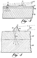
- FIG. 3 is an enlarged top view of a section of the reflector plate of FIG.s 1 and 2.
- FIG. 4 illustrates an alternative ridge shape of the reflector plate of FIG. 3.
- FIG. 5 illustrates an arrangement of illumination sources to change the color of the light emitted very rapidly between 3 colors.
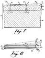
- FIG. 6 is a top view of an alternative illumination system that can produce two sets of blinking lines.
- FIG. 7 is an enlarged top view of the reflector plate shown in FIG. 6.
- FIG. 8 is an alternative means of illuminating two dimensional displays.
- the basic transmissive display of this invention has an improved illumination system which comprises:
- the illumination system for an autostereoscopic display of the type described in US patents 4,717,949 has 2 sub systems: the 2-D illumination system and the 3-D illumination system. The two systems are shown in FIG. 1.
- a bright fluorescent aperture lamp 41 which lacks a phosphor coating along a thin aperture 42 running parallel to its length, is used as a light source.
- These lamps are easily made and common, being used in such devices as copiers and as sources of directed lighting for static displays.
- the lamp source may also be a line of fiber optic strands placed side by side or an incandescent light bulb.
- Light exiting the lamp aperture 42 is focused by a lens 43 situated one focal length or more from the line.
- a holder 44 can be used to hold the lens 43 and aperture lamp 41 in position relative to one another.
- the preferred lens is cylindrical and extends in length along the entire line of light.
- the cylindrical lens 43 may be substituted by a row of square convex lens.
- the length of the lenses preferably being slightly shorter than or equal to the length of the line of light focused by the lens 43.
- Other devices that emit bright light along a thin line can be used in place of the aperture lamp.
- Examples include specialty single filament incandescent lamps with filaments that do not warp when they are turned on, such as those made by the Gilway Technical Lamp Co., Thin Film Electroluminescent edge emitters, fiber optic line converters, linear flash (including strobe) lamps and a variety of bright lamps shining through a slit.
- the collimated light forms a narrow shaft of light, or light beam, 45 in FIG. 2.
- the cylindrical lens 43 and aperture lamp 41 are angled with respect to a flat rectangular reflector plate 46 in such a manner that the shaft of light coming out of cylindrical lens 43 falls across the entire rear surface of reflector plate 46, as shown in FIG. 2.
- FIG. 3 A magnified view of a cross section of reflector plate 46 is shown in FIG. 3.
- the plate is made up of three layers 47, 48, 49.
- the first layer 47 on the side that the light from the cylindrical lens falls on to, is very thin, generally no more than 0.1 mm thick and is transparent.
- the first layer 47 is made from a plastic material that can be cured (or cross linked) at room temperature to avoid shrinkage and warping.
- a typical plastic composition would be an ultraviolet ray curable potting composition e.g., an epoxy potting composition.
- This layer possesses a large number of v shaped ridges, 10, on its back surface, running parallel to the short (vertical) side and to the light emitting source and the cylindrical lens.
- the height of the ridges is such that, when the collimated light from lines 45 falls across the ridge 10 at the proper angle, then the light that misses the first ridge 10, by passing over it goes on and enters the second ridge 10, and so on across the reflector plate 46, so that nearly all the light falling on plate 46 enters the ridges 10.
- the proper height for the ridges 10 is typically around 1/500th inch (2 mils) (0.05 mm).
- a thin layer of diffusing material 48 is placed directly in front of the ridged layer as shown in FIG. 3.
- the diffusing layer should generally be only a fraction of a millimeter thick.
- the diffusing material should be of the type that achieves diffusion by means of tiny particles suspended in a medium, such as an acrylic composition. Such diffusion layers can be obtained from several suppliers in the United States.
- the diffusing layer 48 Light passing through the diffusing layer 48 is spread out, so that it exits the diffusion layer with directions of travel spread across a wide angle. An observer in front of reflector plate 46 sees a large number of thin bright lines on diffusion layer 48, one in front of each ridge, and furthermore the observer can see the lines from wide angles to the normal of reflector plate 46. In some applications the diffusing layer 48 may be omitted. This omission will result in very bright directional beams of light from each ridge 10, 13 that can only be seen from a narrow viewing angle in front of each ridge 10, 13.
- the preferred and more ordinary construction on the reflector panel 46 of this invention utilizes the diffusing layer 48.
- Diffusion layer 48 is deposited on the third layer 49 which is the structural support member of the reflector plate 46.
- the third layer 49 is a piece of smooth, flat, hard transparent material, such as float glass, which provides structural stability to the reflector plate. If made from glass, this layer 49 should be at least 3 mm thick. Light finally exits from this layer where it is spread out even further, again as shown in FIG. 3, since it is exiting from a medium (glass or plastic) with a higher index of refraction than air. The observer in front of reflector plate 46 sees a large number of thin, bright lines formed by the ridges on the diffusion layer 48.
- FIG. 4 illustrates an alternative ridge shape that can be used to spread the light out and avoid the use of the diffuser.
- each ridge 13 possesses a flat side 14 which faces the lamp 41 and cylindrical lens 43 and a convex curved surface 15 which faces away from the cylindrical lens 43 and lamp 41.
- the cylindrical lens 43 in this case should be placed one focal length from the illuminating line to provide even illumination.
- the opposite side of the ridge 15 is curved and is angled so that all of the light from lamp 41 entering flat side 14 is reflected by curved surface 15 due to total internal reflection. Since surface 15 is curved, the collimated light is also focused into a narrow area 16 in front of the ridge, forming a crude image of line 5 at that point, and then spreads out across a wide angle. This angle should typically be about 40 degrees, which means that the curved surface 15 should subtend an arc of about 20 degrees. Surfaces 15 may be aspherical in shape to evenly distribute light across the reflected angle.
- each ridge 10, 13 in either of the above configurations proceeds to pass through the transmissive image forming surface 44, FIG. 1, which is typically an LCD display. If the observer is situated at the correct distance from the display, and directly in front of it, he or she will see stereoscopic images according to the principles noted above.
- a transmissive display can be replaced by a hard copy emulsion possessing left and right eye strip images in place of the pixel columns containing left and right eye views on the transmissive display, which are further described in US patent 4,717,949.
- the illumination system described above can be used to produce a color image on transmissive display 44 if the light emitting line 5, such as from aperture lamp 41 is caused to emit red light, green light, and blue light in rapid succession, and to repeat this process with a 1/30th second period (or less) for each red, green, and blue cycle to be completed.
- FIG. 5 illustrates a method of producing the red, blue, and green flashing sequence by filtering.
- a rotating filter drum 17 with alternating transparent stripes red 18 green 19 and blue 20 is placed around the lamp 41.
- Opaque areas 21 are placed in the drum between the colored stripes 18, 19, 20 of the filter drum 17.
- the light from lamp 41 passes through the colored stripes 18, 19, 20 in front of the lamp aperture 42 and passes through the cylindrical lens 43 on to the reflector plate (not shown).
- the rotating filter drum 17 may be used as a substitute for the lamp 41 shown in FIG. 1.
- Electronic means is provided to synchronize the color changing lamp drum 17 with transmissive display (not shown) so that when red light 18 is emitted, the red color component of an image or images is displayed on display 44, when the light is green 19, the green component of an image is displayed on display 44, and when the light is blue 20 the blue component of an image is displayed on display 44.
- the changes between image components during which a new image is formed on the display occur during the time that the opaque areas 21 block out the light from the lamp 41.
- the display changes from one image to the next while the opaque areas 21 on the drum 17 block light from the lamp 41.
- the drum 17 should be made to rotate fast enough to cause one set of red, green, and blue stripes to pass in front of the lamp every 1/30th second. Thus, over the 1/30th second cycle, an observer will see a full resolution color image made from its red, green and blue components.
- reflector plate for two dimensional illumination.
- the number of ridges on the plate is doubled, and the spacing between them halved, so that an observer in front of the display sees a bright line situated behind each pixel column with both of his or her eyes.
- This illuminator can also use the three color flashing technique described above to provide full resolution, full color images on a 2-D display.
- the present invention allows for an easy method of changing the screen from 2-D to 3-D by merely changing the illumination between a uniform rear illumination source for 2-D and the bright light lines for 3-D. This is illustrated in FIG. 2.
- an electroluminescent (EL) panel 22 which glows when high frequency alternating electrical potential is placed across it, may be placed in the position shown, far enough behind the reflector plate 48 so that it does not block the shaft of light 45 coming from cylindrical lens 43.
- a switch and electrical connections must be provided to turn off lamp 41 and turn on EL panel 22.
- florescent bulbs at the top and bottom of display 12 that cast their light onto a white surface in the same position as EL panel 18, or onto a diffusing layer 8 or 29, banks of fluorescent bulbs placed behind display 12, and woven mats of fiber optic strands.
- a switch can be provided on the display to simultaneously turn off the 3-D light source(s) and turn on the 2-D light source(s).
- FIG. 8 illustrates an alternative way to provide 2-D illumination.
- a layer of LC (Liquid Crystal), usually smectic, material 35 is sandwiched between two electrode layers 36a, 36b is placed between the reflector plate 46 and the transmissive display 39.
- This LC material lets light pass through it undisturbed when an electrical voltage is applied across the material, but it scatters light when the electricity is turned off.
- the electric current across the liquid crystal layer 35 is turned on, allowing the viewer to see the bright lines cast by reflector plate 46.
- the electric current across LC layer 35 is turned off, so that the layer scatters the light from the lines.
- the observer then sees uniform illumination across liquid crystal layer 35, and sees all of the pixels in the transmissive display 39 with both eyes, allowing the observer to comfortably see full resolution 2-D images.
- a similar reflector plate and lamp configuration can be used to provide two sets of blinking lines in order to provide full resolution for each eye when viewing in 3-D.
- a method of presenting full resolution to each eye in 3-D mode is by means of two sets of blinking lines.
- an electronic display unit for autostereoscopic viewing or two dimensional high resolution viewing having (a) a surface that is capable of emitting light from two or more sets of sites, (b) means of causing each set to blink on and then off in succession, one set after the other, and to repeat this process continuously whenever the unit is turned on and (c) a light valve in front of and parallel to said surface, said light valve having individual picture elements on its surface, the light valve being capable of displaying a different set of images every time a different set of light emitting sites flash on.
- FIG.s 6 and 7. This configuration is illustrated in FIG.s 6 and 7.
- two lamps 23, 24 are shown at each side of a reflector plate 27. These lamps 23, 24 are parallel to the sides of plate 27 and in line with each other. Lenses are placed in front of and parallel to the lamps. The lamps alternate in casting bursts of light across the reflector panel.
- cylindrical lenses 25, 26 are placed in front of the lamps 23, 24 and are parallel to them.
- the lamps 23, 24 should be of the linear strobe lamp type that are designed for repetitive flashing of very short bursts of light. Lamps 23, 24 are caused to alternately flash on and off, so that lamp 23 flashes on while lamp 24 is off, and visa versa.
- the flashing rate should be steady, with an equal amount of time, generally no more than 1/60th second, between flashes.
- the flashing is controlled by s synchronizer 34 which also synchronizes the display of images on transmissive display 44.
- reflector plate 27 The construction of reflector plate 27, is nearly identical to that of reflector plate 46 shown in FIG. 7. As before, three layers are used, a transparent ridged layer 28, a diffusion layer 29, and a transparent substrate 30. The main difference in plate 27 is the ridge shape 37. As shown in FIG. 7, each ridge is much wider than previously and each has a flat top 31. As before, the ridges are vertical and parallel to the lamps 23, 24 and to each other. The two sides 32, 33 of the ridges 37 are flat, and can make the same angle with the reflector plate surface as the ridge sides 11, 12 in FIG. 2 - about 52 degrees.
- Light rays 38 from lamp 24 enter the ridges 37 through sides 32, and are reflected into the reflector plate 27 by sides 33 due to total internal reflection, as shown in FIG. 7. As before, the light strikes diffusion layer 29 and its direction of travel is spread through an angle. Light rays 38 from lamp 23 enter sides 33 and are reflected into reflector plate 27 by sides 32. They too pass through diffusion layer 29. As the lamps 23, 24 alternately flash, two sets of alternately flashing lines of light are thus created on diffusion layer 29.
- the tops 31 of ridges 37 may be blackened in order to prevent light from entering them at places other than the flat sides 32, 33 and to prevent light from reflecting off the tops 31 and scattering within the display.
Landscapes
- Physics & Mathematics (AREA)
- Engineering & Computer Science (AREA)
- General Physics & Mathematics (AREA)
- Nonlinear Science (AREA)
- Optics & Photonics (AREA)
- General Engineering & Computer Science (AREA)
- Theoretical Computer Science (AREA)
- Geometry (AREA)
- Signal Processing (AREA)
- Mathematical Physics (AREA)
- Chemical & Material Sciences (AREA)
- Crystallography & Structural Chemistry (AREA)
- Multimedia (AREA)
Applications Claiming Priority (1)
| Application Number | Priority Date | Filing Date | Title |
|---|---|---|---|
| US07/471,926 US5040878A (en) | 1990-01-26 | 1990-01-26 | Illumination for transmissive displays |
Publications (1)
| Publication Number | Publication Date |
|---|---|
| EP0515723A1 true EP0515723A1 (fr) | 1992-12-02 |
Family
ID=23873536
Family Applications (1)
| Application Number | Title | Priority Date | Filing Date |
|---|---|---|---|
| EP91108937A Ceased EP0515723A1 (fr) | 1990-01-26 | 1991-05-31 | Eclairage pour affichage transparent |
Country Status (2)
| Country | Link |
|---|---|
| US (1) | US5040878A (fr) |
| EP (1) | EP0515723A1 (fr) |
Cited By (2)
| Publication number | Priority date | Publication date | Assignee | Title |
|---|---|---|---|---|
| WO2005122595A3 (fr) * | 2004-06-07 | 2006-03-02 | Microsharp Corp Ltd | Ecran de projection par transparence et systeme d'affichage associe |
| EP1328841A4 (fr) * | 2000-07-25 | 2006-05-24 | Scram Technologies Inc | Panneau optique stri , noir |
Families Citing this family (51)
| Publication number | Priority date | Publication date | Assignee | Title |
|---|---|---|---|---|
| US5190370A (en) * | 1991-08-21 | 1993-03-02 | Minnesota Mining And Manufacturing Company | High aspect ratio lighting element |
| US5303322A (en) * | 1992-03-23 | 1994-04-12 | Nioptics Corporation | Tapered multilayer luminaire devices |
| US5528720A (en) * | 1992-03-23 | 1996-06-18 | Minnesota Mining And Manufacturing Co. | Tapered multilayer luminaire devices |
| US6002829A (en) * | 1992-03-23 | 1999-12-14 | Minnesota Mining And Manufacturing Company | Luminaire device |
| US5410345A (en) * | 1992-09-09 | 1995-04-25 | Dimension Technologies, Inc. | Stroboscopic illumination system for video displays |
| US5339179A (en) * | 1992-10-01 | 1994-08-16 | International Business Machines Corp. | Edge-lit transflective non-emissive display with angled interface means on both sides of light conducting panel |
| US6111622A (en) * | 1993-03-12 | 2000-08-29 | Ois Optical Imaging Systems, Inc. | Day/night backlight for a liquid crystal display |
| US5555329A (en) * | 1993-11-05 | 1996-09-10 | Alliesignal Inc. | Light directing optical structure |
| US6129439A (en) * | 1993-11-05 | 2000-10-10 | Alliedsignal Inc. | Illumination system employing an array of multi-faceted microprisms |
| US5428468A (en) * | 1993-11-05 | 1995-06-27 | Alliedsignal Inc. | Illumination system employing an array of microprisms |
| US5396350A (en) * | 1993-11-05 | 1995-03-07 | Alliedsignal Inc. | Backlighting apparatus employing an array of microprisms |
| US5521725A (en) * | 1993-11-05 | 1996-05-28 | Alliedsignal Inc. | Illumination system employing an array of microprisms |
| US5477239A (en) * | 1993-11-12 | 1995-12-19 | Dell Usa, L.P. | Front lighting system for liquid crystal display |
| US5479275A (en) * | 1993-12-03 | 1995-12-26 | Ois Optical Imaging Systems, Inc. | Backlit liquid crystal display with integral collimating, refracting, and reflecting means which refracts and collimates light from a first light source and reflects light from a second light source |
| US5671994A (en) * | 1994-06-08 | 1997-09-30 | Clio Technologies, Inc. | Flat and transparent front-lighting system using microprisms |
| DE19521254A1 (de) * | 1994-06-24 | 1996-01-04 | Minnesota Mining & Mfg | Anzeigesystem mit Helligkeitsverstärkungsfilm |
| US6104452A (en) * | 1994-07-01 | 2000-08-15 | Adaptive Optics Associates, Inc. | Optical illuminator for liquid crystal displays |
| US5682213A (en) * | 1994-07-01 | 1997-10-28 | Adaptive Optics Associates, Inc. | Optical illuminator for liquid crystal displays |
| TW278142B (fr) * | 1994-10-11 | 1996-06-11 | Allied Signal Inc | |
| US5506929A (en) * | 1994-10-19 | 1996-04-09 | Clio Technologies, Inc. | Light expanding system for producing a linear or planar light beam from a point-like light source |
| US5751479A (en) * | 1994-11-18 | 1998-05-12 | Sanyo Electric Co., Ltd. | Three-dimensional display |
| GB2296400A (en) * | 1994-12-16 | 1996-06-26 | Sharp Kk | Autostereoscopic display having a high resolution 2D mode |
| US5608837A (en) * | 1995-05-15 | 1997-03-04 | Clio Technologies, Inc. | Transmissive type display and method capable of utilizing ambient light |
| US5771321A (en) * | 1996-01-04 | 1998-06-23 | Massachusetts Institute Of Technology | Micromechanical optical switch and flat panel display |
| US5818400A (en) * | 1996-04-09 | 1998-10-06 | International Resource Management Inc. | Display device using intersecting optical beams |
| US6137456A (en) * | 1996-07-01 | 2000-10-24 | Corning Incorporated | Electronic display device for simultaneously displaying 2D and 3D images |
| US5897184A (en) * | 1996-07-02 | 1999-04-27 | Dimension Technologies, Inc. | Reduced-thickness backlighter for autostereoscopic display and display using the backlighter |
| AU4316197A (en) * | 1996-09-05 | 1998-03-26 | Wea Manufacturing Inc. | Color printer scanner |
| WO1998055798A2 (fr) * | 1997-06-04 | 1998-12-10 | Simon Jerome H | Lentille ondulee de refraction et de reflexion, utile pour mettre en forme de la lumiere |
| JP3869914B2 (ja) | 1997-09-30 | 2007-01-17 | アルプス電気株式会社 | 照光ユニット及びそれを使用した液晶表示装置 |
| US6166787A (en) * | 1998-03-17 | 2000-12-26 | Motorola, Inc. | Optical display device having prismatic film for enhanced viewing |
| US6157424A (en) * | 1998-03-30 | 2000-12-05 | Dimension Technologies, Inc. | 2D/3D imaging display |
| US6285425B1 (en) | 1998-06-29 | 2001-09-04 | Motorola, Inc. | Ridged reflector for an optical display having a curved and a planar facet for each ridge |
| JP3119241B2 (ja) | 1998-07-01 | 2000-12-18 | 日本電気株式会社 | 液晶表示装置 |
| US6285426B1 (en) | 1998-07-06 | 2001-09-04 | Motorola, Inc. | Ridged reflector having optically transmissive properties for an optical display device |
| US6755534B2 (en) | 2001-08-24 | 2004-06-29 | Brookhaven Science Associates | Prismatic optical display |
| EP1435179B1 (fr) * | 2001-10-02 | 2005-03-23 | SeeReal Technologies GmbH | Ecran plat muni d'un masque dispose devant, destine a la representation spatiale stereoscopique et/ou holographique d'informations |
| FI20070630A7 (fi) * | 2007-08-21 | 2009-02-22 | Supponor Oy | Järjestely säteilyn jakamiseksi |
| TWI359961B (en) * | 2008-04-16 | 2012-03-11 | Univ Nat Taiwan Science Tech | Light-concentrating panel |
| US8096671B1 (en) | 2009-04-06 | 2012-01-17 | Nmera, Llc | Light emitting diode illumination system |
| US8350799B2 (en) | 2009-06-03 | 2013-01-08 | Manufacturing Resources International, Inc. | Dynamic dimming LED backlight |
| US9106925B2 (en) * | 2010-01-11 | 2015-08-11 | Ubiquity Holdings, Inc. | WEAV video compression system |
| US9348174B2 (en) | 2013-03-14 | 2016-05-24 | Manufacturing Resources International, Inc. | Rigid LCD assembly |
| WO2015003130A1 (fr) | 2013-07-03 | 2015-01-08 | Manufacturing Resources International, Inc. | Ensemble de rétroéclairage de guide d'air |
| US10191212B2 (en) | 2013-12-02 | 2019-01-29 | Manufacturing Resources International, Inc. | Expandable light guide for backlight |
| US10527276B2 (en) * | 2014-04-17 | 2020-01-07 | Manufacturing Resources International, Inc. | Rod as a lens element for light emitting diodes |
| US10649273B2 (en) | 2014-10-08 | 2020-05-12 | Manufacturing Resources International, Inc. | LED assembly for transparent liquid crystal display and static graphic |
| US10261362B2 (en) | 2015-09-01 | 2019-04-16 | Manufacturing Resources International, Inc. | Optical sheet tensioner |
| TWM526084U (zh) * | 2016-04-25 | 2016-07-21 | Young Lighting Technology Inc | 顯示裝置 |
| TWM535327U (zh) | 2016-10-11 | 2017-01-11 | 揚昇照明股份有限公司 | 透明顯示裝置 |
| US12429726B1 (en) | 2023-10-02 | 2025-09-30 | Manufacturing Resources International, Inc. | Optical stack with a liquid crystal layer and a micro lens array, electronic display assembly, and related methods |
Citations (4)
| Publication number | Priority date | Publication date | Assignee | Title |
|---|---|---|---|---|
| FR775225A (fr) * | 1933-09-19 | 1934-12-21 | Holophane Sa | Dispositif pour l'éclairage des surfaces diffusantes allongées |
| EP0167721A1 (fr) * | 1984-07-02 | 1986-01-15 | Mitsubishi Rayon Co., Ltd. | Diffuseur de lumière |
| US4937715A (en) * | 1989-01-26 | 1990-06-26 | Kirschner Medical Corporation | Lamp system for operating theatres and the like |
| EP0377309A2 (fr) * | 1989-01-03 | 1990-07-11 | Minnesota Mining And Manufacturing Company | Dispositif d'affichage éclairé par l'arrière |
Family Cites Families (7)
| Publication number | Priority date | Publication date | Assignee | Title |
|---|---|---|---|---|
| US4186431A (en) * | 1978-04-28 | 1980-01-29 | Westinghouse Electric Corp. | Linear light source |
| JPS60107618A (ja) * | 1983-11-16 | 1985-06-13 | Nec Corp | 液晶ライトバルブポジ表示装置 |
| JP2823156B2 (ja) * | 1985-07-23 | 1998-11-11 | キヤノン株式会社 | ディスプレイ装置 |
| US4717949A (en) * | 1986-03-07 | 1988-01-05 | Dimension Technologies, Inc. | Autostereoscopic display with illuminating lines and light valve |
| US4829365A (en) * | 1986-03-07 | 1989-05-09 | Dimension Technologies, Inc. | Autostereoscopic display with illuminating lines, light valve and mask |
| US4822145A (en) * | 1986-05-14 | 1989-04-18 | Massachusetts Institute Of Technology | Method and apparatus utilizing waveguide and polarized light for display of dynamic images |
| US4798448A (en) * | 1988-02-16 | 1989-01-17 | General Electric Company | High efficiency illumination system for display devices |
-
1990
- 1990-01-26 US US07/471,926 patent/US5040878A/en not_active Expired - Fee Related
-
1991
- 1991-05-31 EP EP91108937A patent/EP0515723A1/fr not_active Ceased
Patent Citations (4)
| Publication number | Priority date | Publication date | Assignee | Title |
|---|---|---|---|---|
| FR775225A (fr) * | 1933-09-19 | 1934-12-21 | Holophane Sa | Dispositif pour l'éclairage des surfaces diffusantes allongées |
| EP0167721A1 (fr) * | 1984-07-02 | 1986-01-15 | Mitsubishi Rayon Co., Ltd. | Diffuseur de lumière |
| EP0377309A2 (fr) * | 1989-01-03 | 1990-07-11 | Minnesota Mining And Manufacturing Company | Dispositif d'affichage éclairé par l'arrière |
| US4937715A (en) * | 1989-01-26 | 1990-06-26 | Kirschner Medical Corporation | Lamp system for operating theatres and the like |
Non-Patent Citations (1)
| Title |
|---|
| PATENT ABSTRACTS OF JAPAN, vol. 10, no. 7 (P-419)[2064], 11th January 1986; & JP-A-60 163 023 (SUWA SEIKOSHA) 24-08-1985 * |
Cited By (2)
| Publication number | Priority date | Publication date | Assignee | Title |
|---|---|---|---|---|
| EP1328841A4 (fr) * | 2000-07-25 | 2006-05-24 | Scram Technologies Inc | Panneau optique stri , noir |
| WO2005122595A3 (fr) * | 2004-06-07 | 2006-03-02 | Microsharp Corp Ltd | Ecran de projection par transparence et systeme d'affichage associe |
Also Published As
| Publication number | Publication date |
|---|---|
| US5040878A (en) | 1991-08-20 |
Similar Documents
| Publication | Publication Date | Title |
|---|---|---|
| US5040878A (en) | Illumination for transmissive displays | |
| US5897184A (en) | Reduced-thickness backlighter for autostereoscopic display and display using the backlighter | |
| US8189129B2 (en) | Backlighting system for a 2D/3D autostereoscopic multiview display | |
| JP4861180B2 (ja) | 3dディスプレイ装置用バックライト | |
| US5479275A (en) | Backlit liquid crystal display with integral collimating, refracting, and reflecting means which refracts and collimates light from a first light source and reflects light from a second light source | |
| TWI240058B (en) | Surface light source and LCD display device using such surface light source | |
| US4872750A (en) | Image projection apparatus | |
| US6111622A (en) | Day/night backlight for a liquid crystal display | |
| US6137456A (en) | Electronic display device for simultaneously displaying 2D and 3D images | |
| US4737840A (en) | Color image projection apparatus with a screen including a shield plate, light-emitting layer and diffusion surface to expand viewing range of bright pictures | |
| TW201326982A (zh) | 顯示裝置 | |
| US7903183B2 (en) | Display including backlight operable in 2D and 3D modes | |
| US8388209B2 (en) | Lamp and use thereof | |
| CN103574403A (zh) | 光源装置、显示单元以及电子设备 | |
| CN103032758A (zh) | 光源装置、显示设备和电子设备 | |
| AU2003300219A1 (en) | Arrangement for two-dimensional or three-dimensional representation | |
| TW201331646A (zh) | 照明裝置及具有照明裝置的顯示裝置 | |
| JP2012226294A (ja) | 光源デバイスおよび表示装置、ならびに電子機器 | |
| JP7575852B2 (ja) | 照明デバイス | |
| JPH11149073A (ja) | 面光源装置および液晶表示装置 | |
| CN107144972B (zh) | 一种低串扰、视角可控的裸眼3d显示系统和方法 | |
| US20130088891A1 (en) | Light source device, display unit, and electronic apparatus | |
| JP4483233B2 (ja) | 面光源及び液晶表示装置 | |
| CN1729702B (zh) | 用于二维或三维显示的装置 | |
| US11796863B1 (en) | Multiview display |
Legal Events
| Date | Code | Title | Description |
|---|---|---|---|
| PUAI | Public reference made under article 153(3) epc to a published international application that has entered the european phase |
Free format text: ORIGINAL CODE: 0009012 |
|
| AK | Designated contracting states |
Kind code of ref document: A1 Designated state(s): BE DE DK FR GB IT NL SE |
|
| 17P | Request for examination filed |
Effective date: 19930421 |
|
| 17Q | First examination report despatched |
Effective date: 19950516 |
|
| GRAG | Despatch of communication of intention to grant |
Free format text: ORIGINAL CODE: EPIDOS AGRA |
|
| STAA | Information on the status of an ep patent application or granted ep patent |
Free format text: STATUS: THE APPLICATION HAS BEEN REFUSED |
|
| 18R | Application refused |
Effective date: 19960921 |