EP0515869A2 - Verfahren und Vorrichtung zur Korrektur von Schrägbildern - Google Patents
Verfahren und Vorrichtung zur Korrektur von Schrägbildern Download PDFInfo
- Publication number
- EP0515869A2 EP0515869A2 EP92107534A EP92107534A EP0515869A2 EP 0515869 A2 EP0515869 A2 EP 0515869A2 EP 92107534 A EP92107534 A EP 92107534A EP 92107534 A EP92107534 A EP 92107534A EP 0515869 A2 EP0515869 A2 EP 0515869A2
- Authority
- EP
- European Patent Office
- Prior art keywords
- image
- rotation angle
- computer
- reference line
- point
- Prior art date
- Legal status (The legal status is an assumption and is not a legal conclusion. Google has not performed a legal analysis and makes no representation as to the accuracy of the status listed.)
- Withdrawn
Links
Images



Classifications
-
- G—PHYSICS
- G06—COMPUTING OR CALCULATING; COUNTING
- G06T—IMAGE DATA PROCESSING OR GENERATION, IN GENERAL
- G06T3/00—Geometric image transformations in the plane of the image
- G06T3/60—Rotation of whole images or parts thereof
- G06T3/608—Rotation of whole images or parts thereof by skew deformation, e.g. two-pass or three-pass rotation
Definitions
- the present invention relates generally to the area of computer graphics and, more particularly, to positioning techniques for graphic images.
- Computers have become a powerful tool for the rapid and economic creation of pictures, and are particularly well suited for drafting and publishing tasks.
- CAD computer-aided design
- the CAD user employs a computer with a pointing device (typically a mouse, light pen, digitizer tablet, or the like) to create an electronic description of a drawing in the computer's memory.
- a pointing device typically a mouse, light pen, digitizer tablet, or the like
- DTP desktop publishing
- both text and graphic images are manipulated on a computer screen, much as they are in CAD.
- an output device such as a laser printer or plotter.
- bitmaps are mathematical descriptions of an image. For example, a line may be described by its starting and ending points. A circle may be described by its center and radius.
- bitmaps an image is described as a two dimensional array of bits or pixels (picture elements). By arranging combinations of black and white pixels (0 and 1 bits), an image may be reproduced. This is the technique commonly employed to reproduce images for newspapers and magazines. Bitmaps are almost always rectangular, and if the image itself is not rectangular, then the image must be rendered with a "mask" bitmap that defines the shape of the image.
- bitmap While the bulk of a bitmap comprises the bits themselves, header information is also necessary to define how the bits are interpreted. This includes the height and width of the bitmap (expressed in number of pixels) and color information. In a monochromatic bitmap, one bit in the bitmap corresponds to one pixel on the display. A color bitmap requires multiple bits per pixel. In this case, the header information describes how the multiple bits correspond to particular colors.
- file formats for storing bitmaps Examples include ZSoft's PC Paintbrush (PCX), CompuServe's Graphics Interchange Format (GIF), and Microsoft's Tagged-Image File Format (TIFF).
- bitmaps are used to store real-world images, they usually enter a computer through a scanner or a video frame grabber.
- a scanner converts a photographic image into a bitmapped data file
- a frame grabber converts a video signal (from a video camera or VCR) to a bitmapped data file.
- Bitmaps can also be created by hand using computer "paint" programs, such as Microsoft's Windows Paintbrush program.
- Scanners what are probably by far the most popular method for importing images, employ a light source and photodetectors to "read" images into a computer. Two basic types are available: flatbed and handheld. The operation of each will now be briefly described.
- Flatbed scanners look and operate very much like an ordinary photocopier.
- the user places an image to be scanned upon the flatbed (flat glass).
- the scanner is activated, e.g., by pressing a button.
- the image is then scanned by a light source.
- the scanner focuses the image onto photodetectors which produce binary data representative of the image.
- the data are stored on a computer disk as a binary file, typically in one of the aforementioned file formats.
- the data file is now available to the user for use in application software, such as desktop publishing packages or paint programs.
- handheld scanners substantially all of the scanning system is housed within a single handheld unit. Instead of placing the image to be scanned on a glass surface, as one would do with a photocopier or flatbed scanner, the image is laid face up on a flat surface. The scanner, which includes a roller or wheels, is dragged across the surface of the image. The image is then recorded in a manner similar to that for flatbed systems.
- scanners allow for the easy importation of existing images, they have significant drawbacks. Most commonly, significant artifacts are introduced into an image when it is scanned. Perhaps the most difficult aspect in scanner use is obtaining a straight and accurate scan. Thus, the user must devote a significant, if not substantial, amount of time "cleaning up” the image. Typically, this includes editing the image, usually with a paint program, to erase artifacts and properly align the scanned image.
- Computers have found wide application for the creation and editing of drawings or graphic images.
- a particularly easy technique for creating images is to scan a drawing into a computer using one of the commercially available scanners. Because of artifacts which are introduced during scanning, however, prior art systems have required the computer user to expend significant effort and time editing scanned images, including realigning "skewed" images.
- a method for aligning a graphic image displayed on a computer system comprises selecting a mode for aligning the image; displaying a cursor to indicate a location and said mode; constructing a reference line with said cursor, said reference line having an axis substantially parallel to an element of the graphic image; determining a rotation angle from the dx and dy of said reference line; and rotating the graphic image by an amount equal to said rotation angle.
- a system for processing graphic images constructed in accordance with the principles of the present invention, includes a computer having a memory and a processor; a scanner for capturing images; alignment means for drawing a reference line parallel to an element of the captured image; means for determining dx and dy from the line; means for determining an angle from the dx and dy; means for rotating the image by an amount equal to the angle; and a display for displaying the rotated image.
- Fig. 1A is a block diagram of a computer system in which the present invention may be embodied.
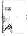
- Fig. 1B represents a display window of the present invention for manipulating images.
- Figs. 2A-E illustrate the deskewing of a bitmapped graphic image.
- Figs. 3A-E illustrate the deskewing of a bitmapped text image.
- Fig. 4 is a flow chart of the deskew method of the present invention.
- Fig. 5 is a flow chart of the deskew rubber band method of the present invention.
- the invention may be embodied on a computer system such as the system 100 of Fig. 1, which comprises a central processor 101, a main memory 102, an I/O controller 103, a screen or display 104, a scanner 105, a mass storage device 106, a keyboard 107, a pointing device 108, and an output device 109.
- the various components of the system 100 communicate through a system bus 110 or similar architecture.
- keyboard 107 and/or pointing device 108 which may be a mouse, a track ball, a digitizing tablet, or the like.
- the computer displays graphic images and other data through screen 104, such as a cathode ray tube.
- a hard copy of the image may be obtained from output device 109, which is typically a printer or a plotter.
- output device 109 which is typically a printer or a plotter.
- an appropriately programmed IBM PC-compatible personal computer available from International Business Machines, Corp. of Armonk, NY
- MS-DOS available from Microsoft, Corp. of Redmond, WA.
- the user imports graphic images with the scanner 105 which may be either a flatbed or handheld scanner (several modes are available from Logitech Corp., Fremont, California).
- the scanner 105 may be either a flatbed or handheld scanner (several modes are available from Logitech Corp., Fremont, California).
- an image is stored as a bitmapped graphic and, thus, may be represented in the computer's memory 102.
- the system 100 provides a window or work space 120 for display on screen 104.
- Window 120 is a rectangular, graphical user interface for viewing and manipulating graphic images.
- Window 120 contains a plurality of menus 140, 150, each having submenus and software tools for use on graphic images.
- menus 140, 150 Of particular interest to the present invention is the Deskew tool 141, which is available from menu 140.
- Window 120 also includes a client area 130 for displaying images, such as the bitmapped graphic image 131.
- the operations of window 120, and the Deskew tool 141 in particular, are best described by the following examples.
- a graphic image 200 such as a bitmap of an ordinary stop sign
- the graphic image has entered the computer via scanner 105.
- image 200 is misaligned, i.e., it is skewed relative to its normal horizontal and vertical orientation. While there are several potential sources of this artifact, probably the most common cause of the skewed image is misalignment between the scanner 105 and the source material during a scan operation.
- the anomaly is corrected as follows.
- the user enters a Deskew mode, for example, by selecting the Deskew option 141 from the menu 140 of Fig. 1B.
- the system displays a Deskew cursor 201, as illustrated in Fig. 2B.
- the user is to draw a "reference line" which matches a linear element on the graphic image 200. Typically, this will be an edge or similar linear attribute.
- the reference line is drawn as follows.
- the user places a starting point 202 at a first location, for example, by "clicking" or actuating a mouse button. This point represents the starting point for the reference line to be drawn.
- the cursor 201 is moved away ("dragged") from starting point 202 so as to define a reference line.
- a temporary or "rubberbanding" line 210 is displayed, thereby providing the user with visual feedback of the orientation of the cursor to the starting point.
- cursor 201 has initially moved away from the starting point in a horizontal direction, however, cursor 201 may move in any direction away from the starting point.
- Rubberbanding technique a form of positioning feedback, is known in the art.
- a user When drawing a line, a user specifies two endpoints. As the user moves from the first endpoint (starting point) to the second (ending point), a temporary or “in transit” line is displayed from the first endpoint to the current cursor position; thus the user can see the lie of the line before he finishes positioning.
- the effect On the computer screen, the effect is that of an elastic or "rubberband” line stretched between the first endpoint and the cursor.
- Rubberbanding See, Newman, W., Principles of Interactive Computer Graphics: Computer Science Series, Second Edition, McGraw Hill, 1979.
- Fig. 2D the user has moved cursor 201 to an ending point 203.
- rubberbanding line 210 indicates that the line (defined by starting point 202 and ending point 203) is parallel to an edge of the graphic image 200.
- the ending point 203 is accepted as the second point for the reference line.
- the absolute position of the line 210 is not important. Instead, only its relative angle is important. Specifically, the angle is measured from the dx and dy of the line; the image is rotated by a complementary angle. Effectively, the corresponding image line (element of the image used for alignment) and everything parallel to it are rotated to effect alignment. If the image line (and hence reference line drawn) is more vertical than horizontal, i.e., in the range of 45° to 135° or 225° to 315°, the image will be rotated to make the line vertical. On the other hand, if the image line is more horizontal, the image will be rotated to make the line horizontal.
- OCR optical character recognition
- Figs. 3A-E a method of deskewing text will be illustrated.
- Fig. 3A there is shown a block of text 300 which is misaligned, i.e., skewed.
- Text 300 will have typically entered the computer through scanner 105.
- the Deskew tool or option 141 is chosen from the menu 140; the system enters the Deskew mode.
- the system 100 displays the Deskew cursor 301, as shown in Fig. 3B.
- a starting point 302 is placed at a first location proximate the text 300.
- this is performed by the user clicking a mouse button (device 108). While the button is still depressed, the mouse is moved or dragged away from the starting point 302.
- system 100 displays a temporary or rubberbanding line 310.
- Rubberbanding line 310 provides constant visual feedback between the starting point 302 and the location of cursor 301 (as previously described hereinabove). While the initial movement of cursor 301 (and orientation of the temporary line) is shown as a vertical line, the cursor is in fact free to move in any direction away from the starting point in order to define a reference line.
- the user releases the mouse button to place an ending point 303 at a second location, as shown in Fig. 3D.
- the system 100 accepts starting point 302 and ending point 303 as the endpoints defining the reference line.
- the text 300 is deskewed, i.e., rotated by an angle corresponding to the angle of the reference line.
- the deskewed text 350 is displayed on screen 104.
- the text may be processed by optical character recognition (OCR) techniques, as is known in the art.
- OCR optical character recognition
- the deskewed text 350 is supplied, e.g., as a deskewed bitmap, to OCR software. Since the text has been restored to a normal alignment, OCR software may readily recognize individual characters of the text by matching the scanned characters with stored character templates (which themselves are stored only in normal alignment).
- the text is converted into a text file, e.g., an ASCII text file--a well known file format. Once converted, the text may be stored on the computer (e.g., storage 106) and/or otherwise processed (e.g., by a word processor).
- the Deskew routine is the top level routine for the Deskew tool 141.
- the routine is invoked by the Window's message dispatcher when a mouse button is depressed in the Deskew mode.
- the dispatching of messages in an event-based system, such as Windows is known in the art; see, e.g., Petzold, C., Programming Windows, Second Edition, Microsoft Press, 1990, the disclosure of which is hereby incorporated by reference.
- the routine is passed a handle to the current image and the x, y coordinates of the mouse cursor when the mouse button is depressed (starting point).
- step 401 the DeskewRubberband routine is called to get the starting and ending points of the reference line.
- the DeskewRubberband routine (described in more detail hereinbelow) receives the x, y screen coordinates where the mouse button was first depressed (starting point), and returns the x, y coordinates where the mouse button is released (ending point).
- step 402 the two sets of coordinates (starting and ending points) defining the reference line are converted from screen to document coordinates.
- the conversion from screen to document coordinates is dependent upon the current zoom factor and view offset employed.
- the document e.g., image 131
- the document may be displayed at any one of a number of zoom factors, and the display surface 130 may be "panned" (moved in virtual space) to show any part of the document.
- a screen coordinate of 0,0 referencing the top left corner of the window
- docCoord (screenCoord / zoomFactor) + offset; where docCoord is the document coordinates, screenCoord is the screen coordinates, zoomFactor is the current magnification (e.g., 2X), and offset is the document coordinate of the pixel displayed at the top left corner.
- docCoord, screenCoord, and offset each has horizontal (x) and vertical (y) components.
- step 403 the dx and dy are determined.
- step 405 if the rotation angle is less than -45°, then in step 406 90° is added. Otherwise (no at step 405), step 406 is skipped.
- step 407 if the rotation angle is greater than 45°, then 90° is subtracted from the angle at step 408. Otherwise (no at step 407), step 408 is skipped. This ensures that the rotation angle, i.e., the angle that the image is rotated through, is both greater than or equal to -45° and less than or equal to 45°.
- step 409 the image is rotated about its center point by the angle computed from the foregoing steps (rotateAngle).
- the rotation of 2D and 3D images is known in the art; see, e.g., Newman, W., Principles of Interactive Computer Graphics : Computer Science Series, Second Edition, McGraw Hill, 1979, the disclosure of which is hereby incorporated by reference.
- step 410 the screen 104 is updated with the new deskewed image. The routine concludes by returning.
- the routine tracks the cursor as it moves across screen 104 until the mouse button is released (button up). Whenever the cursor is moved, the routine draws a reference line on the screen from the point at which the button was pressed down (starting point) to the current cursor position (ending point). Exclusive-OR (XOR) drawing techniques, which are known in the art, are employed for easy erasure. The method is continued until the mouse button is released (button up), whereupon the routine erases the last drawn line and returns the coordinates of the current cursor position.
- XOR Exclusive-OR
- step 501 the routine gets the current cursor position (starting point), which is where the user first depressed the mouse button.
- step 502 if the current cursor position is different from a previous cursor position (if any), then in step 503 any previous drawn reference line is erased and in step 504 a new reference line is drawn. If the current cursor position is not different from a previous position (no at step 502), then steps 503 and 504 are skipped. If the mouse button is released in step 505 (button up message from Windows), then in step 506 the previously drawn reference line is erased and in step 507 the current coordinates are returned. Otherwise (no at step 505), the routine loops to step 501 to get a new current cursor position.
- Attached hereto is an Appendix containing source code listings providing a description of the invention suitable for use in a general purpose digital computer system, such as an IBM-compatible personal computer.
Landscapes
- Physics & Mathematics (AREA)
- General Physics & Mathematics (AREA)
- Engineering & Computer Science (AREA)
- Theoretical Computer Science (AREA)
- Processing Or Creating Images (AREA)
Applications Claiming Priority (2)
| Application Number | Priority Date | Filing Date | Title |
|---|---|---|---|
| US70751891A | 1991-05-30 | 1991-05-30 | |
| US707518 | 1996-09-04 |
Publications (2)
| Publication Number | Publication Date |
|---|---|
| EP0515869A2 true EP0515869A2 (de) | 1992-12-02 |
| EP0515869A3 EP0515869A3 (en) | 1993-11-24 |
Family
ID=24842035
Family Applications (1)
| Application Number | Title | Priority Date | Filing Date |
|---|---|---|---|
| EP19920107534 Withdrawn EP0515869A3 (en) | 1991-05-30 | 1992-05-04 | Apparatus and method for deskewing images |
Country Status (2)
| Country | Link |
|---|---|
| EP (1) | EP0515869A3 (de) |
| CA (1) | CA2068070A1 (de) |
Cited By (2)
| Publication number | Priority date | Publication date | Assignee | Title |
|---|---|---|---|---|
| CN102506769A (zh) * | 2011-11-15 | 2012-06-20 | 益海芯电子技术江苏有限公司 | 旋转角度检测方法 |
| EP3388989A1 (de) * | 2017-04-12 | 2018-10-17 | Ricoh Company Ltd. | Realogram-planogram-benutzeroberfläche |
Family Cites Families (2)
| Publication number | Priority date | Publication date | Assignee | Title |
|---|---|---|---|---|
| JPS63109650A (ja) * | 1986-10-27 | 1988-05-14 | Sharp Corp | 画像読取装置 |
| JP2854860B2 (ja) * | 1987-10-30 | 1999-02-10 | ファナック株式会社 | 形状取り付け方法 |
-
1992
- 1992-05-04 EP EP19920107534 patent/EP0515869A3/en not_active Withdrawn
- 1992-05-06 CA CA 2068070 patent/CA2068070A1/en not_active Abandoned
Cited By (3)
| Publication number | Priority date | Publication date | Assignee | Title |
|---|---|---|---|---|
| CN102506769A (zh) * | 2011-11-15 | 2012-06-20 | 益海芯电子技术江苏有限公司 | 旋转角度检测方法 |
| CN102506769B (zh) * | 2011-11-15 | 2013-11-20 | 益海芯电子技术江苏有限公司 | 旋转角度检测方法 |
| EP3388989A1 (de) * | 2017-04-12 | 2018-10-17 | Ricoh Company Ltd. | Realogram-planogram-benutzeroberfläche |
Also Published As
| Publication number | Publication date |
|---|---|
| EP0515869A3 (en) | 1993-11-24 |
| CA2068070A1 (en) | 1992-12-01 |
Similar Documents
| Publication | Publication Date | Title |
|---|---|---|
| AU662947B2 (en) | Apparatus and methods for automerging images | |
| US7131061B2 (en) | System for processing electronic documents using physical documents | |
| CN1499440B (zh) | 用于产生图像以用于识别对象相对于该图像的位置的方法 | |
| US5511148A (en) | Interactive copying system | |
| US6999061B2 (en) | Electronic whiteboard system | |
| JP2806961B2 (ja) | 画像符号化方法 | |
| US7870501B2 (en) | Method for hollow selection feedback | |
| US7971149B2 (en) | Method for comparing an original document and a modified document using user-selected reference point sets | |
| EP1901233A2 (de) | Verfahren zur Akkumulierung von Bildsegmenten bei der Darstellung von Dokumenten | |
| JP2001175807A (ja) | テキスト領域選択方法 | |
| Newman et al. | CamWorks: A Video-Based Tool for Efficient Capture from Paper Source Documents. | |
| US6771266B2 (en) | Method and apparatus for improving the appearance of digitally represented handwriting | |
| JPH10508127A (ja) | テキストのビットマップ・イメージからテキストの部分を自動的に指定する方法及び装置 | |
| RU2347271C2 (ru) | Глобальная локализация путем быстрого согласования изображений | |
| US5636336A (en) | Graphics processing unit for use with a stylus pen and tablet, and method therefore | |
| EP0515869A2 (de) | Verfahren und Vorrichtung zur Korrektur von Schrägbildern | |
| US5907665A (en) | Method and apparatus for transforming image data | |
| JP5618719B2 (ja) | 画像処理装置、その方法およびプログラム | |
| US8990681B2 (en) | Method for aligning a modified document and an original document for comparison and difference highlighting | |
| JP2003046746A (ja) | 画像処理方法及び画像処理装置 | |
| JPH0355867B2 (de) | ||
| Haigh | Developing rectification programs for small computers | |
| Ryman | Personal systems image application architecture: lessons learned from the ImagEdit program | |
| JP2578965B2 (ja) | 図形処理装置 | |
| JPS6324367A (ja) | 画像処理方法 |
Legal Events
| Date | Code | Title | Description |
|---|---|---|---|
| PUAI | Public reference made under article 153(3) epc to a published international application that has entered the european phase |
Free format text: ORIGINAL CODE: 0009012 |
|
| AK | Designated contracting states |
Kind code of ref document: A2 Designated state(s): DE FR GB IT |
|
| PUAL | Search report despatched |
Free format text: ORIGINAL CODE: 0009013 |
|
| AK | Designated contracting states |
Kind code of ref document: A3 Designated state(s): DE FR GB IT |
|
| STAA | Information on the status of an ep patent application or granted ep patent |
Free format text: STATUS: THE APPLICATION IS DEEMED TO BE WITHDRAWN |
|
| 18D | Application deemed to be withdrawn |
Effective date: 19940525 |