EP0516005A1 - Charrue comportant un dispositif de sécurité pour l'age - Google Patents
Charrue comportant un dispositif de sécurité pour l'age Download PDFInfo
- Publication number
- EP0516005A1 EP0516005A1 EP92108724A EP92108724A EP0516005A1 EP 0516005 A1 EP0516005 A1 EP 0516005A1 EP 92108724 A EP92108724 A EP 92108724A EP 92108724 A EP92108724 A EP 92108724A EP 0516005 A1 EP0516005 A1 EP 0516005A1
- Authority
- EP
- European Patent Office
- Prior art keywords
- grindel
- pressure
- bolt
- spindle
- toggle lever
- Prior art date
- Legal status (The legal status is an assumption and is not a legal conclusion. Google has not performed a legal analysis and makes no representation as to the accuracy of the status listed.)
- Granted
Links
Images


Classifications
-
- A—HUMAN NECESSITIES
- A01—AGRICULTURE; FORESTRY; ANIMAL HUSBANDRY; HUNTING; TRAPPING; FISHING
- A01B—SOIL WORKING IN AGRICULTURE OR FORESTRY; PARTS, DETAILS, OR ACCESSORIES OF AGRICULTURAL MACHINES OR IMPLEMENTS, IN GENERAL
- A01B61/00—Devices for, or parts of, agricultural machines or implements for preventing overstrain
- A01B61/04—Devices for, or parts of, agricultural machines or implements for preventing overstrain of the connection between tools and carrier beam or frame
- A01B61/044—Devices for, or parts of, agricultural machines or implements for preventing overstrain of the connection between tools and carrier beam or frame the connection enabling a yielding pivoting movement around a substantially horizontal and transverse axis
- A01B61/046—Devices for, or parts of, agricultural machines or implements for preventing overstrain of the connection between tools and carrier beam or frame the connection enabling a yielding pivoting movement around a substantially horizontal and transverse axis the device including an energy accumulator for restoring the tool to its working position
- A01B61/048—Devices for, or parts of, agricultural machines or implements for preventing overstrain of the connection between tools and carrier beam or frame the connection enabling a yielding pivoting movement around a substantially horizontal and transverse axis the device including an energy accumulator for restoring the tool to its working position the connection or the energy accumulator being active in two opposite directions, e.g. for reversible plows
Definitions
- the invention relates to a grind overload protection for plows, in which the grind and its swivel joint are arranged on the plow frame in a common horizontal plane, with a working memory arranged in a tubular grind, a toggle lever system fastened between the plow frame and the grinder, including components for power transmission from the working memory to Knee joint and a stop that limits the downward deflection of the spindle as well as an adjustment device for the knee lever system.
- EP 37 848 discloses a spindle overload protection for bed plows.
- the plow body is lifted and inserted by means of a compression spring arranged in the tubular shaft, which is supported on the plow frame by a toggle lever system.
- the arrangement of the toggle lever arms between the spindle and plow frame makes it possible to apply the compression spring essentially in the longitudinal direction of the spindle, but the articulation point of the compression spring lies on a vertical circular path. Therefore, when the plow body is lifted out, the compression spring can tilt in the spindle.
- the toggle lever system At its junction with the plow frame, the toggle lever system has a device for setting the triggering force for the overload protection, which additionally increases the construction effort.
- the object of the invention is therefore to provide a compact and reliable overload protection device for plows.
- the toggle lever system has a knee joint which can be swung out in the direction of the grind.
- a holding and adjusting device on the side facing away from the grind of the rotatable toggle head of the rear toggle arm of the Knee lever system, ie arranged above the rear knee lever arm during bed plow.
- the holding and adjusting device is attached to the spindle.
- a force transmission element is arranged between the knee joint bolt and a pressure bolt mounted on the working memory in the spindle.
- the toggle lever system consists of two front and two likewise arranged rear toggle lever arms which are arranged next to one another in pairs and which are connected to one another like a chain link by means of the knee joint bolt.
- the holding and adjusting device consists of an adjusting screw fastened to the spindle head and a stop arranged on the rear toggle lever arm, against which the adjusting screw rests in the working position.
- a cover for the moving parts of the overload protection is arranged on the spindle head.
- a pressure plate is mounted between the knee joint bolt and the pressure bolt and is mounted so as to swing about a bolt on the head of the spindle.
- the pressure plate has two approximately opposite guideways, each of which the knee joint bolt or the pressure bolt abut non-positively. Both sides of the spindle each have an elongated guide hole for receiving the pressure bolt.
- the force transmission element arranged between the knee joint pin and the pressure pin is designed as a positive strut.
- a carriage with rollers is arranged in the grind between the pressure pin and the working memory.
- the pressure strut on the bed plow is open to the rear Provide pocket in which the pressure pin is stored.
- the plow body In the working position, the plow body is held in its lower end position by means of the toggle lever system. Since the rear toggle arm also rests on the adjusting screw attached to the spindle in the transport position, the power of the working memory is supported there. Thus, the grind hangs only with its own weight and the power of the working memory on the toggle lever system and the swivel joint of the grind, which makes a special stop underneath the grind to fix it in the working position unnecessary.
- the toggle lever or the grinder in its zero position is also adjusted with the adjusting screw. Their arrangement above the stop on the rear toggle lever arm has proven to be advantageous, since in this way no additional installation space is required on the spindle.
- the pressure plate is pressed backwards and also moves the pressure pin backwards. In this way, the preloaded working memory is further compressed.
- the front toggle arms are pushed backwards and push the carriage backwards via the pressure pin.
- the preloaded working memory is thus also charged.
- the working memory presses the respective power transmission element and thus the toggle lever system back into its starting position, so that the plow body reaches its working position again.
- the front toggle arms each have an elongated hole for receiving the hinge pin on the plow frame and the pressure struts each have an elongated hole for receiving the pressure pin.
- the pivot pin becomes the pivot pin of the front toggle lever arms of the upper toggle lever system is pressed into its rear end position in the elongated holes, during which the articulation pin of the front toggle lever arms of the lower toggle lever system slides in the elongated holes in the direction of its front end position depending on the intensity of the deflection.
- the lower toggle lever system is stretched in relation to its position in the working position and thus enables the distance between the pressure bolt and the swivel joint of the spindle and thus its deflection.
- the positive connection of the pressure strut and pressure pin a further increase in the possible deflection of the spindle is achieved by arranging the pressure pin in an elongated hole in the pressure strut.
- the non-positive connection between the pressure plate and the pressure pin in the first embodiment of the invention in the spindle enables the overload protection to be installed relatively easily.
- the working memory is inserted from behind and the pressure plate from the front into the spindle until they are in contact with the pressure pin.
- This particular advantage of the solution according to the invention is also ensured in the second embodiment by the pocket of the pressure strut which is open to the rear during the bed plow.
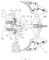
- the other side of the pressure plate 6 is held by the pressure pin 18 on its guide track 17 designed as a support surface. This is located in two guide slots 19 formed laterally in the shaft 2 and is loaded by the working memory 20 designed as a compression spring (FIGS. 3, 4).
- a plow 21 above the toggle lever arms 11 has a stop 21 and an adjusting screw 22 is arranged on the spindle head 9.
- the stop 21 and the adjusting screw 22 acting on it together form the holding and adjusting device 23.
- a cover 24 for the moving parts of the overload protection device is arranged on the spindle head 9.
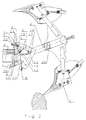
- the force transmission element 7 is designed as a pressure strut 25 which is arranged in a form-fitting manner between the knee joint bolt 13 and the pressure bolt 18.
- a pocket 26 is formed which receives the pressure pin 18.
- a carriage 27 with rollers 28 is arranged in the shaft 2 between the pressure pin 18 and the pressure spring 20 (FIG. 7).
- the overload protection When used in a rotary plow, the overload protection is equipped with a second toggle lever system 5, which is arranged in mirror image to the horizontal plane 29 through the swivel joint 4 of the spindle 2.
- the holding and adjusting device 23 and the cover 24 are likewise arranged in a mirror image of this horizontal plane 29.
- the front toggle arms 10 each have an elongated hole 30 for receiving the hinge pin 14 on the plow frame 3 (FIG. 1).
- the pressure struts 25 in the rotary plow are each provided with an elongated hole 31 for receiving the pressure pin 18 (FIG. 5).
- the plow body 1 In the working position, the plow body 1 is in its lower end position and the spindle 2 is supported on the plow frame 3 via the toggle lever system 5 or its front toggle lever arms 10 and the hinge pin 14.
- the front toggle lever arms 10 are held by means of the knee joint bolt 13 and the rear toggle lever arms 11 resting on the holding and adjusting device 23.
- the end position of the spindle 2 is adjusted by adjusting the adjusting screw 22 (FIG. 1).
- the spindle 2 moves upward about its swivel joint 4.
- the knee joint pin 13 is moved backwards by the action of the front toggle arms 10 on a path predetermined by the rear toggle arms 11.
- the pressure plate 6 is pushed backwards.
- the knee-joint pin 13 slides on the rolling surface 16 of the pressure plate 6, and this, with its support surface 17, also displaces the pressure pin 18 in the elongated guide holes 19 to the rear. In this way, the compression spring 20 is compressed.
- the compression spring 20 presses the pressure plate 6, the knee joint pin 13 and thus the toggle lever system 5 back into its end position and thus brings the plow body 1 back into the working position (FIG. 2).
- this extension of the lower toggle lever system 5 is increased in the second exemplary embodiment by the mobility of its pressure strut 25 in the elongated hole 31 around the pressure bolt 28 (FIG. 6).
- the compression spring 20 is used to mount the overload protection inserted from behind and the pressure plate 6 from the front into the shaft 2 until both abut the pressure pin 18. This simple installation option is also ensured in the case of the plow in the second exemplary embodiment by the pocket 26 of the pressure strut 25 which is open at the rear.
Landscapes
- Life Sciences & Earth Sciences (AREA)
- Engineering & Computer Science (AREA)
- Mechanical Engineering (AREA)
- Soil Sciences (AREA)
- Environmental Sciences (AREA)
- Soil Working Implements (AREA)
- Transition And Organic Metals Composition Catalysts For Addition Polymerization (AREA)
- Jib Cranes (AREA)
- Acyclic And Carbocyclic Compounds In Medicinal Compositions (AREA)
- Heterocyclic Carbon Compounds Containing A Hetero Ring Having Oxygen Or Sulfur (AREA)
- Cleaning Of Streets, Tracks, Or Beaches (AREA)
- Measurement Of Force In General (AREA)
- Rod-Shaped Construction Members (AREA)
- Load-Engaging Elements For Cranes (AREA)
- Transmission Devices (AREA)
- Holders For Apparel And Elements Relating To Apparel (AREA)
- Mechanical Treatment Of Semiconductor (AREA)
- Lifting Devices For Agricultural Implements (AREA)
- Supports For Pipes And Cables (AREA)
Applications Claiming Priority (2)
| Application Number | Priority Date | Filing Date | Title |
|---|---|---|---|
| DE4117949 | 1991-05-31 | ||
| DE4117949A DE4117949C2 (de) | 1991-05-31 | 1991-05-31 | Mechanische Überlastsicherung für Beet- und Drehpflüge |
Publications (2)
| Publication Number | Publication Date |
|---|---|
| EP0516005A1 true EP0516005A1 (fr) | 1992-12-02 |
| EP0516005B1 EP0516005B1 (fr) | 1995-10-04 |
Family
ID=6432946
Family Applications (1)
| Application Number | Title | Priority Date | Filing Date |
|---|---|---|---|
| EP92108724A Expired - Lifetime EP0516005B1 (fr) | 1991-05-31 | 1992-05-23 | Charrue comportant un dispositif de sécurité pour l'age |
Country Status (7)
| Country | Link |
|---|---|
| EP (1) | EP0516005B1 (fr) |
| AT (1) | ATE128603T1 (fr) |
| CS (1) | CS163792A3 (fr) |
| DE (2) | DE4117949C2 (fr) |
| DK (1) | DK0516005T3 (fr) |
| HU (1) | HUT66004A (fr) |
| PL (1) | PL294725A1 (fr) |
Cited By (4)
| Publication number | Priority date | Publication date | Assignee | Title |
|---|---|---|---|---|
| WO2016075718A1 (fr) * | 2014-11-11 | 2016-05-19 | Er.Mo Spa | Charrue réversible ayant un système de sécurité amélioré |
| CN106612631A (zh) * | 2016-12-30 | 2017-05-10 | 南漳县恒达机械制造销售有限公司 | 开沟犁 |
| CN110637524A (zh) * | 2019-10-31 | 2020-01-03 | 郑州市龙丰农业机械装备制造有限公司 | 具有过载保护的翻转犁及其过载保护方法 |
| CN115606337A (zh) * | 2022-11-04 | 2023-01-17 | 新疆农垦科学院 | 一种犁耕机械防过载自动避障机构 |
Families Citing this family (3)
| Publication number | Priority date | Publication date | Assignee | Title |
|---|---|---|---|---|
| DE102005020921B3 (de) * | 2005-05-04 | 2007-01-25 | Lemken Gmbh & Co. Kg | Drehpflug mit Überlastsicherung |
| DK1856965T3 (da) | 2006-05-19 | 2009-09-28 | Lemken Gmbh & Co Kg | Vendeplov med overbelastningssikring |
| CN110583108A (zh) * | 2019-09-25 | 2019-12-20 | 周能为 | 一种应用于多环境翻土用的犁具 |
Citations (3)
| Publication number | Priority date | Publication date | Assignee | Title |
|---|---|---|---|---|
| FR2301165A1 (fr) * | 1975-02-20 | 1976-09-17 | Fenet Gilbert | Charrue munie d'un dispositif de securite |
| EP0037848A1 (fr) * | 1980-04-10 | 1981-10-21 | Rabewerk Heinrich Clausing | Dispositif de sécurité pour charrues simples |
| EP0229484A1 (fr) * | 1985-12-03 | 1987-07-22 | Ransomes Sims & Jefferies, Public Limited Company | Charrues réversibles |
-
1991
- 1991-05-31 DE DE4117949A patent/DE4117949C2/de not_active Expired - Fee Related
-
1992
- 1992-05-23 DK DK92108724.3T patent/DK0516005T3/da active
- 1992-05-23 AT AT92108724T patent/ATE128603T1/de not_active IP Right Cessation
- 1992-05-23 EP EP92108724A patent/EP0516005B1/fr not_active Expired - Lifetime
- 1992-05-23 DE DE59203879T patent/DE59203879D1/de not_active Expired - Fee Related
- 1992-05-27 HU HU9201764A patent/HUT66004A/hu unknown
- 1992-05-28 PL PL29472592A patent/PL294725A1/xx unknown
- 1992-05-29 CS CS921637A patent/CS163792A3/cs unknown
Patent Citations (3)
| Publication number | Priority date | Publication date | Assignee | Title |
|---|---|---|---|---|
| FR2301165A1 (fr) * | 1975-02-20 | 1976-09-17 | Fenet Gilbert | Charrue munie d'un dispositif de securite |
| EP0037848A1 (fr) * | 1980-04-10 | 1981-10-21 | Rabewerk Heinrich Clausing | Dispositif de sécurité pour charrues simples |
| EP0229484A1 (fr) * | 1985-12-03 | 1987-07-22 | Ransomes Sims & Jefferies, Public Limited Company | Charrues réversibles |
Cited By (4)
| Publication number | Priority date | Publication date | Assignee | Title |
|---|---|---|---|---|
| WO2016075718A1 (fr) * | 2014-11-11 | 2016-05-19 | Er.Mo Spa | Charrue réversible ayant un système de sécurité amélioré |
| CN106612631A (zh) * | 2016-12-30 | 2017-05-10 | 南漳县恒达机械制造销售有限公司 | 开沟犁 |
| CN110637524A (zh) * | 2019-10-31 | 2020-01-03 | 郑州市龙丰农业机械装备制造有限公司 | 具有过载保护的翻转犁及其过载保护方法 |
| CN115606337A (zh) * | 2022-11-04 | 2023-01-17 | 新疆农垦科学院 | 一种犁耕机械防过载自动避障机构 |
Also Published As
| Publication number | Publication date |
|---|---|
| DE4117949C2 (de) | 1995-09-21 |
| HUT66004A (en) | 1994-08-29 |
| HU9201764D0 (en) | 1992-08-28 |
| DE59203879D1 (de) | 1995-11-09 |
| PL294725A1 (en) | 1992-12-14 |
| EP0516005B1 (fr) | 1995-10-04 |
| DE4117949A1 (de) | 1992-12-03 |
| CS163792A3 (en) | 1992-12-16 |
| DK0516005T3 (da) | 1995-11-27 |
| ATE128603T1 (de) | 1995-10-15 |
Similar Documents
| Publication | Publication Date | Title |
|---|---|---|
| EP0097347B1 (fr) | Châssis porte-outils | |
| EP0124646B1 (fr) | Appareil pour tasser la neige | |
| DE2428917C3 (de) | Bodenbearbeitungsgerät | |
| DE2801116B2 (de) | Klappbarer Geräteträger mit zwei Werkzeugtragrahmen | |
| DE7523511U (de) | Aufsatteldrehpflug mit einer ueberlastsicherung der verbindung zwischen bodenbearbeitungswerkzeugen und ihren tragrahmen | |
| DE1557738C3 (fr) | ||
| EP0516005B1 (fr) | Charrue comportant un dispositif de sécurité pour l'age | |
| DE1557738B2 (de) | Gesteinauslöser für einen an einem Schlepper anbaubaren Pflug | |
| DE4117947A1 (de) | Hydromechanische ueberlastsicherung fuer beet- und drehpfluege | |
| DE69412686T2 (de) | Fahrbares Stapelgerät für Ballen | |
| EP0556459A1 (fr) | Charrue réversible attelable ou accrochable | |
| DE2615497C3 (de) | Zugdeichselanordnung für schleppergezogene landwirtschaftliche Maschine | |
| EP0383013A2 (fr) | Rouleau compacteur | |
| EP0037848A1 (fr) | Dispositif de sécurité pour charrues simples | |
| DE2422986C3 (fr) | ||
| DE69101201T2 (de) | Dreipunktaufhängung eines Schleppers. | |
| EP1008550B1 (fr) | Agencement mécanique pour limiter le mouvement de plate-formes de travail | |
| DE9007819U1 (de) | Mähmaschine | |
| DE2422986A1 (de) | Ueberlastsicherung fuer einen um 180 grad schwenkbaren ein- oder mehrscharigen drehpflug | |
| DE3419960A1 (de) | Stein- und ueberlastsicherung fuer pfluege u.dgl. | |
| DE9315877U1 (de) | Heuwerbungsmaschine | |
| DE2606806B1 (de) | Mobile richtvorrichtung, insbesondere fuer kraftfahrzeug-karosserien | |
| DE2950551C2 (de) | Steinsicherung | |
| CH643981A5 (de) | Steinsicherung fuer drehpfluege. | |
| DE9202278U1 (de) | Aufsattel- oder Anhänge-Drehpflug |
Legal Events
| Date | Code | Title | Description |
|---|---|---|---|
| PUAI | Public reference made under article 153(3) epc to a published international application that has entered the european phase |
Free format text: ORIGINAL CODE: 0009012 |
|
| AK | Designated contracting states |
Kind code of ref document: A1 Designated state(s): AT CH DE DK FR GB IT LI NL SE |
|
| 17P | Request for examination filed |
Effective date: 19930219 |
|
| 17Q | First examination report despatched |
Effective date: 19940321 |
|
| RAP1 | Party data changed (applicant data changed or rights of an application transferred) |
Owner name: BBG BODENBEARBEITUNGSGERAETE LEIPZIG GMBH |
|
| RAP3 | Party data changed (applicant data changed or rights of an application transferred) |
Owner name: BBG BODENBEARBEITUNGSGERAETE LEIPZIG GMBH |
|
| ITF | It: translation for a ep patent filed | ||
| GRAA | (expected) grant |
Free format text: ORIGINAL CODE: 0009210 |
|
| AK | Designated contracting states |
Kind code of ref document: B1 Designated state(s): AT CH DE DK FR GB IT LI NL SE |
|
| REF | Corresponds to: |
Ref document number: 128603 Country of ref document: AT Date of ref document: 19951015 Kind code of ref document: T |
|
| GBT | Gb: translation of ep patent filed (gb section 77(6)(a)/1977) |
Effective date: 19950928 |
|
| REF | Corresponds to: |
Ref document number: 59203879 Country of ref document: DE Date of ref document: 19951109 |
|
| REG | Reference to a national code |
Ref country code: DK Ref legal event code: T3 |
|
| ET | Fr: translation filed | ||
| PGFP | Annual fee paid to national office [announced via postgrant information from national office to epo] |
Ref country code: DE Payment date: 19960731 Year of fee payment: 5 |
|
| PGFP | Annual fee paid to national office [announced via postgrant information from national office to epo] |
Ref country code: GB Payment date: 19960809 Year of fee payment: 5 |
|
| PLBE | No opposition filed within time limit |
Free format text: ORIGINAL CODE: 0009261 |
|
| STAA | Information on the status of an ep patent application or granted ep patent |
Free format text: STATUS: NO OPPOSITION FILED WITHIN TIME LIMIT |
|
| PGFP | Annual fee paid to national office [announced via postgrant information from national office to epo] |
Ref country code: FR Payment date: 19960810 Year of fee payment: 5 |
|
| PGFP | Annual fee paid to national office [announced via postgrant information from national office to epo] |
Ref country code: SE Payment date: 19960822 Year of fee payment: 5 Ref country code: AT Payment date: 19960822 Year of fee payment: 5 |
|
| PGFP | Annual fee paid to national office [announced via postgrant information from national office to epo] |
Ref country code: DK Payment date: 19960823 Year of fee payment: 5 Ref country code: CH Payment date: 19960823 Year of fee payment: 5 |
|
| PGFP | Annual fee paid to national office [announced via postgrant information from national office to epo] |
Ref country code: NL Payment date: 19960828 Year of fee payment: 5 |
|
| 26N | No opposition filed | ||
| PG25 | Lapsed in a contracting state [announced via postgrant information from national office to epo] |
Ref country code: GB Effective date: 19970523 Ref country code: DK Free format text: LAPSE BECAUSE OF NON-PAYMENT OF DUE FEES Effective date: 19970523 Ref country code: AT Effective date: 19970523 |
|
| REG | Reference to a national code |
Ref country code: DK Ref legal event code: EBP |
|
| PG25 | Lapsed in a contracting state [announced via postgrant information from national office to epo] |
Ref country code: SE Effective date: 19970524 |
|
| PG25 | Lapsed in a contracting state [announced via postgrant information from national office to epo] |
Ref country code: LI Free format text: LAPSE BECAUSE OF NON-PAYMENT OF DUE FEES Effective date: 19970531 Ref country code: CH Free format text: LAPSE BECAUSE OF NON-PAYMENT OF DUE FEES Effective date: 19970531 |
|
| PG25 | Lapsed in a contracting state [announced via postgrant information from national office to epo] |
Ref country code: NL Effective date: 19971201 |
|
| GBPC | Gb: european patent ceased through non-payment of renewal fee |
Effective date: 19970523 |
|
| REG | Reference to a national code |
Ref country code: CH Ref legal event code: PL |
|
| PG25 | Lapsed in a contracting state [announced via postgrant information from national office to epo] |
Ref country code: FR Free format text: LAPSE BECAUSE OF NON-PAYMENT OF DUE FEES Effective date: 19980130 |
|
| EUG | Se: european patent has lapsed |
Ref document number: 92108724.3 |
|
| NLV4 | Nl: lapsed or anulled due to non-payment of the annual fee |
Effective date: 19971201 |
|
| PG25 | Lapsed in a contracting state [announced via postgrant information from national office to epo] |
Ref country code: DE Free format text: LAPSE BECAUSE OF NON-PAYMENT OF DUE FEES Effective date: 19980203 |
|
| REG | Reference to a national code |
Ref country code: FR Ref legal event code: ST |
|
| PG25 | Lapsed in a contracting state [announced via postgrant information from national office to epo] |
Ref country code: IT Free format text: LAPSE BECAUSE OF NON-PAYMENT OF DUE FEES;WARNING: LAPSES OF ITALIAN PATENTS WITH EFFECTIVE DATE BEFORE 2007 MAY HAVE OCCURRED AT ANY TIME BEFORE 2007. THE CORRECT EFFECTIVE DATE MAY BE DIFFERENT FROM THE ONE RECORDED. Effective date: 20050523 |