EP0516058A2 - Système de transmission multiplexé - Google Patents
Système de transmission multiplexé Download PDFInfo
- Publication number
- EP0516058A2 EP0516058A2 EP92108870A EP92108870A EP0516058A2 EP 0516058 A2 EP0516058 A2 EP 0516058A2 EP 92108870 A EP92108870 A EP 92108870A EP 92108870 A EP92108870 A EP 92108870A EP 0516058 A2 EP0516058 A2 EP 0516058A2
- Authority
- EP
- European Patent Office
- Prior art keywords
- video signal
- signal
- remote control
- frequency
- modulated
- Prior art date
- Legal status (The legal status is an assumption and is not a legal conclusion. Google has not performed a legal analysis and makes no representation as to the accuracy of the status listed.)
- Granted
Links
Images


Classifications
-
- H—ELECTRICITY
- H04—ELECTRIC COMMUNICATION TECHNIQUE
- H04N—PICTORIAL COMMUNICATION, e.g. TELEVISION
- H04N7/00—Television systems
- H04N7/10—Adaptations for transmission by electrical cable
-
- H—ELECTRICITY
- H04—ELECTRIC COMMUNICATION TECHNIQUE
- H04N—PICTORIAL COMMUNICATION, e.g. TELEVISION
- H04N7/00—Television systems
- H04N7/08—Systems for the simultaneous or sequential transmission of more than one television signal, e.g. additional information signals, the signals occupying wholly or partially the same frequency band, e.g. by time division
- H04N7/081—Systems for the simultaneous or sequential transmission of more than one television signal, e.g. additional information signals, the signals occupying wholly or partially the same frequency band, e.g. by time division the additional information signals being transmitted by means of a subcarrier
Definitions
- the present invention relates to a multiplex transmission system and an apparatus therefor for transmitting multiplexed signals including a video signal, a control signal, a power supply, etc.
- a transmission system as disclosed in Japanese Utility Model Publication No. 59 - 3606 (1984) has been often used in which a video signal and power source are only superposed and transmitted.
- a transmission system (apparatus) has been used in which these signals are modulated by signals at different frequencies, respectively, and thereafter they are multiplexed to be transmitted.
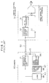
- Fig. 1 is a block diagram of the multiplex transmission system for multiplexing a video signal and power source to be transmitted.
- reference numeral 1 denotes a camera control device for taking out a video signal from a camera 40 located at a remote position and supplying power to the camera 40.
- Reference numeral 50 denotes a coaxial cable for connecting the camera control device 30 and the camera 40 with each other.
- the camera control device 30 includes an AC-DC converter 31 for converting a commercial power source into a DC power source to be used in the camera control device 30, and a constant current circuit 32 for regulating or stabilizing the output from the AC-DC converter 31.
- the camera 40 includes an impedance conversion unit 41 for converting a high impedance into a low impedance signal, and a constant voltage circuit unit 42 for regulating or stabilizing the voltage on the output side of the impedance conversion unit 41.
- the AC-DC converter converts a commercial AC power source into a DC power source which is used within the camera control device 30 and also sends the DC power source to the constant current circuit 32.
- the constant current circuit 32 regulates the sent power source to a constant current which is supplied to the camera 40 through the coaxial cable 50.
- the impedance conversion unit 41 converts the sent signal into a high impedance voltage source.
- the constant voltage unit 42 regulates the voltage source to a constant voltage which is supplied to load 43 within the camera 43.
- a video signal transmission circuit 44 in the camera 40 sends out a video signal to the coaxial cable 50 through a coupling capacitor 45.
- the video signal transmitted to the camera control device 30 through the coaxial cable 50 is transferred to a video signal output terminal 34 through a coupling capacitor 33.
- the video signal is sent out, in a base band as it is without being modulated, from the camera 40, and transmitted to the camera control device 30 through the coaxial cable 50.
- the power source regulated by the camera control device 30 is also transmitted as it is to the side of camera 40 through the coaxial cable 50.
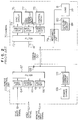
- Fig. 2 is a block diagram of a multiplex transmission system in which a video signal and plural signals other than the video signal are multiplexed to be transmitted.
- reference numeral 60 denotes a remote control unit
- reference numeral 70 denotes a camera connected with the remote control unit 60 through a coaxial cable 50.
- reference numerals 64, 66 and 74 denote modulators for modulating input signals at different predetermined frequencies
- reference numerals 65, 73 and 75 each denotes a demodulator for demodulating the modulated signal into the corresponding original signal
- reference numerals 67 and 72 each denotes a filter for removing or suppressing the harmonic at frequencies other than a predetermined frequency and extracting only a predetermined frequency from the signal transmitted through the coaxial cable 50
- reference numeral 59 denotes a constant current circuit for regulating or stabilizing a DC power source into a constant current
- reference 79 denotes an impedance conversion unit for converting a DC constant current source into the power with low impedance
- reference numeral 80 denotes a constant voltage circuit unit for regulating a DC power source to a stabilized constant voltage
- a sync input signal and a remote control signal applied to terminals 61 and 63 are modulated at predetermined frequencies f1 and f3 by the modulators 64 and 66, respectively; the modulated signals are applied to the filter 67.
- these multiplexed signals are transmitted to the side of the camera 70 through the coaxial cable 50, their frequency components of the frequencies f1 and f2 are extracted so that the resultant signals are applied to the demodulators 73 and 75.
- the original sync signal and remote control signal are demodulated by the demodulators 73 and 75 the outputs from which are sent to a sync circuit 76 and a control circuit 78.
- a video signal which is created by the side of the camera 70 is modulated at a predetermined frequency f2 by the modulator 74.
- the modulated signal is applied to the filter 72 and sent out to the coaxial cable 50 through a capacitor 71.
- the video signal transmitted to the side of the remote control unit 60 through the coaxial cable 50 is applied to the demodulator 65; the video signal demodulated into the original video signal is outputted from a terminal 62.
- the power source is applied from a power source unit 69 to the coaxial cable 50 through the constant current circuit 59. On the side of the camera, it is converted into the power with low impedance by the impedance conversion unit 79 and further stabilized to a constant voltage by the constant voltage circuit unit 80. The constant voltage is applied to a load 81.
- the video signal because its modulation and demodulation, may have S/N, a differential gain characteristic (referred to as DG characteristic) and differential phase characteristic (referred to as DP characteristic) which are deteriorated as compared with the video signal before the modulation; thus the video signal cannot be reproduced in its accurate original form.
- DG characteristic differential gain characteristic
- DP characteristic differential phase characteristic
- the present invention intends to solve the problems involved with the prior arts described above.
- An object of the present invention is to provide a multiplex transmission system and an apparatus therefor which can prevent a S/N, DG characteristic and DP characteristic from being deteriorated and other signals from plunging into the video period of a video signal.
- signals such as a remote control signal and a sync signal other than a video signal are modulated at the frequencies outside the band of the video signal, and the modulated signals are multiplexed for their transmission in such a way that they are multiplexed in synchronism with the blanking period of the video signal.
- a video signal can be transmitted in its base band, and hence the deterioration of the S/N, DG characteristic and DP characteristic during modulation/demodulation can be prevented.
- modulated signals are superposed on the blanking period of a video signal so that the signals other than the video signal will not plunge into the video period of the video signal and also the video signal will not be affected by e.g. beats.
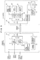
- Fig. 3 is a block diagram showing the arrangement of an embodiment of the present invention.
- reference numeral 1 denotes a remote control unit for manipulating or controlling a camera 13 from a remote position; the remote control unit 1 is connected with the camera 13 through a coaxial cable 12.
- the remote control unit 1 is provided with terminals 2, 3 and 4 for inputting/outputting a video output signal, a sync input signal and a remote control signal, respectively.
- reference numerals 5 and 6 denote modulators for modulating input signals at predetermined frequencies, respectively; reference numerals 17 and 18 denote demodulators for demodulating the modulated signals into the signals at predetermined frequencies; reference numeral 7 denotes a filter for passing only the predetermined frequency components of the modulated signals; reference numeral 16 denotes a filter for extracting only the predetermined frequency components of the signals transmitted through the coaxial cable 12; reference numeral 11 denotes a constant current circuit for stabilizing or regulating a DC power source into a constant current source; reference numeral 22 denotes an impedance conversion unit for converting a DC constant current source into the power with low impedance; reference numeral 23 denotes a constant voltage circuit unit for regulating a DC power source to a stabilized constant voltage; reference numeral 19 denotes a video signal sending-out circuit for amplifying a video signal obtained on the side of the camera to be sent out; reference numeral 20 denotes a sync circuit for producing
- a video signal obtained on the side of the camera will be transmitted as follows. It is amplified by the video signal sending-out circuit 19. The amplified video signal is sent out to the coaxial cable 12 thorough a coupling capacitor 14. The video signal is sent to the remote control unit 1 through the coaxial cable 12. The video signal will be transmitted as it is in its base band.
- the sync input signal and the remote control signal will be transmitted as follows.
- the sync input signal and the remote control input signal applied to the input terminals 3 and 4 are modulated at predetermined different frequencies f4 and f5 by the modulators 5 and 6, respectively.
- the modulated signals passed through the filter 7 are sent out to the coaxial cable 12 through a coupling capacitor 9.
- the signals are applied to the filter 16 through a coupling capacitor 15; thus the signals are separated into individual signals.
- the signals are demodulated into the corresponding original signals by the modulators 17 and 18.
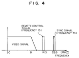
- Fig. 4 shows allotment of frequencies when the sync signal and the remote control signal are modulated.
- the video signal is located in its base band ranging from DC to 8 MHz.
- the sync signal is centered at 28. 6 MHz (frequency f4) and the remote control signal is centered at 14. 8 MHz (frequency f5). These frequencies are made sufficiently apart from one another in order to prevent interference among theses signals.
- the remote control input signal is modulated by the modulator 6 in synchronism with the sync pulses generated by the sync signal generating circuit 25 so that the modulated signal is adapted to be located during the vertical blanking period of the video signal.
- the modulated remote control signal is present within about 20 H (1H refers to 64 ⁇ sec) of the vertical blanking period (Fig. 5A). Namely, with respect to the modulated remote control signal (Fig.
- an AGC automatic gain control
- a digital control signal (4 word instruction, one word composed of 11 bits) which informs the camera of the states of the remote control unit and the several kinds of keys is located at 12-th H to 18-th H thereof.
- Fig. 5C shows the waveform of the modulated sync signal.
- Fig. 6 shows the waveform resulting when these video signal, modulated remote control signal and modulated sync signal are multiplexed.
- the power source will be transmitted as follows.
- a power source 10 on the side of the remote control unit 1 is applied to the coaxial cable 12 through the constant current circuit 11.
- the constant voltage is applied to the load 24.
- a video signal can be transmitted in its base band without being modulated and demodulated, and signals such as a sync signal and a remote control signal other than the video signal can also be modulated at different frequencies for their transmission.
- signals such as a sync signal and a remote control signal other than the video signal can also be modulated at different frequencies for their transmission.
- the video signal will not suffer from the deterioration of the S/N, DG characteristic and DP characteristic.
- the modulated remote control signal is superposed on the blanking period of the video signal so that the remote control signal will not plunge into the video period of the video signal and also the video signal will not be affected by e.g. beats.
- a video signal can be transmitted as it is in its base band, and hence the deterioration of the S/N, DG characteristic and DP characteristic during modulation/demodulation can be prevented.
- a modulated signal(s) is synchronous with the video signal to be superposed on the blanking period of the video signal so that the signals other than the video signal will not plunge into the video period of the video signal and also the video signal will not be affected by beats.
Landscapes
- Engineering & Computer Science (AREA)
- Multimedia (AREA)
- Signal Processing (AREA)
- Closed-Circuit Television Systems (AREA)
- Synchronizing For Television (AREA)
- Television Systems (AREA)
Applications Claiming Priority (2)
| Application Number | Priority Date | Filing Date | Title |
|---|---|---|---|
| JP3123653A JPH0583689A (ja) | 1991-05-28 | 1991-05-28 | 多重伝送方式およびその装置 |
| JP123653/91 | 1991-05-28 |
Publications (3)
| Publication Number | Publication Date |
|---|---|
| EP0516058A2 true EP0516058A2 (fr) | 1992-12-02 |
| EP0516058A3 EP0516058A3 (en) | 1993-06-09 |
| EP0516058B1 EP0516058B1 (fr) | 1996-09-18 |
Family
ID=14865943
Family Applications (1)
| Application Number | Title | Priority Date | Filing Date |
|---|---|---|---|
| EP92108870A Expired - Lifetime EP0516058B1 (fr) | 1991-05-28 | 1992-05-26 | Système de transmission multiplexé |
Country Status (3)
| Country | Link |
|---|---|
| EP (1) | EP0516058B1 (fr) |
| JP (1) | JPH0583689A (fr) |
| DE (1) | DE69213821T2 (fr) |
Cited By (5)
| Publication number | Priority date | Publication date | Assignee | Title |
|---|---|---|---|---|
| US5311311A (en) * | 1991-03-27 | 1994-05-10 | Sanyo Electric Co., Ltd. | Encoder for superimposing encoded character data or command data in the vertical blanking interval for regulating video receiver functions |
| DE19950531A1 (de) * | 1999-10-20 | 2001-05-10 | S. Siedle & Soehne,Telefon- Und Telegrafenwerke Stiftung & Co | Anlage für die Hauskommunikation |
| EP1781022A4 (fr) * | 2004-07-28 | 2008-01-23 | Matsushita Electric Industrial Co Ltd | Dispositif de camera de surveillance, procede de commande pour un dispositif de camera de surveillance et programme pour un dispositif de camera de surveillance |
| US8074089B2 (en) | 2007-11-08 | 2011-12-06 | Fujitsu Component Limited | Power supply controlling system |
| CN106713866A (zh) * | 2016-12-28 | 2017-05-24 | 浙江大华技术股份有限公司 | 一种模拟视频信号传输装置及其传输方法 |
Families Citing this family (3)
| Publication number | Priority date | Publication date | Assignee | Title |
|---|---|---|---|---|
| JP4478515B2 (ja) * | 2004-06-15 | 2010-06-09 | 株式会社日立国際電気 | 通信中継装置 |
| JP2009105710A (ja) * | 2007-10-24 | 2009-05-14 | Mitsubishi Electric Corp | 撮像装置 |
| WO2019207762A1 (fr) | 2018-04-27 | 2019-10-31 | オリンパス株式会社 | Système d'imagerie, et système d'endoscope |
Family Cites Families (5)
| Publication number | Priority date | Publication date | Assignee | Title |
|---|---|---|---|---|
| FR1557116A (fr) * | 1967-12-27 | 1969-02-14 | ||
| FR1598256A (fr) * | 1968-12-03 | 1970-07-06 | ||
| JPS55130275A (en) * | 1979-03-30 | 1980-10-08 | Toshiba Corp | Television camera device |
| DE3750809T2 (de) * | 1986-12-19 | 1995-06-01 | Sharp Kk | Multiplexübertragungssystem mit überlagerter Gleichstromversorgung und einem einzigen parallelen Kabel. |
| JP2651872B2 (ja) * | 1989-09-28 | 1997-09-10 | 松下電器産業株式会社 | Cctvシステム装置 |
-
1991
- 1991-05-28 JP JP3123653A patent/JPH0583689A/ja active Pending
-
1992
- 1992-05-26 EP EP92108870A patent/EP0516058B1/fr not_active Expired - Lifetime
- 1992-05-26 DE DE69213821T patent/DE69213821T2/de not_active Expired - Fee Related
Cited By (6)
| Publication number | Priority date | Publication date | Assignee | Title |
|---|---|---|---|---|
| US5311311A (en) * | 1991-03-27 | 1994-05-10 | Sanyo Electric Co., Ltd. | Encoder for superimposing encoded character data or command data in the vertical blanking interval for regulating video receiver functions |
| DE19950531A1 (de) * | 1999-10-20 | 2001-05-10 | S. Siedle & Soehne,Telefon- Und Telegrafenwerke Stiftung & Co | Anlage für die Hauskommunikation |
| EP1781022A4 (fr) * | 2004-07-28 | 2008-01-23 | Matsushita Electric Industrial Co Ltd | Dispositif de camera de surveillance, procede de commande pour un dispositif de camera de surveillance et programme pour un dispositif de camera de surveillance |
| US7532237B2 (en) | 2004-07-28 | 2009-05-12 | Panasonic Corporation | Monitor camera device, control method for monitor camera device, and program for monitor camera device |
| US8074089B2 (en) | 2007-11-08 | 2011-12-06 | Fujitsu Component Limited | Power supply controlling system |
| CN106713866A (zh) * | 2016-12-28 | 2017-05-24 | 浙江大华技术股份有限公司 | 一种模拟视频信号传输装置及其传输方法 |
Also Published As
| Publication number | Publication date |
|---|---|
| DE69213821T2 (de) | 1997-03-13 |
| DE69213821D1 (de) | 1996-10-24 |
| EP0516058A3 (en) | 1993-06-09 |
| EP0516058B1 (fr) | 1996-09-18 |
| JPH0583689A (ja) | 1993-04-02 |
Similar Documents
| Publication | Publication Date | Title |
|---|---|---|
| KR100343764B1 (ko) | 색차신호 변환회로 | |
| EP0516058B1 (fr) | Système de transmission multiplexé | |
| EP0781050A2 (fr) | Système de transmission optique pour signaux | |
| US4318131A (en) | TV Camera system having synchronized oscillators in camera head and CCU | |
| JP4082474B2 (ja) | 回転台システム | |
| EP0515064B1 (fr) | Circuit de commande de la transmission d'information pour une caméra de télévision de surveillance | |
| JPS6192084A (ja) | デ−タ伝送方式 | |
| JPH10191148A (ja) | ケーブル補償装置 | |
| KR100212384B1 (ko) | 비디오 신호 전송 방법 | |
| JP2767912B2 (ja) | 信号伝送装置 | |
| US4185295A (en) | Method of mixing SECAM color-T.V. signals | |
| CA2054859C (fr) | Convertisseur abaisseur pour systeme de communication a satellite | |
| GB2105150A (en) | Television systems | |
| US3145262A (en) | Television system for producing superimposed images | |
| JP2819909B2 (ja) | テレビカメラ用信号伝送システム | |
| EP0416367A2 (fr) | Dispositif de traitement du signal couleur SECAM | |
| JPS633275Y2 (fr) | ||
| JPS5821987A (ja) | 映像信号伝送処理方式 | |
| KR900005187B1 (ko) | 수직윤곽 보정장치 | |
| JP3496621B2 (ja) | Fpuカメラの同期システム | |
| JPH0414915B2 (fr) | ||
| JPS6230495A (ja) | デジタル化ビデオ信号の伝送方法 | |
| JPH07101932B2 (ja) | 高精細化テレビジョン信号用agc回路 | |
| EP0431875A2 (fr) | Dispositif d'addition d'un signal de dispersion d'énergie et dispositif pour supprimer ce signal | |
| JPS6267974A (ja) | テレビジヨンカメラの制御信号伝送方式 |
Legal Events
| Date | Code | Title | Description |
|---|---|---|---|
| PUAI | Public reference made under article 153(3) epc to a published international application that has entered the european phase |
Free format text: ORIGINAL CODE: 0009012 |
|
| AK | Designated contracting states |
Kind code of ref document: A2 Designated state(s): DE FR GB |
|
| PUAL | Search report despatched |
Free format text: ORIGINAL CODE: 0009013 |
|
| AK | Designated contracting states |
Kind code of ref document: A3 Designated state(s): DE FR GB |
|
| 17P | Request for examination filed |
Effective date: 19930707 |
|
| 17Q | First examination report despatched |
Effective date: 19950801 |
|
| GRAG | Despatch of communication of intention to grant |
Free format text: ORIGINAL CODE: EPIDOS AGRA |
|
| GRAH | Despatch of communication of intention to grant a patent |
Free format text: ORIGINAL CODE: EPIDOS IGRA |
|
| GRAH | Despatch of communication of intention to grant a patent |
Free format text: ORIGINAL CODE: EPIDOS IGRA |
|
| GRAA | (expected) grant |
Free format text: ORIGINAL CODE: 0009210 |
|
| AK | Designated contracting states |
Kind code of ref document: B1 Designated state(s): DE FR GB |
|
| REF | Corresponds to: |
Ref document number: 69213821 Country of ref document: DE Date of ref document: 19961024 |
|
| ET | Fr: translation filed | ||
| PLBE | No opposition filed within time limit |
Free format text: ORIGINAL CODE: 0009261 |
|
| STAA | Information on the status of an ep patent application or granted ep patent |
Free format text: STATUS: NO OPPOSITION FILED WITHIN TIME LIMIT |
|
| 26N | No opposition filed | ||
| REG | Reference to a national code |
Ref country code: GB Ref legal event code: IF02 |
|
| PGFP | Annual fee paid to national office [announced via postgrant information from national office to epo] |
Ref country code: FR Payment date: 20060515 Year of fee payment: 15 |
|
| PGFP | Annual fee paid to national office [announced via postgrant information from national office to epo] |
Ref country code: DE Payment date: 20060518 Year of fee payment: 15 |
|
| PGFP | Annual fee paid to national office [announced via postgrant information from national office to epo] |
Ref country code: GB Payment date: 20060524 Year of fee payment: 15 |
|
| GBPC | Gb: european patent ceased through non-payment of renewal fee |
Effective date: 20070526 |
|
| REG | Reference to a national code |
Ref country code: FR Ref legal event code: ST Effective date: 20080131 |
|
| PG25 | Lapsed in a contracting state [announced via postgrant information from national office to epo] |
Ref country code: DE Free format text: LAPSE BECAUSE OF NON-PAYMENT OF DUE FEES Effective date: 20071201 |
|
| PG25 | Lapsed in a contracting state [announced via postgrant information from national office to epo] |
Ref country code: GB Free format text: LAPSE BECAUSE OF NON-PAYMENT OF DUE FEES Effective date: 20070526 |
|
| PG25 | Lapsed in a contracting state [announced via postgrant information from national office to epo] |
Ref country code: FR Free format text: LAPSE BECAUSE OF NON-PAYMENT OF DUE FEES Effective date: 20070531 |