EP0516446A2 - Disjoncteur dans lequel un soudage des contacts bloque le levier - Google Patents
Disjoncteur dans lequel un soudage des contacts bloque le levier Download PDFInfo
- Publication number
- EP0516446A2 EP0516446A2 EP92304906A EP92304906A EP0516446A2 EP 0516446 A2 EP0516446 A2 EP 0516446A2 EP 92304906 A EP92304906 A EP 92304906A EP 92304906 A EP92304906 A EP 92304906A EP 0516446 A2 EP0516446 A2 EP 0516446A2
- Authority
- EP
- European Patent Office
- Prior art keywords
- movable contact
- handle
- bar
- cross
- circuit breaker
- Prior art date
- Legal status (The legal status is an assumption and is not a legal conclusion. Google has not performed a legal analysis and makes no representation as to the accuracy of the status listed.)
- Granted
Links
Images


Classifications
-
- H—ELECTRICITY
- H01—ELECTRIC ELEMENTS
- H01H—ELECTRIC SWITCHES; RELAYS; SELECTORS; EMERGENCY PROTECTIVE DEVICES
- H01H71/00—Details of the protective switches or relays covered by groups H01H73/00 - H01H83/00
- H01H71/10—Operating or release mechanisms
- H01H71/50—Manual reset mechanisms which may be also used for manual release
- H01H71/501—Means for breaking welded contacts; Indicating contact welding or other malfunction of the circuit breaker
- H01H2071/502—Means for breaking welded contacts; Indicating contact welding or other malfunction of the circuit breaker with direct contact between manual operator and welded contact structure
-
- Y—GENERAL TAGGING OF NEW TECHNOLOGICAL DEVELOPMENTS; GENERAL TAGGING OF CROSS-SECTIONAL TECHNOLOGIES SPANNING OVER SEVERAL SECTIONS OF THE IPC; TECHNICAL SUBJECTS COVERED BY FORMER USPC CROSS-REFERENCE ART COLLECTIONS [XRACs] AND DIGESTS
- Y10—TECHNICAL SUBJECTS COVERED BY FORMER USPC
- Y10S—TECHNICAL SUBJECTS COVERED BY FORMER USPC CROSS-REFERENCE ART COLLECTIONS [XRACs] AND DIGESTS
- Y10S200/00—Electricity: circuit makers and breakers
- Y10S200/42—Contact welding considerations
Definitions
- This invention relates to a circuit breaker in which the handle is blocked from movement to the off position when the contacts are welded closed.
- a common type of circuit breaker has a fixed electrical contact, and a movable electrical contact mounted on a movable contact arm. The contacts are closed and opened by rotating a handle between an on and off position, respectively.
- a latchable cradle connected to the movable contact arm by a spring operated toggle device is held in a latched position by a trip device.
- the trip mechanism unlatches the latchable cradle and the spring operated toggle device rotates the movable contact arm to open the contacts.
- the spring operated toggle device also moves the handle to a trip position intermediate the on and off positions.
- the handle provides a visual indication of the state of the circuit breaker.
- the circuit breaker is reset by moving the handle slightly past the off position to relatch the latchable cradle, and then to the on position to reclose the contacts.
- the trip device of the circuit breaker described above can respond to the overload condition by unlatching the latchable cradle. If the weld is of sufficient strength, the contact arm cannot be rotated and the contacts remain closed. However, it is possible to rotate the handle to the off position to relatch the cradle.
- a blocking member on the movable contact arm structure prevents the cradle from moving to a position at which it can be relatched by the trip mechanism when the handle is moved to the off position following a trip with the contacts welded closed.
- a latch on the cradle engages a stationary part to prevent rotation of the cradle to the relatched position following a trip with the contacts welded closed.
- the springs bias the handle to the on position under these conditions to indicate the real position of the welded contacts.
- a handle yoke latch prevents rotation of the handle to the reset position if the contacts are welded closed.
- the movable contact arm structure rotates the handle yoke latch out of the path of the handle yoke to permit a tripped circuit breaker to be reset.
- circuit breakers are operated remotely by a motor operator. If the handle can be moved to the off position even though biased to the on position, the motor operator could hold the handle in the off position providing an indication that the contacts of the circuit breaker were open when in fact they were welded closed.
- the circuit breaker is mounted in a cabinet with the handle mechanism extending through the cabinet door wall for external operation.
- a handle mechanism it is possible for such a handle mechanism to have sufficient friction that the handle could remain in the off position despite the spring bias in the circuit breaker to the open position when the contacts were welded closed.
- a hasp lock is provided to lock the circuit breaker in the off position. If the handle can be moved to the off position with the contacts welded closed, it is possible for the handle to be locked in the off position when in fact the contacts are welded closed. Obviously, this is not a satisfactory condition.
- U.S. Patent No. 3,849,747 discloses a miniature circuit breaker with a latchable cradle which is connected by a spring to a movable contact arm which in turn is connected to a handle. Since the handle is connected directly to the contact arm, it cannot be moved to the off position if the contacts are welded closed, and correspondingly, the handle cannot be relatched.
- An object of the present invention is to provide a circuit breaker with an improved arrangement for preventing movement of the operating handle to the off position when the contacts are welded closed.
- an electrical circuit breaker comprises a fixed contact, a movable contact, a movable contact arm structure carrying said movable contact and rotatable between open and closed positions to open and close said contacts, a spring powered operating mechanism including a pivoted operating member carrying a handle, said operating mechanism connected to said movable contact arm structure for rotating said movable contact arm structure between an on position of said handle in which said movable contact arm structure is in the closed position to close said contacts and an off position of said handle in which said movable contact arm structure is in the off position to open said contacts, a trip device responsive to predetermined current overload conditions in the circuit breaker to actuate said spring powered operating mechanism to rotate the movable contact arm structure to the open position and to place the handle in a trip position between said on and off positions, said trip device being reset by moving said handle past the off position, and interlock means comprising a radially extending projection on said movable contact arm structure having a generally radially outward facing abutment surface, and a
- a trip device actuates the spring powered operating mechanism to rotate the movable contact arm structure to the open position and place the handle in a tripped position between the on and off positions in response to predetermined current overload conditions.
- the circuit breaker is provided with an interlock which includes a radially extending projection on the movable contact arm structure having a generally radially outward facing abutment surface, and a generally radially facing engagement surface on the pivoted operating member.
- the engagement surface on the pivoted operating member engages the abutment surface on the movable contact arm structure to prevent movement of the handle to the off position when the movable contact arm structure is prevented from rotating with the contacts welded closed.
- the movable contact arm structure includes a cross-bar mounted for rotation about a longitudinal axis and on which are mounted contact arms carrying the movable contacts.
- the projection forming part of the interlock extends radially outward from the cross-bar.
- This projection may be integrally molded with the molded cross-bar or may take the form of an insert seated in a recess in the cross-bar.
- the pivoted operating member includes a handle yoke having a pair of arms pivoted for movement about free ends, and the engagement surface is provided on extensions on the yoke arms.
- a pair of projections are provided on the cross-bar with each projection aligned with one of the extensions on the handle yoke.
- the abutment surfaces on the projections are curved about a center which is coaxial with the longitudinal axis of the cross-bar. With the curved abutment surface, rotation of the handle is arrested at a fixed position despite relative rotation between the contact arm of a welded contact and a cross-bar due to contact loading springs in the cross-bar.
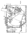
- Figure 1 is a plan view of a circuit breaker.
- Figure 2 is a longitudinal vertical section taken along the line II-II of the circuit breaker of Figure 1 shown in the on or closed position with some parts broken away.
- Figure 3 is a transverse vertical section of the circuit breaker of Figure 2 taken along the line III-III.
- Figure 4 is a fragmentary view similar to the view of Figure 2 showing the circuit breaker in the reset position which is slightly past the normal open or off position.
- Figure 5 is a fragmentary view similar to Figure 2 showing the circuit breaker in the normal trip position.
- Figure 6 is an enlargement of a portion of the vertical section shown in Figure 2.
- Figure 7 is a fragmentary view similar to Figure 2 showing the circuit breaker when an attempt is made to move the handle to the off position with the contacts welded closed.
- Figure 1 shows the circuit breaker 1 including a molded, electrically insulating enclosure 3 comprising a base 5 (see Figure 2) and a removable cover 7.
- a set of input terminals 9a, 9b and 9c, one for each pole, and a set of output terminals 11a, 11b and 11c, are provided to connect the circuit breaker 1 into, in this instance, a three phase electrical system to be protected by the circuit breaker.
- a handle 13 for manually opening and closing the circuit breaker, and for indicating the state of circuit breaker extends through an opening 15 in the cover 7.
- circuit breaker 1 includes for each pole a lower contact structure 17, a movable contact structure 19, an arc chute 21 to aid in extinguishing the electrical arc created by the interrupting current through the pole, and a slot motor 23 to aid in accelerating interruption of the current.
- the major components of the circuit breaker 1 also include a common latchable cradle 25, a spring operated actuating mechanism 27, an operating member 29 and a trip mechanism 31 which is responsive to predetermined overcurrent conditions in each pole.
- the lower contact structure 17 includes a stationary conducting member 33, the outer end of which constitutes the input terminal 9 for the respective pole.
- the stationary conducting member 33 has a cantilevered inner end 35 which carries a fixed electrical contact 37.
- the movable contact structure 19 includes a movable contact arm 39 carrying at its outer end a movable electrical contact 41.
- Each of the movable contact arms 39 is mounted on a common transverse cross-bar 43 for simultaneous rotational movement between a closed position shown in Figure 2 and an open position shown in Figure 4.
- the fixed electrical contact 37 and the movable electrical contact 41 form a set of contacts 45 which are closed to complete an electrical circuit through the circuit breaker when the contact arm is in the closed position, and to interrupt current through the respective pole of the circuit breaker when the contact arm is in the open position.
- a flexible conductor 47 is connected between the movable contact arm 39 and a bimetal 49 which in turn is connected to the respective output terminal 11.
- the movable contact arms 39 for the three poles are pivotally connected to the common cross-bar 43 and are biased by compression springs 51 mounted in recesses within the cross-bar. These compression springs 51 insure that the movable contact arms 39 move in unison with the cross-bar 43 and apply a predetermined closing force to the set of contacts 45. They also permit the electrical contacts 45 to rapidly separate when blown open by a high level short circuit without waiting for the operating mechanism to sequence.
- the common cross-bar 43 is journalled for rotation in apertures 53 in spaced apart side plates 55 secured in partitions 57 in the molded base 5 of the circuit breaker. Axial movement of the cross-bar is restrained by integral flanges 59 which are engaged by grooves 61 in the partitions 57. Insulating panels 63 electrically isolate the poles of the circuit breaker 1.
- the latchable cradle 25 is mounted for rotation about one end by a cradle pin 65 supported by the side plates 55.
- the free end of the latchable cradle includes a slot or groove defining a latching surface 67. This latching surface 67 engages a slot 69 in a latch plate 71 which forms part of the trip mechanism 31.
- the operating member 29 includes a U-shaped yoke 73 having a pair of spaced apart parallel arms 75 (shown broken partly away in Figure 2) joined by a web 77. As is best seen in Figure 3, arcuate free ends of tabs 79 inwardly offset from the lower ends of the operating member arms 75 are received in and rotate in arcuate recesses 81 in the side plates 55.
- the operating member 29 includes the handle 13 having an integrally molded base 83 which is secured to the yoke 73.
- the handle 13, and with it the yoke 73, are movable between the on position shown in Figure 2 and a reset position shown in Figure 4 which is slightly past the off position. They are also positionable to a trip position shown in Figure 5 which is intermediate the on and off positions.
- the cradle 25 includes a yoke contacting surface 85 configured to contact a flange 87 on the web 77 through a slot 89 in the molded base 83 on the handle 13. (See Figures 2 and 3.)
- the contact surface 85 on the cradle 25 contacts the flange 87 to position the handle to the tripped position when the trip mechanism releases the cradle.
- the flange 87 contacts the surface 85 to rotate the cradle 25 for relatching.
- the spring operated actuating mechanism 27 includes a toggle device 91 and a pair of helical tension springs 93.
- the toggle device 91 includes a pair of lower toggle arms 95 straddling the movable contact arm 39 of the center pole and pivotally connected thereto by a lower toggle pin 97.
- the toggle device 91 further includes a pair of upper toggle arms 99 straddling the latchable cradle 25 and having an upper toggle pin 103 extending through and connected to the cradle 25.
- the upper and lower pairs of toggle arms 99 and 95 are pivotally connected together by a toggle knee pin 105.
- the pair of helical tension springs 93 are stretched between the web 77 of the yoke 73 and the toggle knee pin 105 outside the upper toggle arms 99.
- the trip device 31 Upon the occurrence of predetermined overcurrent conditions in one of the poles of the circuit breaker 1, the trip device 31 (such as described in the specification of U.S. patent no. 4,630,019) is operated to rotate the latching plate 71 out of engagement with the latching surface 67 on the latchable cradle 25. With the cradle 25 unlatched, the springs 93 acting through the toggle knee pin 105, upper toggle arms 99 and upper toggle pin 103, rapidly accelerate the latchable cradle 25 in the counterclockwise direction as viewed in Figure 2. This shifts the line of action of the tension springs 93 behind the toggle pin 103 causing the toggle mechanism to collapse, thereby raising the toggle knee pin 105, and through the lower toggle arms 95, the lower toggle pin 97.
- the handle 13 To reset the circuit breaker the handle 13 is moved toward, and slightly past the off, or full clockwise position, as viewed in Figure 4. As the handle is brought to this reset position, the flange 87 on the yoke 73 bears against the surface 85 on the latchable cradle 25 to rotate the cradle clockwise until the latching surface 67 engages the intermediate latch plate 71 of the trip mechanism 31. Movement of the handle to this position causes the line of action of the springs 93 to move to the right of the toggle pin 103 so that the handle remains in the off position.
- An interlock 107 is provided to prevent rotation of the handle 13 to the off position when the contacts 45 are welded closed.
- the interlock 107 includes longitudinal extensions 109 on the arms 75 of the yoke 73.
- the extensions 109 extend in the plane of the arm 75 and are thus outside of the side plates 55 as can be seen in Figure 3. These extensions 109 terminate in radial engagement surfaces 111.
- the interlock 107 also includes radially outwardly by extending projections 113 on the cross-bar 43. These projections 113 can be integrally molded with the cross-bar 43.
- radial recesses 115 are molded in the cross-bar 43, and the projections 113 are formed by inserts 117 seated in the recesses 115.
- the inserts 117 can be made from a different material than the resin of the molded cross-bar 43.
- the inserts 117 can be made of metal for metal-to-metal contact with the extensions 109 on the yoke 73.
- the projections 113 such as the inserts 117 terminate in radially outward facing abutment surfaces 119. These surfaces 119 form a sector of a circle of radius r centered on the longitudinal axis 121 of the cross-bar 43.
- the projections 113 are axially aligned on the cross-bar 43 to be in the same plane as the extensions 109 on the arms 75 of the yoke 73.
- the cross-bar is positioned so that the projections 113 extend upward toward the extensions 109 on the yoke arms 75.
- the yoke 73 is rotated so that there is clearance between the extensions 109 and the projection 113 on the cross-bar.
- the toggle device 91 operates as previously explained to rotate the contact arms 39 and the cross-bar 43 to the position shown in Figure 5 wherein the cross-bar has been rotated clockwise out of the way of the extension 109 on the yoke arm 75. If the handle is then moved rearwardly toward the off position to reset the circuit breaker, or the handle is moved manually to the off position to open the circuit breaker, the yoke 73 is free to rotate to the off position since the projections 113 have been rotated out of the way of the extensions 109 on the yoke 73.
- the compression springs 51 allow the cross-bar to rotate a few degrees.
- the abutment surfaces 119 of the projections 113 are arcuate surfaces having a center of curvature centered on the longitudinal axis 121 of the cross-bar, the allowable over-travel of the handle remains at three degrees over center.
Landscapes
- Breakers (AREA)
- Connections Effected By Soldering, Adhesion, Or Permanent Deformation (AREA)
Applications Claiming Priority (2)
| Application Number | Priority Date | Filing Date | Title |
|---|---|---|---|
| US706714 | 1991-05-29 | ||
| US07/706,714 US5184717A (en) | 1991-05-29 | 1991-05-29 | Circuit breaker with welded contacts |
Publications (3)
| Publication Number | Publication Date |
|---|---|
| EP0516446A2 true EP0516446A2 (fr) | 1992-12-02 |
| EP0516446A3 EP0516446A3 (en) | 1993-05-05 |
| EP0516446B1 EP0516446B1 (fr) | 1998-03-11 |
Family
ID=24838756
Family Applications (1)
| Application Number | Title | Priority Date | Filing Date |
|---|---|---|---|
| EP92304906A Expired - Lifetime EP0516446B1 (fr) | 1991-05-29 | 1992-05-29 | Disjoncteur dans lequel un soudage des contacts bloque le levier |
Country Status (8)
| Country | Link |
|---|---|
| US (1) | US5184717A (fr) |
| EP (1) | EP0516446B1 (fr) |
| JP (1) | JPH05182577A (fr) |
| AT (1) | ATE164028T1 (fr) |
| AU (1) | AU652821B2 (fr) |
| CA (1) | CA2069796C (fr) |
| DE (1) | DE69224681T2 (fr) |
| NZ (1) | NZ242511A (fr) |
Cited By (4)
| Publication number | Priority date | Publication date | Assignee | Title |
|---|---|---|---|---|
| GB2286290A (en) * | 1994-02-03 | 1995-08-09 | Kloeckner Moeller Gmbh | Circuit breaker with blocking mechanism |
| EP0945883A3 (fr) * | 1998-03-23 | 2000-05-31 | Eaton Corporation | Disjoncteur avec anti-soulèvement pour une poignée pivotante |
| EP1515351A3 (fr) * | 2003-09-10 | 2007-05-02 | General Electric Company | Verroillage pour levier d'un disjoncteur |
| CN103681137A (zh) * | 2013-12-25 | 2014-03-26 | 大全集团有限公司 | 一种具有隔离功能的塑壳断路器 |
Families Citing this family (92)
| Publication number | Priority date | Publication date | Assignee | Title |
|---|---|---|---|---|
| IT1292453B1 (it) | 1997-07-02 | 1999-02-08 | Aeg Niederspannungstech Gmbh | Gruppo rotante di contatti per interrutttori di alta portata |
| DE19819242B4 (de) | 1998-04-29 | 2005-11-10 | Ge Power Controls Polska Sp.Z.O.O. | Thermomagnetischer Leistungsschalter |
| US6114641A (en) | 1998-05-29 | 2000-09-05 | General Electric Company | Rotary contact assembly for high ampere-rated circuit breakers |
| US6087913A (en) | 1998-11-20 | 2000-07-11 | General Electric Company | Circuit breaker mechanism for a rotary contact system |
| US6037555A (en) | 1999-01-05 | 2000-03-14 | General Electric Company | Rotary contact circuit breaker venting arrangement including current transformer |
| US6166344A (en) | 1999-03-23 | 2000-12-26 | General Electric Company | Circuit breaker handle block |
| US6262872B1 (en) | 1999-06-03 | 2001-07-17 | General Electric Company | Electronic trip unit with user-adjustable sensitivity to current spikes |
| US6268991B1 (en) | 1999-06-25 | 2001-07-31 | General Electric Company | Method and arrangement for customizing electronic circuit interrupters |
| US6218917B1 (en) | 1999-07-02 | 2001-04-17 | General Electric Company | Method and arrangement for calibration of circuit breaker thermal trip unit |
| US6188036B1 (en) | 1999-08-03 | 2001-02-13 | General Electric Company | Bottom vented circuit breaker capable of top down assembly onto equipment |
| US6710988B1 (en) | 1999-08-17 | 2004-03-23 | General Electric Company | Small-sized industrial rated electric motor starter switch unit |
| US6252365B1 (en) | 1999-08-17 | 2001-06-26 | General Electric Company | Breaker/starter with auto-configurable trip unit |
| US6175288B1 (en) | 1999-08-27 | 2001-01-16 | General Electric Company | Supplemental trip unit for rotary circuit interrupters |
| US6396369B1 (en) | 1999-08-27 | 2002-05-28 | General Electric Company | Rotary contact assembly for high ampere-rated circuit breakers |
| US6232570B1 (en) | 1999-09-16 | 2001-05-15 | General Electric Company | Arcing contact arrangement |
| US6326869B1 (en) | 1999-09-23 | 2001-12-04 | General Electric Company | Clapper armature system for a circuit breaker |
| US6239395B1 (en) | 1999-10-14 | 2001-05-29 | General Electric Company | Auxiliary position switch assembly for a circuit breaker |
| US6229413B1 (en) | 1999-10-19 | 2001-05-08 | General Electric Company | Support of stationary conductors for a circuit breaker |
| US6317018B1 (en) | 1999-10-26 | 2001-11-13 | General Electric Company | Circuit breaker mechanism |
| US6232856B1 (en) | 1999-11-02 | 2001-05-15 | General Electric Company | Magnetic shunt assembly |
| US6377144B1 (en) | 1999-11-03 | 2002-04-23 | General Electric Company | Molded case circuit breaker base and mid-cover assembly |
| ES2249875T3 (es) | 1999-11-03 | 2006-04-01 | AEG NIEDERSPANNUNGSTECHNIK GMBH & CO. KG | Disposicion de brazo de contacto rotatorio para disyuntor. |
| US6300586B1 (en) | 1999-12-09 | 2001-10-09 | General Electric Company | Arc runner retaining feature |
| US6310307B1 (en) | 1999-12-17 | 2001-10-30 | General Electric Company | Circuit breaker rotary contact arm arrangement |
| US6172584B1 (en) | 1999-12-20 | 2001-01-09 | General Electric Company | Circuit breaker accessory reset system |
| US6184761B1 (en) | 1999-12-20 | 2001-02-06 | General Electric Company | Circuit breaker rotary contact arrangement |
| US6215379B1 (en) | 1999-12-23 | 2001-04-10 | General Electric Company | Shunt for indirectly heated bimetallic strip |
| US6281461B1 (en) | 1999-12-27 | 2001-08-28 | General Electric Company | Circuit breaker rotor assembly having arc prevention structure |
| JP3857139B2 (ja) * | 1999-12-28 | 2006-12-13 | 三菱電機株式会社 | 回路遮断器 |
| US6346869B1 (en) | 1999-12-28 | 2002-02-12 | General Electric Company | Rating plug for circuit breakers |
| US6211758B1 (en) | 2000-01-11 | 2001-04-03 | General Electric Company | Circuit breaker accessory gap control mechanism |
| US6239677B1 (en) | 2000-02-10 | 2001-05-29 | General Electric Company | Circuit breaker thermal magnetic trip unit |
| US6429759B1 (en) | 2000-02-14 | 2002-08-06 | General Electric Company | Split and angled contacts |
| US6222143B1 (en) * | 2000-02-18 | 2001-04-24 | Siemens Energy & Automation, Inc. | Positive off toggle mechanism |
| US6281458B1 (en) | 2000-02-24 | 2001-08-28 | General Electric Company | Circuit breaker auxiliary magnetic trip unit with pressure sensitive release |
| US6313425B1 (en) | 2000-02-24 | 2001-11-06 | General Electric Company | Cassette assembly with rejection features |
| US6404314B1 (en) | 2000-02-29 | 2002-06-11 | General Electric Company | Adjustable trip solenoid |
| US6204743B1 (en) | 2000-02-29 | 2001-03-20 | General Electric Company | Dual connector strap for a rotary contact circuit breaker |
| US6346868B1 (en) | 2000-03-01 | 2002-02-12 | General Electric Company | Circuit interrupter operating mechanism |
| US6379196B1 (en) | 2000-03-01 | 2002-04-30 | General Electric Company | Terminal connector for a circuit breaker |
| US6340925B1 (en) | 2000-03-01 | 2002-01-22 | General Electric Company | Circuit breaker mechanism tripping cam |
| US6448521B1 (en) | 2000-03-01 | 2002-09-10 | General Electric Company | Blocking apparatus for circuit breaker contact structure |
| US6366438B1 (en) | 2000-03-06 | 2002-04-02 | General Electric Company | Circuit interrupter rotary contact arm |
| US6211757B1 (en) | 2000-03-06 | 2001-04-03 | General Electric Company | Fast acting high force trip actuator |
| US6459349B1 (en) | 2000-03-06 | 2002-10-01 | General Electric Company | Circuit breaker comprising a current transformer with a partial air gap |
| US6496347B1 (en) | 2000-03-08 | 2002-12-17 | General Electric Company | System and method for optimization of a circuit breaker mechanism |
| US6429659B1 (en) | 2000-03-09 | 2002-08-06 | General Electric Company | Connection tester for an electronic trip unit |
| US6218919B1 (en) | 2000-03-15 | 2001-04-17 | General Electric Company | Circuit breaker latch mechanism with decreased trip time |
| US6366188B1 (en) | 2000-03-15 | 2002-04-02 | General Electric Company | Accessory and recess identification system for circuit breakers |
| US6232859B1 (en) | 2000-03-15 | 2001-05-15 | General Electric Company | Auxiliary switch mounting configuration for use in a molded case circuit breaker |
| US6421217B1 (en) | 2000-03-16 | 2002-07-16 | General Electric Company | Circuit breaker accessory reset system |
| US6459059B1 (en) | 2000-03-16 | 2002-10-01 | General Electric Company | Return spring for a circuit interrupter operating mechanism |
| US6472620B2 (en) | 2000-03-17 | 2002-10-29 | Ge Power Controls France Sas | Locking arrangement for circuit breaker draw-out mechanism |
| US6559743B2 (en) | 2000-03-17 | 2003-05-06 | General Electric Company | Stored energy system for breaker operating mechanism |
| US6388213B1 (en) | 2000-03-17 | 2002-05-14 | General Electric Company | Locking device for molded case circuit breakers |
| US6639168B1 (en) | 2000-03-17 | 2003-10-28 | General Electric Company | Energy absorbing contact arm stop |
| US6586693B2 (en) | 2000-03-17 | 2003-07-01 | General Electric Company | Self compensating latch arrangement |
| US6476698B1 (en) | 2000-03-17 | 2002-11-05 | General Electric Company | Convertible locking arrangement on breakers |
| US6373010B1 (en) | 2000-03-17 | 2002-04-16 | General Electric Company | Adjustable energy storage mechanism for a circuit breaker motor operator |
| FR2806548B1 (fr) | 2000-03-17 | 2002-08-23 | Ge Power Controls France | Mecanisme extractible pour disjoncteurs |
| US6479774B1 (en) | 2000-03-17 | 2002-11-12 | General Electric Company | High energy closing mechanism for circuit breakers |
| US6747535B2 (en) | 2000-03-27 | 2004-06-08 | General Electric Company | Precision location system between actuator accessory and mechanism |
| US6373357B1 (en) | 2000-05-16 | 2002-04-16 | General Electric Company | Pressure sensitive trip mechanism for a rotary breaker |
| JP3859053B2 (ja) * | 2000-07-07 | 2006-12-20 | 富士電機機器制御株式会社 | 回路遮断器 |
| US6400245B1 (en) | 2000-10-13 | 2002-06-04 | General Electric Company | Draw out interlock for circuit breakers |
| US6806800B1 (en) | 2000-10-19 | 2004-10-19 | General Electric Company | Assembly for mounting a motor operator on a circuit breaker |
| US6531941B1 (en) | 2000-10-19 | 2003-03-11 | General Electric Company | Clip for a conductor in a rotary breaker |
| US6429760B1 (en) | 2000-10-19 | 2002-08-06 | General Electric Company | Cross bar for a conductor in a rotary breaker |
| US6362711B1 (en) | 2000-11-10 | 2002-03-26 | General Electric Company | Circuit breaker cover with screw locating feature |
| US6380829B1 (en) | 2000-11-21 | 2002-04-30 | General Electric Company | Motor operator interlock and method for circuit breakers |
| US6448522B1 (en) | 2001-01-30 | 2002-09-10 | General Electric Company | Compact high speed motor operator for a circuit breaker |
| US6476337B2 (en) | 2001-02-26 | 2002-11-05 | General Electric Company | Auxiliary switch actuation arrangement |
| US6882258B2 (en) * | 2001-02-27 | 2005-04-19 | General Electric Company | Mechanical bell alarm assembly for a circuit breaker |
| US6678135B2 (en) * | 2001-09-12 | 2004-01-13 | General Electric Company | Module plug for an electronic trip unit |
| US6469882B1 (en) | 2001-10-31 | 2002-10-22 | General Electric Company | Current transformer initial condition correction |
| US6804101B2 (en) | 2001-11-06 | 2004-10-12 | General Electric Company | Digital rating plug for electronic trip unit in circuit breakers |
| JP3972782B2 (ja) * | 2002-09-26 | 2007-09-05 | 富士電機機器制御株式会社 | 回路しゃ断器 |
| JP4059058B2 (ja) | 2002-10-28 | 2008-03-12 | 富士電機機器制御株式会社 | 回路しゃ断器 |
| US6714108B1 (en) | 2003-04-02 | 2004-03-30 | Eaton Corporation | Circuit breaker including mechanism for breaking tack weld |
| EP2023365B1 (fr) * | 2007-08-10 | 2015-09-16 | LS Industrial Systems Co., Ltd | Disjoncteur à boîtier moulé avec mécanisme de contact |
| CN104205275B (zh) * | 2012-03-12 | 2017-10-20 | 西门子公司 | 断路器防脱扣装置、系统和操作方法 |
| CN103681138A (zh) * | 2013-12-25 | 2014-03-26 | 大全集团有限公司 | 一种具有隔离功能的塑壳断路器 |
| MX359567B (es) | 2014-05-13 | 2018-10-03 | Schneider Electric Usa Inc | Indicador de estado codificado por colores de cortacircuito miniatura. |
| DE102014107265B4 (de) * | 2014-05-22 | 2020-01-02 | Eaton Intelligent Power Limited | Schaltgerät |
| EP3206219B1 (fr) * | 2016-02-10 | 2019-07-03 | ABB S.p.A. | Dispositif de commutation pour installations électriques basse tension |
| CN112582232B (zh) * | 2020-12-25 | 2025-05-02 | 浙江奥来电器有限公司 | 一种断路器的锁扣与动触头的联动装置 |
| CN112490090B (zh) * | 2020-12-25 | 2025-06-20 | 浙江奥来电器有限公司 | 一种断路器的动触头机构 |
| CN112530757B (zh) * | 2020-12-25 | 2025-06-13 | 浙江奥来电器有限公司 | 一种断路器动触头操作机构 |
| CN112563085B (zh) * | 2020-12-25 | 2025-05-23 | 浙江奥来电器有限公司 | 一种断路器的动触头机构 |
| CN112563087B (zh) * | 2020-12-25 | 2025-05-27 | 浙江奥来电器有限公司 | 一种小型断路器 |
| CN112530759B (zh) * | 2020-12-25 | 2025-05-27 | 浙江奥来电器有限公司 | 一种断路器的锁扣、动触头座和动触头的联动装置 |
| CN112563086B (zh) * | 2020-12-25 | 2025-06-13 | 浙江奥来电器有限公司 | 一种断路器上的锁扣弹簧装置 |
Family Cites Families (9)
| Publication number | Priority date | Publication date | Assignee | Title |
|---|---|---|---|---|
| US3525959A (en) * | 1968-12-05 | 1970-08-25 | Westinghouse Electric Corp | Circuit breaker with improved latch reset |
| US3614685A (en) * | 1970-02-06 | 1971-10-19 | Westinghouse Electric Corp | Circuit breaker with handle-indicating means |
| US3849747A (en) * | 1973-11-28 | 1974-11-19 | Westinghouse Electric Corp | Circuit breaker with handle indicating means |
| IT8223118V0 (it) * | 1982-10-07 | 1982-10-07 | Sace Spa | Interruttore elettrico con arresto della corsa della leva di comando in caso di saldatura dei contatti. |
| US4630019A (en) * | 1984-09-28 | 1986-12-16 | Westinghouse Electric Corp. | Molded case circuit breaker with calibration adjusting means for a bimetal |
| US4679016A (en) * | 1986-01-08 | 1987-07-07 | General Electric Company | Interchangeable mechanism for molded case circuit breaker |
| US4713639A (en) * | 1987-02-20 | 1987-12-15 | Westinghouse Electric Corp. | Circuit breaker with push-to-trip button and trip bar |
| US4951019A (en) * | 1989-03-30 | 1990-08-21 | Westinghouse Electric Corp. | Electrical circuit breaker operating handle block |
| US5142112A (en) * | 1990-04-03 | 1992-08-25 | Westinghouse Electric Corp. | Circuit breaker positive off interlock |
-
1991
- 1991-05-29 US US07/706,714 patent/US5184717A/en not_active Expired - Lifetime
-
1992
- 1992-04-23 AU AU15177/92A patent/AU652821B2/en not_active Ceased
- 1992-04-27 NZ NZ242511A patent/NZ242511A/en unknown
- 1992-05-28 JP JP4162178A patent/JPH05182577A/ja active Pending
- 1992-05-28 CA CA002069796A patent/CA2069796C/fr not_active Expired - Fee Related
- 1992-05-29 EP EP92304906A patent/EP0516446B1/fr not_active Expired - Lifetime
- 1992-05-29 AT AT92304906T patent/ATE164028T1/de not_active IP Right Cessation
- 1992-05-29 DE DE69224681T patent/DE69224681T2/de not_active Expired - Fee Related
Cited By (7)
| Publication number | Priority date | Publication date | Assignee | Title |
|---|---|---|---|---|
| GB2286290A (en) * | 1994-02-03 | 1995-08-09 | Kloeckner Moeller Gmbh | Circuit breaker with blocking mechanism |
| GB2286290B (en) * | 1994-02-03 | 1997-08-27 | Kloeckner Moeller Gmbh | Circuit breaker with a blocking mechanism |
| EP0945883A3 (fr) * | 1998-03-23 | 2000-05-31 | Eaton Corporation | Disjoncteur avec anti-soulèvement pour une poignée pivotante |
| AU740135B2 (en) * | 1998-03-23 | 2001-11-01 | Eaton Corporation | Circuit breaker with an anti-lift pivot handle |
| EP1515351A3 (fr) * | 2003-09-10 | 2007-05-02 | General Electric Company | Verroillage pour levier d'un disjoncteur |
| CN103681137A (zh) * | 2013-12-25 | 2014-03-26 | 大全集团有限公司 | 一种具有隔离功能的塑壳断路器 |
| CN103681137B (zh) * | 2013-12-25 | 2016-07-20 | 南京大全电气研究院有限公司 | 一种具有隔离功能的塑壳断路器 |
Also Published As
| Publication number | Publication date |
|---|---|
| EP0516446A3 (en) | 1993-05-05 |
| EP0516446B1 (fr) | 1998-03-11 |
| DE69224681D1 (de) | 1998-04-16 |
| AU652821B2 (en) | 1994-09-08 |
| CA2069796C (fr) | 2002-01-15 |
| ATE164028T1 (de) | 1998-03-15 |
| AU1517792A (en) | 1992-12-03 |
| US5184717A (en) | 1993-02-09 |
| NZ242511A (en) | 1995-08-28 |
| DE69224681T2 (de) | 1998-09-17 |
| JPH05182577A (ja) | 1993-07-23 |
| CA2069796A1 (fr) | 1992-11-30 |
Similar Documents
| Publication | Publication Date | Title |
|---|---|---|
| EP0516446B1 (fr) | Disjoncteur dans lequel un soudage des contacts bloque le levier | |
| US5165532A (en) | Circuit breaker with interlock for welding contacts | |
| US5213206A (en) | Circuit breaker with positive on/off interlock | |
| US5296664A (en) | Circuit breaker with positive off protection | |
| CA1086805A (fr) | Sectionneur-disjoncteur a vide | |
| US6919785B2 (en) | Pressure sensitive trip mechanism for a rotary breaker | |
| EP1208576B1 (fr) | Dispositif de neutralisation de declenchement d'un disjoncteur rotatif | |
| EP0450904A2 (fr) | Interverrouillage pour l'indication positive de la position ouverte d'un disjoncteur | |
| EP2980827B1 (fr) | Interverrouillage de rétention positive entre panneau et disjoncteur | |
| US3796980A (en) | Disposable circuit breaker | |
| US6084489A (en) | Circuit breaker rotary contact assembly locking system | |
| US5831503A (en) | Trip disabling mechanism for electrical switching apparatus | |
| US4635011A (en) | Circuit breaker with arm latch for high interrupting capacity | |
| US4882557A (en) | Multipole circuit breaker system with differential pole operation | |
| US5270564A (en) | Circuit breaker positive off interlock | |
| US4295025A (en) | Circuit breaker with electromechanical trip means | |
| US6137385A (en) | Circuit breaker with side wall opening for a separate auxiliary device actuation lever | |
| US5430422A (en) | Circuit breaker with anti-shock-off blocking mechanism | |
| KR20240000375U (ko) | 압트립 장치를 갖는 배선용 차단기 | |
| US7268652B2 (en) | Cradle assembly with opening assist mechanism and electrical switching apparatus employing the same | |
| AU639994B2 (en) | Circuit breaker with positive indication of welded contacts | |
| US20260112561A1 (en) | Alarm switching cradle for circuit breaker | |
| US3213220A (en) | Circuit breaker with improved trip means |
Legal Events
| Date | Code | Title | Description |
|---|---|---|---|
| PUAI | Public reference made under article 153(3) epc to a published international application that has entered the european phase |
Free format text: ORIGINAL CODE: 0009012 |
|
| AK | Designated contracting states |
Kind code of ref document: A2 Designated state(s): AT BE DE FR GB IT |
|
| PUAL | Search report despatched |
Free format text: ORIGINAL CODE: 0009013 |
|
| AK | Designated contracting states |
Kind code of ref document: A3 Designated state(s): AT BE DE FR GB IT |
|
| 17P | Request for examination filed |
Effective date: 19930924 |
|
| RAP1 | Party data changed (applicant data changed or rights of an application transferred) |
Owner name: EATON CORPORATION |
|
| 17Q | First examination report despatched |
Effective date: 19951023 |
|
| GRAG | Despatch of communication of intention to grant |
Free format text: ORIGINAL CODE: EPIDOS AGRA |
|
| GRAG | Despatch of communication of intention to grant |
Free format text: ORIGINAL CODE: EPIDOS AGRA |
|
| GRAH | Despatch of communication of intention to grant a patent |
Free format text: ORIGINAL CODE: EPIDOS IGRA |
|
| GRAH | Despatch of communication of intention to grant a patent |
Free format text: ORIGINAL CODE: EPIDOS IGRA |
|
| GRAA | (expected) grant |
Free format text: ORIGINAL CODE: 0009210 |
|
| AK | Designated contracting states |
Kind code of ref document: B1 Designated state(s): AT BE DE FR GB IT |
|
| REF | Corresponds to: |
Ref document number: 164028 Country of ref document: AT Date of ref document: 19980315 Kind code of ref document: T |
|
| PGFP | Annual fee paid to national office [announced via postgrant information from national office to epo] |
Ref country code: AT Payment date: 19980408 Year of fee payment: 7 |
|
| REF | Corresponds to: |
Ref document number: 69224681 Country of ref document: DE Date of ref document: 19980416 |
|
| ITF | It: translation for a ep patent filed | ||
| ET | Fr: translation filed | ||
| PGFP | Annual fee paid to national office [announced via postgrant information from national office to epo] |
Ref country code: BE Payment date: 19980609 Year of fee payment: 7 |
|
| PLBE | No opposition filed within time limit |
Free format text: ORIGINAL CODE: 0009261 |
|
| STAA | Information on the status of an ep patent application or granted ep patent |
Free format text: STATUS: NO OPPOSITION FILED WITHIN TIME LIMIT |
|
| 26N | No opposition filed | ||
| PG25 | Lapsed in a contracting state [announced via postgrant information from national office to epo] |
Ref country code: AT Free format text: LAPSE BECAUSE OF NON-PAYMENT OF DUE FEES Effective date: 19990529 |
|
| PG25 | Lapsed in a contracting state [announced via postgrant information from national office to epo] |
Ref country code: BE Free format text: LAPSE BECAUSE OF NON-PAYMENT OF DUE FEES Effective date: 19990531 |
|
| BERE | Be: lapsed |
Owner name: EATON CORP. Effective date: 19990531 |
|
| REG | Reference to a national code |
Ref country code: GB Ref legal event code: IF02 |
|
| PGFP | Annual fee paid to national office [announced via postgrant information from national office to epo] |
Ref country code: DE Payment date: 20050531 Year of fee payment: 14 |
|
| PG25 | Lapsed in a contracting state [announced via postgrant information from national office to epo] |
Ref country code: DE Free format text: LAPSE BECAUSE OF NON-PAYMENT OF DUE FEES Effective date: 20061201 |
|
| PGFP | Annual fee paid to national office [announced via postgrant information from national office to epo] |
Ref country code: GB Payment date: 20070410 Year of fee payment: 16 |
|
| PGFP | Annual fee paid to national office [announced via postgrant information from national office to epo] |
Ref country code: IT Payment date: 20070519 Year of fee payment: 16 |
|
| GBPC | Gb: european patent ceased through non-payment of renewal fee |
Effective date: 20080529 |
|
| PG25 | Lapsed in a contracting state [announced via postgrant information from national office to epo] |
Ref country code: GB Free format text: LAPSE BECAUSE OF NON-PAYMENT OF DUE FEES Effective date: 20080529 |
|
| PG25 | Lapsed in a contracting state [announced via postgrant information from national office to epo] |
Ref country code: IT Free format text: LAPSE BECAUSE OF NON-PAYMENT OF DUE FEES Effective date: 20080529 |
|
| PGFP | Annual fee paid to national office [announced via postgrant information from national office to epo] |
Ref country code: FR Payment date: 20090507 Year of fee payment: 18 |
|
| REG | Reference to a national code |
Ref country code: FR Ref legal event code: ST Effective date: 20110131 |
|
| PG25 | Lapsed in a contracting state [announced via postgrant information from national office to epo] |
Ref country code: FR Free format text: LAPSE BECAUSE OF NON-PAYMENT OF DUE FEES Effective date: 20100531 |