EP0516464A1 - Appareillage pour le soulagement de traction pour câbles dans un assemblage de connecteurs électriques - Google Patents
Appareillage pour le soulagement de traction pour câbles dans un assemblage de connecteurs électriques Download PDFInfo
- Publication number
- EP0516464A1 EP0516464A1 EP92304938A EP92304938A EP0516464A1 EP 0516464 A1 EP0516464 A1 EP 0516464A1 EP 92304938 A EP92304938 A EP 92304938A EP 92304938 A EP92304938 A EP 92304938A EP 0516464 A1 EP0516464 A1 EP 0516464A1
- Authority
- EP
- European Patent Office
- Prior art keywords
- cable
- cover
- base
- strain relief
- connector
- Prior art date
- Legal status (The legal status is an assumption and is not a legal conclusion. Google has not performed a legal analysis and makes no representation as to the accuracy of the status listed.)
- Granted
Links
Images


Classifications
-
- H—ELECTRICITY
- H01—ELECTRIC ELEMENTS
- H01R—ELECTRICALLY-CONDUCTIVE CONNECTIONS; STRUCTURAL ASSOCIATIONS OF A PLURALITY OF MUTUALLY-INSULATED ELECTRICAL CONNECTING ELEMENTS; COUPLING DEVICES; CURRENT COLLECTORS
- H01R12/00—Structural associations of a plurality of mutually-insulated electrical connecting elements, specially adapted for printed circuits, e.g. printed circuit boards [PCB], flat or ribbon cables, or like generally planar structures, e.g. terminal strips, terminal blocks; Coupling devices specially adapted for printed circuits, flat or ribbon cables, or like generally planar structures; Terminals specially adapted for contact with, or insertion into, printed circuits, flat or ribbon cables, or like generally planar structures
- H01R12/50—Fixed connections
- H01R12/59—Fixed connections for flexible printed circuits, flat or ribbon cables or like structures
- H01R12/65—Fixed connections for flexible printed circuits, flat or ribbon cables or like structures characterised by the terminal
- H01R12/67—Fixed connections for flexible printed circuits, flat or ribbon cables or like structures characterised by the terminal insulation penetrating terminals
- H01R12/675—Fixed connections for flexible printed circuits, flat or ribbon cables or like structures characterised by the terminal insulation penetrating terminals with contacts having at least a slotted plate for penetration of cable insulation, e.g. insulation displacement contacts for round conductor flat cables
-
- H—ELECTRICITY
- H01—ELECTRIC ELEMENTS
- H01R—ELECTRICALLY-CONDUCTIVE CONNECTIONS; STRUCTURAL ASSOCIATIONS OF A PLURALITY OF MUTUALLY-INSULATED ELECTRICAL CONNECTING ELEMENTS; COUPLING DEVICES; CURRENT COLLECTORS
- H01R12/00—Structural associations of a plurality of mutually-insulated electrical connecting elements, specially adapted for printed circuits, e.g. printed circuit boards [PCB], flat or ribbon cables, or like generally planar structures, e.g. terminal strips, terminal blocks; Coupling devices specially adapted for printed circuits, flat or ribbon cables, or like generally planar structures; Terminals specially adapted for contact with, or insertion into, printed circuits, flat or ribbon cables, or like generally planar structures
- H01R12/70—Coupling devices
- H01R12/77—Coupling devices for flexible printed circuits, flat or ribbon cables or like structures
- H01R12/771—Details
- H01R12/772—Strain relieving means
-
- H—ELECTRICITY
- H01—ELECTRIC ELEMENTS
- H01R—ELECTRICALLY-CONDUCTIVE CONNECTIONS; STRUCTURAL ASSOCIATIONS OF A PLURALITY OF MUTUALLY-INSULATED ELECTRICAL CONNECTING ELEMENTS; COUPLING DEVICES; CURRENT COLLECTORS
- H01R13/00—Details of coupling devices of the kinds covered by groups H01R12/70 or H01R24/00 - H01R33/00
- H01R13/58—Means for relieving strain on wire connection, e.g. cord grip, for avoiding loosening of connections between wires and terminals within a coupling device terminating a cable
Definitions
- the present invention relates generally to an electrical connector assembly which terminates flat multiconductor ribbon cable. More particularly, the present invention relates to an insulation displacing electrical connector assembly which provides for strain relief of the cable terminated thereto and the method of providing such stain relief.
- the device shown therein permits daisy-chain connection of connectors to multiconductor ribbon cable while providing strain relief to the cable. Also, since the device in the ′430 patent provides strain relief against the sides of the connector, it greatly reduces the height of the connector assembly, which is advantageous in certain situations. However, where height requirements are not critical, or where the height of the connector assembly is intentionally increased so as to provide a pull-tab which facilitates insertion and removal of the connector into a mated part, the multicomponent strain relief device of the ′430 patent may not be necessary.
- the present invention provides, an electrical connector for terminating a flat elongate multiconductor ribbon cable.
- the connector includes a connector base having opposed upper and lower surfaces. A plurality of insulation displacing contacts are supported by the base. A cover is movably supported over the base, and is movable with respect thereto to effect movement of the cable into insulation piercing connection with the contacts.
- a strain relief member is movably supported over the cover.
- the strain relief member includes a containment bar for containment a portion of the cable between the containment bar and the cover.
- the strain relief device further includes an elongate slot for insertable receipt of the cable and for supporting a further extent of the cable.
- An interconnection assembly for providing socketable connection of a flat multiconductor cable to an electrical component.
- the assembly includes a socket connector including a socket base which supports plural insulation displacing electrical contacts therein.
- a cover is movably supported over the socket base and accommodates a first transverse extent of cable therebetween. The cover is movable toward the socket base to urge the cable into insulation piercing connection with the contacts.
- a strain relief member is movably supported over the cover and includes a containment bar spaced from the cover for supporting a second transverse extent of the cable between the cover and the containment bar.
- the strain relief member is movable towards the cover to engage the second transverse extent of the cable between the containment bar and the cover.
- the strain relief member further includes a cable entry slot positioned above the containment bar for insertable receipt of the cable and for supporting a third transverse extent of the cable thereat.
- the interconnection assembly further includes a header connector for insertable and removable receipt of the socket connector.
- the header connector includes a header base having a central cavity for receiving the socket connector and plural electrical terminals therein. Insertion of the socket connector into the header connector establishes electrical connection between the contacts of the socket connector and the terminals of the header connector.
- the strain relief member also incorporates a pull-tab to permit ease of insertion and removal of the socket connector into the header connector.
- the present invention provides strain relief to elongate flat multiconductor cable having opposed ends and a central transverse extent terminated between a cover and a base of an electrical connector.
- the method includes the steps of folding the cable over the cover so that a further transverse extent overlies the cover.
- the method includes providing a strain relief device having means for removable attachment of device to the cover.
- the strain relief devide further includes a containment bar for disposition over the cover and a further cable receiving slot.
- the strain relief device is attached to the base over the cover, so as to support a further transverse extent of the cable between the containment bar and the cover. Then, an end of the cable is inserted into the cable entry slot and the end is pulled through the slot so that an additional transverse extent of the cable is supported within the slot.
- Figure 1 shows an exploded perspective view, partially in section, of the connector assembly of the present invention.
- Figure 2 shows in perspective view the assembled connector assembly of Figure 1.
- Figure 3 is a partially fragmented perspective view of an additional embodiment of the present invention.
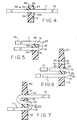
- Figures 4 through 8 show in schematic section, successive of steps of terminating a flat multiconductor ribbon cable with the connector assembly of the present invention.
- connector assembly 10 of the present invention is employed to terminate flat multiconductor ribbon cable 11 (Figs. 4 through 8).
- Connector assembly 10 includes an elongate connector base 12 comprised of electrically insulative plastic.
- Base 12 supports a plurality of electrical contacts 14, one of which is shown in Figure 1.
- Contacts 14 are fixably positioned within base 12, typically in plural longitudinally extending rows.
- Each contact 14 includes an upper insulation displacing end 16, which extends above an upper base surface 12a.
- Contact 14 includes a lower termination end 18 positioned adjacent a lower base surface 12b.
- Lower base surface 12b and the termination ends 18 of contacts 14 are designed for electrical interconnection with another electrical component, as will be described in greater detail hereinbelow.
- Insulation displacing ends 16 of contacts 14 may be similar to those of conventional construction and of the type used to electrically terminate conductors of flat multiconductor ribbon cable 11. Contacts 14 of this type are widely used in electrical connectors to facilitate easy mass termination of cable 11.
- Connector assembly 10 further includes a cover 20 which is an elongate member formed of insulative plastic extending longitudinally with base 12.
- Cover 20 includes a pair of opposed longitudinal sidewalls 22 and 24, and transverse end walls 26 and 28.
- Cover 20 further includes depending latch arms 30 and 32 extending from transverse end walls 26 and 28 respectively.
- Latch arms 30 and 32 cooperatively engage with transverse ends 34 and 36 of base 12 to permits movable latching engagement of cover 20 with base 12.
- Transverse ends 34 and 36 of base 12 include latch elements 38 which provide for the dual position latching of cover 20 to base 12.
- Extending between transverse end walls 26 and 28, cover 20 includes a longitudinal cover extend 40.
- Cover extend 40 includes an upper cover surface 42 and an opposed lower cover surface 44.
- Lower cover surface 44 may include undulations therealong (not shown) which engage flat multiconductor ribbon cable 11, as is known in the insulation displacing connection art.
- connection of contacts 14 to ribbon cable 11 is accomplished in a region 40a defined between lower surface 44 of cover 20 and upper surface 12a of base 12. Such connection may be achieved adjacent one end of ribbon cable 11 or may be accomplished along a central extend thereof (see Fig. 8). Termination in this manner allows cable 11 to be daisy-chain connected to additional connectors along its longitudinal extent.
- termination is achieved by moving cover 20 downard towards base 12 from an upper latched position to a lower latched position.
- a suitable tool (not shown) may be used to achieve such movement.
- Electrical connection assembly 10 further includes a header connector 50 designed for mating interconnection with base 12 and cover 20 which may be collectively referred to as socket connector 52.
- Header connector 50 is an elongate electrically insulative plastic member having a central cavity 54 which receives base 12 of socket connector 52.
- Header connector 50 supports a plurality of electrical terminals 56 which are arranged in a pattern that is complimentary to that of contacts 14. Insertable receipt of socket connector 52 into header connector 50 establishes electrical engagement between contacts 14 and terminals 56.
- Header connector 50 may be mounted to a printed circuit board (not shown) or the like, so that insertable and removable electrical connection may be established between cable 11 and the traces on the printed circuit board.
- Socket connector 52 and header connector 50 may include cooperative polarization devices such as projection 58 and slot 59 which facilitate the proper insertion of socket connector 52 into header connector 50. Such engagement is particularly shown in Figure 2.
- a pull-tab device 60 may be employed. Pull-tab device 60, in addition to serving its function of permitting easy insertion and withdrawal of socket connector 52 into header connector 50 also provides strain relief for the connection of ribbon cable 11 to contacts 14.
- Pull-tab device 60 includes an elongate body 62 formed of insulative plastic.
- Body 62 includes at each longitudinal end thereof spaced-apart depending legs 64 and 66.
- Legs 64 and 66 include latch mechanisms 67 which cooperatively engage with transverse end walls 26 and 28 of base 12 to secure pull-tab device 60 to socket connector 52.
- Depending legs 64 and 66 may also include a polarization key 69 which cooperates with corresponding recesses 71 within cavity 54 of header connector 50 so as to provide an additional polarization feature for the insertion of socket connector 52 into header connector 50.
- the cooperation of polarization key 69 with recess 71 of header connector 50 is shown in Figure 2.
- FIG. 3 shows a more preferred embodiment of the polarization feature of the connector assembly of present invention.
- Polarization key 69′ may be incorporated directly into one of depending legs 64′ of pull-tab device 60′ to serve a similar function.
- Pull-tab device 60 further includes a longitudinally extending containment bar 70 extending between depending legs 64 and 66.
- Containment bar 70 includes an upper containment bar surface 72 and an opposed lower containment bar surface 74.
- lower containment bar surface 74 cooperates with upper surface 42 of cover 20 to frictionally support a transverse extent of cable 11 therebetween.
- lowere containment bar surface 74 and upper cover surface 42 define a region 75 therebetween which accommodates cable 11.
- Region 75 is optimally designed to have a height which is slightly less than the height of cable 11 so that cable 11 is frictionally retained between lower containment bar surface 74 of containment bar 70 and upper surface 42 of cover 20.
- some cables could be compressibly clamped between containment bar 75 and cover 20 while other cables merely frictionally held thereby.
- Pull-tab device 60 further includes a longitudinal beam 76 extending between legs 64 and 66 above containment bar 70.
- Beam 76 is spaced from the upper surface 72 of containment bar 70 so as to define an elongate slot 79 therebetween.
- Slot 79 is defined by upper surface 72 of containment bar 70 and a lower surface 80 of beam 76.
- Slot 79 is positioned to receive an end of cable 11, which as will be described in further detail hereinbelow, is inserted therethrough.
- Slot 79 has a height which is slightly greater than the height of cable 11 to facilitate entry of the cable therethrough.
- Pull-tab device 60 further includes an extending projection 82 which extends from an upper surface 84 of beam 76.
- Projection 82 permits a user to manually grasp strain relief device 60, which is attached to socket connector 52 to facilitate insertion and removal of socket connector 52 from header connector 50.
- Gripping ribs 86 may be included along projection 82 to assist in the manula grasping thereof.
- an upper edge 88′ of projection 82 may be outwardly flared to further assist grasping (see Fig. 8).
- connector assembly 10 of the present invention Having described the structure of connector assembly 10 of the present invention, its use and operation may now be described.
- cable 11 is placed between base 12 and cover 20 of socket connector 52.
- a central transverse extent 11b of cable 11 is positioned in region 40a between the undersurface 44 of cover 20 and the upper surface 12a of base 12. It, however, may be understoof that the present invention may be practiced by placing an extent of cable 11 adjacent an end 11a thereof, between cover 20 and base 12. Cable 11 is terminated to socket connector 52 in a manner described above and well known in the insulation displacing electrical connector art.
- Cable 11 is bent back over cover 20 so that a further transverse extend 11c, spaced from extend 11b of cable 11, directly overlies upper surface 42 of cover 20. End 11a now extends in a direction opposite that shown in Figure 4.
- pull-tab device 60 is attached to socket connector 52. Transverse extent 11c of cable 11 is secured between lower containment bar surface 74 of containment bar 70 and upper surface 42 of cover 20. As the region 75 between lower containment bar surface 74 and upper surface 42 has a height which is designed to be slightly less than that of cable 11, cable 11 will be either compressed at extend 11c or frictionnally retained therein.
- end 11a is pulled through slot 79 until it is relatively taught. End 11a will now extend in the direction as originally shown in Figure 4. A further central extent 11d of cable 11 will be held within slot 79. As end 11a extends beyond socket connector 52 in the same direction as originally shown in Figure 4, cable 11 may be subsequently terminated anywhere along its length between transverse extent 11d and end 11a so that the cable 11 may be daisy-chain connected to other connectors.
- a daisy-chain connection of cable 11 is shown.
- the connection described hereinabove is shown on the left hand side of the drawing while an end termination, that is, a termination adjacent end 11a of cable 11 is shown in the right hand side of Figure 8.
- Socket connector 52′ terminates a transverse extent of cable 11 adjacent end 11a.
- Pull-tab 60′ is inserted over cover 20′ as described hereinabove. Since an end termination is achieved, there is no need to pull the end 11a through slot 79′ of pull-tab member 60′. It, of course, may be appreciated that several daisy-chain connections may be accomplished along the length of cable 11 in a manner described herein.
Landscapes
- Coupling Device And Connection With Printed Circuit (AREA)
- Multi-Conductor Connections (AREA)
Applications Claiming Priority (2)
| Application Number | Priority Date | Filing Date | Title |
|---|---|---|---|
| US707728 | 1991-05-30 | ||
| US07/707,728 US5108306A (en) | 1991-05-30 | 1991-05-30 | Method and apparatus for providing cable strain relief in an electrical connector assembly |
Publications (2)
| Publication Number | Publication Date |
|---|---|
| EP0516464A1 true EP0516464A1 (fr) | 1992-12-02 |
| EP0516464B1 EP0516464B1 (fr) | 1996-03-06 |
Family
ID=24842922
Family Applications (1)
| Application Number | Title | Priority Date | Filing Date |
|---|---|---|---|
| EP92304938A Expired - Lifetime EP0516464B1 (fr) | 1991-05-30 | 1992-05-29 | Appareillage pour le soulagement de traction pour câbles dans un assemblage de connecteurs électriques |
Country Status (5)
| Country | Link |
|---|---|
| US (1) | US5108306A (fr) |
| EP (1) | EP0516464B1 (fr) |
| CA (1) | CA2069377C (fr) |
| DE (1) | DE69208736T2 (fr) |
| ES (1) | ES2086655T3 (fr) |
Cited By (1)
| Publication number | Priority date | Publication date | Assignee | Title |
|---|---|---|---|---|
| WO2005008839A1 (fr) * | 2003-07-15 | 2005-01-27 | Siemens Aktiengesellschaft | Câble plat pourvu d'un dispositif de contact et appareil électrique doté d'un câble de ce type |
Families Citing this family (8)
| Publication number | Priority date | Publication date | Assignee | Title |
|---|---|---|---|---|
| US5626491A (en) * | 1995-08-18 | 1997-05-06 | The Whitaker Corporation | Electrical connector strain relief for cable |
| TW315998U (en) * | 1996-08-10 | 1997-09-11 | Hon Hai Prec Ind Co Ltd | Connector dedicated for computer bus |
| US6132236A (en) * | 1999-05-14 | 2000-10-17 | Methode Electronics, Inc. | Flex cable termination apparatus and termination method |
| TW422459U (en) * | 1999-06-17 | 2001-02-11 | Hon Hai Prec Ind Co Ltd | Electrical connector assembly |
| TW577650U (en) * | 2003-05-09 | 2004-02-21 | Hon Hai Prec Ind Co Ltd | Extraction device for electrical connector |
| US6855000B2 (en) * | 2003-07-14 | 2005-02-15 | Hon Hai Precision Ind. Co., Ltd. | Cable end connector assembly having pull tab |
| US8404974B1 (en) | 2011-11-17 | 2013-03-26 | Hubbell Incorporated | Stuffer cap for patch panel of rack system |
| DE102012025106A1 (de) * | 2012-12-21 | 2014-06-26 | Erni Production Gmbh & Co. Kg | Elektrischer Steckverbinder |
Citations (3)
| Publication number | Priority date | Publication date | Assignee | Title |
|---|---|---|---|---|
| US4006957A (en) * | 1974-09-25 | 1977-02-08 | Thomas & Betts Corporation | Connector |
| GB2033676A (en) * | 1978-10-16 | 1980-05-21 | Continental Wirt Electronic | Connector structure for flat cable |
| EP0043627A2 (fr) * | 1980-07-03 | 1982-01-13 | E.I. Du Pont De Nemours And Company | Connecteur pour un câble plat à plusieurs conducteurs |
Family Cites Families (17)
| Publication number | Priority date | Publication date | Assignee | Title |
|---|---|---|---|---|
| DE168048C (fr) * | ||||
| US2794155A (en) * | 1956-01-04 | 1957-05-28 | Emerson Radio & Phonograph Cor | Handling and locking structure for switchboard panel units |
| CH389056A (fr) * | 1961-06-05 | 1965-03-15 | Burndy Corp | Organe de connexion pour câble électrique |
| US3748628A (en) * | 1972-06-15 | 1973-07-24 | Gte Automatic Electric Lab Inc | Printed wiring cable termination |
| US3813634A (en) * | 1972-12-29 | 1974-05-28 | Burndy Corp | Strain relief for flat cable or the like |
| US3966293A (en) * | 1974-12-30 | 1976-06-29 | Bunker Ramo Corporation | Hood assembly for an electrical connector |
| US4025142A (en) * | 1975-12-17 | 1977-05-24 | Amp Incorporated | Cover for use with a ribbon coaxial cable connector |
| US4111512A (en) * | 1977-06-13 | 1978-09-05 | Amp Incorporated | Strain relief cover for flat flexible cable connector |
| US4305635A (en) * | 1979-11-02 | 1981-12-15 | Thomas & Betts Corporation | Flat conductor flat cable adaptor |
| US4295704A (en) * | 1979-12-03 | 1981-10-20 | Thomas & Betts Corporation | Side probeable connector using flat cable |
| US4460229A (en) * | 1981-04-01 | 1984-07-17 | Thomas & Betts Corporation | Flat cable connector having cover-cable retention |
| JPS6456152U (fr) * | 1987-10-01 | 1989-04-07 | ||
| SE459768B (sv) * | 1987-12-15 | 1989-07-31 | Asea Ab | Anordning foer att aastadkomma en kontaktfunktion hos ett relaeskyddsprovningssystem |
| US4932892A (en) * | 1988-09-28 | 1990-06-12 | Stewart Connector Systems, Inc. | High density connector for end terminating and/or daisy chaining flat cable and cable-connector assembly |
| US4938711A (en) * | 1989-01-30 | 1990-07-03 | Amp Incorporated | Strain relief for ribbon cable connectors |
| US4925401A (en) * | 1989-05-23 | 1990-05-15 | Amp Incorporated | Electrical connector assembly with strain relief |
| US5011430A (en) * | 1990-05-08 | 1991-04-30 | Thomas & Betts Corporation | Electrical connector having cable strain relief |
-
1991
- 1991-05-30 US US07/707,728 patent/US5108306A/en not_active Expired - Lifetime
-
1992
- 1992-05-25 CA CA002069377A patent/CA2069377C/fr not_active Expired - Fee Related
- 1992-05-29 DE DE69208736T patent/DE69208736T2/de not_active Expired - Fee Related
- 1992-05-29 ES ES92304938T patent/ES2086655T3/es not_active Expired - Lifetime
- 1992-05-29 EP EP92304938A patent/EP0516464B1/fr not_active Expired - Lifetime
Patent Citations (3)
| Publication number | Priority date | Publication date | Assignee | Title |
|---|---|---|---|---|
| US4006957A (en) * | 1974-09-25 | 1977-02-08 | Thomas & Betts Corporation | Connector |
| GB2033676A (en) * | 1978-10-16 | 1980-05-21 | Continental Wirt Electronic | Connector structure for flat cable |
| EP0043627A2 (fr) * | 1980-07-03 | 1982-01-13 | E.I. Du Pont De Nemours And Company | Connecteur pour un câble plat à plusieurs conducteurs |
Non-Patent Citations (1)
| Title |
|---|
| RESEARCH DISCLOSURE no. 309, January 1990, NEW YORK,US page 29; 'strain relief for insulation displacement connectors' * |
Cited By (1)
| Publication number | Priority date | Publication date | Assignee | Title |
|---|---|---|---|---|
| WO2005008839A1 (fr) * | 2003-07-15 | 2005-01-27 | Siemens Aktiengesellschaft | Câble plat pourvu d'un dispositif de contact et appareil électrique doté d'un câble de ce type |
Also Published As
| Publication number | Publication date |
|---|---|
| CA2069377C (fr) | 1994-12-13 |
| DE69208736D1 (de) | 1996-04-11 |
| EP0516464B1 (fr) | 1996-03-06 |
| ES2086655T3 (es) | 1996-07-01 |
| US5108306A (en) | 1992-04-28 |
| CA2069377A1 (fr) | 1992-12-01 |
| DE69208736T2 (de) | 1996-07-25 |
Similar Documents
| Publication | Publication Date | Title |
|---|---|---|
| US4711511A (en) | Latching apparatus for an electrical connector | |
| KR0146975B1 (ko) | 전기 커넥터 | |
| US4385794A (en) | Insulation displacement terminal | |
| EP1705755B1 (fr) | Connecteur électrique | |
| US4405193A (en) | Preloaded electrical connector | |
| JPS60253181A (ja) | 電気コネクタ | |
| EP0239422A1 (fr) | Connecteur électrique pour câble plat flexible | |
| KR970000284B1 (ko) | 관통 절연부 이동 판 터미널 | |
| JPH0460305B2 (fr) | ||
| EP0102798B1 (fr) | Serre-câble pour un connecteur électrique | |
| EP0516464B1 (fr) | Appareillage pour le soulagement de traction pour câbles dans un assemblage de connecteurs électriques | |
| EP0490542B1 (fr) | Moyens pour atténuer l'effort de tension pour contact à déplacement d'isolation | |
| US5921808A (en) | Ribbon cable plug-in connector | |
| US4886942A (en) | Strain relief structure for connecting flat flexible cable to a circuit board | |
| DE69022199D1 (de) | Torsionsschneidklemmverbinder. | |
| US5871369A (en) | Connector | |
| US4865561A (en) | PTC adaptor | |
| US4955816A (en) | Electrical connector system and insulation displacement terminals therefor | |
| US5119547A (en) | Means for separating male and female housings of an electric connector | |
| JPH08236250A (ja) | モジュール型電話コネクタのための終端処理用工具 | |
| US4522460A (en) | Connecting means for closely spaced conductors | |
| CA1146645A (fr) | Contact electrique pour connexion a un contact male a broche plate | |
| JP2002270285A (ja) | 歪み解放クランプを有するプラグコネクタ | |
| EP0570039A1 (fr) | Borne électrique | |
| JP2593330B2 (ja) | 平形多心信号伝送ケーブル用コネクタ及びその製造方法 |
Legal Events
| Date | Code | Title | Description |
|---|---|---|---|
| PUAI | Public reference made under article 153(3) epc to a published international application that has entered the european phase |
Free format text: ORIGINAL CODE: 0009012 |
|
| AK | Designated contracting states |
Kind code of ref document: A1 Designated state(s): BE CH DE ES FR GB IT LI LU NL SE |
|
| 17P | Request for examination filed |
Effective date: 19930526 |
|
| RAP3 | Party data changed (applicant data changed or rights of an application transferred) |
Owner name: THOMAS & BETTS CORPORATION |
|
| 17Q | First examination report despatched |
Effective date: 19940902 |
|
| GRAA | (expected) grant |
Free format text: ORIGINAL CODE: 0009210 |
|
| AK | Designated contracting states |
Kind code of ref document: B1 Designated state(s): BE CH DE ES FR GB IT LI LU NL SE |
|
| REG | Reference to a national code |
Ref country code: CH Ref legal event code: NV Representative=s name: BOVARD AG PATENTANWAELTE |
|
| REF | Corresponds to: |
Ref document number: 69208736 Country of ref document: DE Date of ref document: 19960411 |
|
| ET | Fr: translation filed | ||
| ITF | It: translation for a ep patent filed | ||
| REG | Reference to a national code |
Ref country code: ES Ref legal event code: FG2A Ref document number: 2086655 Country of ref document: ES Kind code of ref document: T3 |
|
| PLBE | No opposition filed within time limit |
Free format text: ORIGINAL CODE: 0009261 |
|
| STAA | Information on the status of an ep patent application or granted ep patent |
Free format text: STATUS: NO OPPOSITION FILED WITHIN TIME LIMIT |
|
| 26N | No opposition filed | ||
| REG | Reference to a national code |
Ref country code: FR Ref legal event code: TP Ref country code: FR Ref legal event code: CA |
|
| REG | Reference to a national code |
Ref country code: GB Ref legal event code: IF02 |
|
| PGFP | Annual fee paid to national office [announced via postgrant information from national office to epo] |
Ref country code: LU Payment date: 20040325 Year of fee payment: 13 |
|
| PGFP | Annual fee paid to national office [announced via postgrant information from national office to epo] |
Ref country code: BE Payment date: 20040603 Year of fee payment: 13 |
|
| PGFP | Annual fee paid to national office [announced via postgrant information from national office to epo] |
Ref country code: NL Payment date: 20050429 Year of fee payment: 14 |
|
| PGFP | Annual fee paid to national office [announced via postgrant information from national office to epo] |
Ref country code: SE Payment date: 20050519 Year of fee payment: 14 |
|
| PGFP | Annual fee paid to national office [announced via postgrant information from national office to epo] |
Ref country code: CH Payment date: 20050520 Year of fee payment: 14 |
|
| PG25 | Lapsed in a contracting state [announced via postgrant information from national office to epo] |
Ref country code: LU Free format text: LAPSE BECAUSE OF NON-PAYMENT OF DUE FEES Effective date: 20050529 |
|
| PG25 | Lapsed in a contracting state [announced via postgrant information from national office to epo] |
Ref country code: BE Free format text: LAPSE BECAUSE OF NON-PAYMENT OF DUE FEES Effective date: 20050531 |
|
| BERE | Be: lapsed |
Owner name: *THOMAS & BETTS CORP. Effective date: 20050531 |
|
| PG25 | Lapsed in a contracting state [announced via postgrant information from national office to epo] |
Ref country code: SE Free format text: LAPSE BECAUSE OF NON-PAYMENT OF DUE FEES Effective date: 20060530 |
|
| PG25 | Lapsed in a contracting state [announced via postgrant information from national office to epo] |
Ref country code: LI Free format text: LAPSE BECAUSE OF NON-PAYMENT OF DUE FEES Effective date: 20060531 Ref country code: CH Free format text: LAPSE BECAUSE OF NON-PAYMENT OF DUE FEES Effective date: 20060531 |
|
| PG25 | Lapsed in a contracting state [announced via postgrant information from national office to epo] |
Ref country code: NL Free format text: LAPSE BECAUSE OF NON-PAYMENT OF DUE FEES Effective date: 20061201 |
|
| REG | Reference to a national code |
Ref country code: CH Ref legal event code: PL |
|
| EUG | Se: european patent has lapsed | ||
| NLV4 | Nl: lapsed or anulled due to non-payment of the annual fee |
Effective date: 20061201 |
|
| PGFP | Annual fee paid to national office [announced via postgrant information from national office to epo] |
Ref country code: ES Payment date: 20070528 Year of fee payment: 16 |
|
| PGFP | Annual fee paid to national office [announced via postgrant information from national office to epo] |
Ref country code: DE Payment date: 20070702 Year of fee payment: 16 |
|
| PGFP | Annual fee paid to national office [announced via postgrant information from national office to epo] |
Ref country code: GB Payment date: 20070525 Year of fee payment: 16 |
|
| BERE | Be: lapsed |
Owner name: *THOMAS & BETTS CORP. Effective date: 20050531 |
|
| PGFP | Annual fee paid to national office [announced via postgrant information from national office to epo] |
Ref country code: IT Payment date: 20070526 Year of fee payment: 16 |
|
| PGFP | Annual fee paid to national office [announced via postgrant information from national office to epo] |
Ref country code: FR Payment date: 20070517 Year of fee payment: 16 |
|
| GBPC | Gb: european patent ceased through non-payment of renewal fee |
Effective date: 20080529 |
|
| REG | Reference to a national code |
Ref country code: FR Ref legal event code: ST Effective date: 20090119 |
|
| PG25 | Lapsed in a contracting state [announced via postgrant information from national office to epo] |
Ref country code: FR Free format text: LAPSE BECAUSE OF NON-PAYMENT OF DUE FEES Effective date: 20080602 Ref country code: DE Free format text: LAPSE BECAUSE OF NON-PAYMENT OF DUE FEES Effective date: 20081202 |
|
| PG25 | Lapsed in a contracting state [announced via postgrant information from national office to epo] |
Ref country code: GB Free format text: LAPSE BECAUSE OF NON-PAYMENT OF DUE FEES Effective date: 20080529 |
|
| REG | Reference to a national code |
Ref country code: ES Ref legal event code: FD2A Effective date: 20080530 |
|
| PG25 | Lapsed in a contracting state [announced via postgrant information from national office to epo] |
Ref country code: IT Free format text: LAPSE BECAUSE OF NON-PAYMENT OF DUE FEES Effective date: 20080529 |
|
| PG25 | Lapsed in a contracting state [announced via postgrant information from national office to epo] |
Ref country code: ES Free format text: LAPSE BECAUSE OF NON-PAYMENT OF DUE FEES Effective date: 20080530 |