EP0516523B1 - Assemblage discoide pour connecteurs à filtre - Google Patents
Assemblage discoide pour connecteurs à filtre Download PDFInfo
- Publication number
- EP0516523B1 EP0516523B1 EP92401424A EP92401424A EP0516523B1 EP 0516523 B1 EP0516523 B1 EP 0516523B1 EP 92401424 A EP92401424 A EP 92401424A EP 92401424 A EP92401424 A EP 92401424A EP 0516523 B1 EP0516523 B1 EP 0516523B1
- Authority
- EP
- European Patent Office
- Prior art keywords
- plate
- connector
- filter element
- filter
- apertures
- Prior art date
- Legal status (The legal status is an assumption and is not a legal conclusion. Google has not performed a legal analysis and makes no representation as to the accuracy of the status listed.)
- Expired - Lifetime
Links
- 239000003990 capacitor Substances 0.000 claims description 27
- 229910052751 metal Inorganic materials 0.000 claims description 11
- 239000002184 metal Substances 0.000 claims description 11
- 238000012360 testing method Methods 0.000 claims description 9
- 238000000034 method Methods 0.000 claims description 8
- 238000005476 soldering Methods 0.000 claims description 7
- 238000005452 bending Methods 0.000 claims description 3
- 239000004020 conductor Substances 0.000 claims description 3
- 239000000463 material Substances 0.000 claims description 3
- 229910000906 Bronze Inorganic materials 0.000 claims description 2
- OAICVXFJPJFONN-UHFFFAOYSA-N Phosphorus Chemical compound [P] OAICVXFJPJFONN-UHFFFAOYSA-N 0.000 claims description 2
- DMFGNRRURHSENX-UHFFFAOYSA-N beryllium copper Chemical compound [Be].[Cu] DMFGNRRURHSENX-UHFFFAOYSA-N 0.000 claims description 2
- 239000010974 bronze Substances 0.000 claims description 2
- KUNSUQLRTQLHQQ-UHFFFAOYSA-N copper tin Chemical compound [Cu].[Sn] KUNSUQLRTQLHQQ-UHFFFAOYSA-N 0.000 claims description 2
- 238000003780 insertion Methods 0.000 claims description 2
- 230000037431 insertion Effects 0.000 claims description 2
- 230000002093 peripheral effect Effects 0.000 claims 1
- 238000013461 design Methods 0.000 description 5
- 230000008901 benefit Effects 0.000 description 3
- 238000001914 filtration Methods 0.000 description 3
- 238000004382 potting Methods 0.000 description 3
- 229910000679 solder Inorganic materials 0.000 description 3
- 239000003989 dielectric material Substances 0.000 description 2
- 238000012986 modification Methods 0.000 description 2
- 230000004048 modification Effects 0.000 description 2
- 229910000859 α-Fe Inorganic materials 0.000 description 2
- 238000003491 array Methods 0.000 description 1
- 230000000712 assembly Effects 0.000 description 1
- 238000000429 assembly Methods 0.000 description 1
- 230000005540 biological transmission Effects 0.000 description 1
- 230000007613 environmental effect Effects 0.000 description 1
- 238000011065 in-situ storage Methods 0.000 description 1
- 238000002955 isolation Methods 0.000 description 1
- 238000007789 sealing Methods 0.000 description 1
- 230000035939 shock Effects 0.000 description 1
Images
Classifications
-
- H—ELECTRICITY
- H01—ELECTRIC ELEMENTS
- H01R—ELECTRICALLY-CONDUCTIVE CONNECTIONS; STRUCTURAL ASSOCIATIONS OF A PLURALITY OF MUTUALLY-INSULATED ELECTRICAL CONNECTING ELEMENTS; COUPLING DEVICES; CURRENT COLLECTORS
- H01R13/00—Details of coupling devices of the kinds covered by groups H01R12/70 or H01R24/00 - H01R33/00
- H01R13/66—Structural association with built-in electrical component
- H01R13/719—Structural association with built-in electrical component specially adapted for high frequency, e.g. with filters
Definitions
- the present invention relates to electrical connectors and in particular to an electrical connector filter assembly.
- a main problem in assembling a filter connector lies in establishing electrical connections between the individual filter elements and the signal carrying connector contacts on the one hand, and between the filter elements and a common ground on the other. It is of course essential that all electrical connections be secure, with as low an impedance as possible, but it is also desirable for the connections to be releasable, permitting in situ testing and subsequent repair of the filter component without having to discard the entire connector prior to completion of the connector by potting.
- a typical connector having a diameter of approximately 1 ⁇ may carry more than 50 feedthrough signal contacts, each contact requiring filtering.
- the problem of providing a filter for each contact is simplified somewhat by using monolithic filter elements, in which the filter elements are in the form of blocks of dielectric material with buried interleaved electrodes, but such filter elements are fragile, relatively expensive, and difficult to customize for specific applications.
- monolithic filter elements are subject to design problems involving cross-talk, hole-to-hole capacitance, ground resistance and control of the capacitance of non-filter holes. These problems arise because the live electrodes in each of the holes are separated from each other only by the dielectric material, and because each hole, whether filtered or not, is surrounded by the dielectric.
- the invention is defined by the features of claim 1.
- a filter assembly which includes a stamped and formed metal plate of resilient conductive material including a plurality of feedthrough signal contact apertures and a plurality of tines extending radially outwardly from the periphery of the plate, the tines being bent to resiliently engage a connector shell and thereby establish electrical contact therewith.
- a plurality of discoidal filter elements are arranged on the plate such that central apertures of the filter elements are coaxial with the plate apertures. Electrical connection between the ground electrodes of the filter elements and the ground plate is effected by soldering portions of the ground electrode directly to the surface of the plate. As a result, no special modification of the plate is required, and connection may be established by simply placing the filter elements in position and soldering.
- the ground plate apertures of the preferred embodiment have a diameter larger than the filter element apertures.
- the outer diameters of the filter elements are, according to the preferred embodiment, greater than the ground plate aperture diameters.
- assembly of the connector for testing involves simply inserting the ground plane into the connector, and the pins into the filters, both via solderless connections.
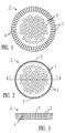
- Figure 1 is an elevated view of a ground plate for use in a filter assembly according to a preferred embodiment of the invention.
- Figure 2 shows the ground plate of Figure 1 after bending of its integral spring tines.
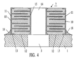
- Figure 3 is a cross-sectional side view taken along line I-I of Figure 2.
- Figure 4 is a cross-sectional side view showing the manner in which filter elements are mounted on the ground plate of Figures 1-3.
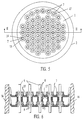
- Figure 5 is an elevated plan view of the filter assembly of Figures 1-4.
- Figure 6 is a cross-sectional side view of a connector taken along line II-II of Figure 5 and showing the manner in which the filter assembly of Figure 3 is arranged to form a connector pi filter assembly.
- the preferred embodiment of the invention includes a ground plate 1 which is stamped and formed from a metal sheet to include a plurality of tines 2 provided for the purpose of establishing an electrical connection between the plate and the shell 16 of the connector, and a plurality of apertures 3 in which the feedthrough contacts of the connector are arranged as described in detail below.
- a preferred material for the plate is phosphor bronze, although other resilient conductive materials may be substituted, for example beryllium copper.
- the purpose of providing a resilient metal plate is to impart a radially outwardly directed biasing force to the tines upon causing them to bend beyond the position shown in Figures 2 and 3 when inserting the ground plate in a connector, which causes the tines to securely engage the metal shell of the connector to ensure a good ground connection for the filter elements.
- Tines 2 are formed by stamping slots 4 in the periphery of a circular blank, as shown in Figure 1, and then bending the tines to form an oblique angle in respect to a principal plane of the plate, as shown in Figures 2 and 3, such that the distance between diametrically opposite shell-engaging distal portions 5 of the tines is larger than an inner diameter of the connector shell at the point where the inserted plate contacts the shell to establish an electrical connection between the plate and the shell 16.
- a radially outwardly directed biasing force is thus obtained upon insertion of the plate into the shell, as a result of the consequent deflection of the tines in a radially inward direction.
- the use of stamped and formed continuous spring tines about the periphery of the ground plate has several advantages.
- the spring arrangement In addition to permitting solderless assembly of the ground plate into the connector shell, the spring arrangement possesses low inductance due to the existence of multiple parallel ground paths, and low resistance due to the existence of multiple independent ground paths.
- the filter array can be tested in the connector shell and then removed for repair if necessary prior to potting.
- the filter assembly is completed by soldering discoidal filter elements to the ground plate so that inner apertures of the filter elements through which the feedthrough signal contacts pass are substantially coaxial with the centers of the apertures in the ground plate.
- the filter elements are pre-manufactured discoidal capacitors, including outer electrodes 10 made up of circumferential portions 11 and lower portions 13 extending along planar annular surface 12.
- the capacitors are electrically connected to plate 1 via solder fillets 18, which connect plate 1 to electrode portions 11 and 13, thus permitting the capacitors to be connected to the plate by simply aligning the capacitors and soldering.
- solder fillets the outer diameters of the capacitors must be greater than the diameters of the ground plate apertures as shown, and that the solder fillets should substantially surround the capacitors.
- contact pins 6 are provided with compliant sections 8 having a diameter which is larger than the diameter of apertures 14.
- compliant sections 8 flex radially inward, the restoring force on the compliant sections serving to ensure good electrical contact between contacts 6 and electrodes 15 of capacitors 7. It will be appreciated that the preferred solderless contact arrangement will work best if the diameters of apertures 3 are sufficiently large that the compliant sections do not touch the ground plate.
- the inductors are preferably in the form of ferrite inductor sleeves 17 sandwiched between the capacitive filter structures as is known in the art, although numerous other inductor structures may be substituted.
- the assembly is then oriented by an insert (not shown) keyed to a key on the shell or by a key in a tool.
- suitable insert structures are known to those skilled in the art for the purpose of providing support, shock protection, alignment, and environmental sealing for connector filter assemblies.
- Assembly of the above-described structures is accomplished by soldering the capacitors to the plates, preferably by using solder pads, subsequently inserting feedthrough contact pins into central apertures of the capacitors, adding appropriate support inserts, and inserting the assembly into the shell to cause tines on the ground plate to deflect and establish an electrical connection between the ground plate and the shell.
- the filter may be tested and, if the tests are satisfactory, secured within the shell by potting, dielectric inserts, or similar means. If the filter fails the tests, then the filter assembly or individual contacts may easily be removed for repair or replacement.
Landscapes
- Details Of Connecting Devices For Male And Female Coupling (AREA)
Claims (16)
- Ensemble de filtrage pour connecteur électrique, comprenant :
une plaque de masse formée d'un métal conducteur élastique ayant un dispositif délimitant plusieurs orifices dans la plaque, un dispositif de mise à la masse destiné à connecter électriquement la plaque à l'enveloppe d'un connecteur, au moins un élément de filtrage en forme de disque qui comporte une électrode interne délimitant un orifice central de l'élément de filtrage et une électrode externe, et un dispositif de connexion d'électrode de masse destiné à connecter électriquement l'électrode externe à la surface de la plaque, caractérisé en ce que l'élément de filtrage en forme de disque est fixé à une surface de la plaque de manière qu'un axe principal de l'élément de filtrage passe par le centre de l'un des orifices. - Ensemble de filtrage selon la revendication 1, caractérisé en ce que la plaque de masse est emboutie et mise en forme, et le dispositif de mise à la masse comprend plusieurs dents dépassant radialement à l'extérieur de la périphérie de la plaque et inclinées obliquement par rapport au plan principal de la plaque.
- Ensemble de filtrage selon la revendication 2, caractérisé en ce que la distance comprise entre les extrémités périphériques diamétralement opposées des dents est supérieure au diamètre interne d'un connecteur dans lequel doit être introduit l'ensemble de filtrage, si bien que les dents fléchissent vers l'intérieur lors de l'introduction de l'ensemble dans le connecteur.
- Connecteur électrique, comprenant un ensemble de filtrage selon la revendication 1, caractérisé en outre en ce qu'il comprend une enveloppe, et en ce que le dispositif de mise à la masse comprend plusieurs dents dépassant radialement vers l'extérieur de la périphérie de la plaque et destinées à établir une connexion électrique entre la plaque et l'enveloppe, les dents ayant des axes principaux disposés obliquement par rapport à un plan principal de la plaque, et
caractérisé en outre en ce que l'élément de filtrage en forme de disque comporte un orifice central pratiquement cylindrique et une périphérie externe pratiquement cylindrique, le diamètre de l'orifice central étant inférieur au diamètre de l'un des orifices de la plaque, et le diamètre de la périphérie externe étant supérieur au diamètre de l'un des orifices de la plaque. - Ensemble de filtrage selon la revendication 1 ou 4, caractérisé en ce que l'élément de filtrage est un condensateur, et l'électrode externe entoure pratiquement le condensateur, si bien que l'électrode externe est utilisée pour l'isolement électrique du condensateur.
- Connecteur selon la revendication 1 ou 4, caractérisé en ce que l'élément de filtrage en forme de disque comporte une électrode interne cylindrique délimitant un orifice central, et une électrode externe qui comporte une partie circonférentielle d'électrode entourant l'élément de filtrage, et dans lequel la partie d'électrode externe est soudée avec apport à une surface plane de la plaque sur laquelle est positionné l'élément de filtrage.
- Ensemble de filtrage selon la revendication 1 ou 4, caractérisé en ce que le matériau est le bronze phosphoreux.
- Ensemble de filtrage selon la revendication 1 ou 4, caractérisé en ce que le matériau est le cuivre au béryllium.
- Connecteur selon la revendication 4, caractérisé en ce que le connecteur comporte plusieurs contacts de traversée destinés à passer dans les orifices, l'un au moins des contacts ayant un dispositif élastique destiné à coopérer élastiquement avec l'électrode interne de l'élément de filtrage afin qu'il établisse ainsi une connexion électrique entre le contact au moins et l'électrode interne, et maintienne temporairement le contact dans l'orifice de l'élément de filtrage.
- Connecteur selon la revendication 9, caractérisé en ce que le dispositif élastique comporte un tronçon élastique dudit contact.
- Connecteur selon la revendication 9, caractérisé en ce qu'il comporte en outre un manchon inducteur entourant ledit contact au moins, et une seconde plaque métallique emboutie et mise en forme en un matériau conducteur élastique, comprenant un dispositif délimitant plusieurs seconds orifices dans la plaque et plusieurs secondes dents dépassant radialement à l'extérieur de la périphérie de la plaque, les secondes dents étant inclinées par rapport au plan principal de la seconde plaque, et au moins un second élément de filtrage en forme de disque placé sur la seconde plaque de manière que l'axe principal de l'élément de filtrage passe par le centre de l'un des seconds orifices, et dans lequel le second élément de filtrage en forme de disque comporte un second orifice central pratiquement cylindrique et une seconde périphérie externe pratiquement cylindrique, le diamètre du second orifice central étant inférieur au diamètre dudit orifice de la seconde plaque, et le diamètre de la seconde périphérie externe étant supérieur au diamètre dudit orifice de la seconde plaque.
- Procédé de montage d'un ensemble de filtrage de connecteur, comprenant des étapes d'emboutissage et de mise en forme d'une plaque métallique pour la formation d'une plaque métallique emboutie et mise en forme, comprenant plusieurs orifices de plaque et plusieurs dents élastiques dépassant à la périphérie de la plaque, et le pliage des dents afin qu'elles soient disposées en oblique par rapport à un plan principal de la plaque, et caractérisé en ce qu'il comporte en outre les étapes suivantes :
l'alignement d'un orifice cylindrique d'au moins un élément de filtrage en forme de disque sur l'un des orifices de la plaque,
la fixation de l'élément de filtrage à la plaque métallique, et
la connexion électrique d'une partie d'électrode externe de l'élément de filtrage à une surface de la plaque sur laquelle est positionné l'élément de filtrage. - Procédé de montage d'un connecteur, comprenant les étapes indiquées dans la revendication 12, et caractérisé en outre par l'étape d'introduction de l'ensemble de filtrage dans un connecteur de manière que les dents soient au contact d'une enveloppe du connecteur et soient déviées radialement vers l'intérieur par cette enveloppe pour l'établissement d'une connexion électrique positive entre la plaque et l'enveloppe.
- Procédé selon la revendication 12 ou 13, caractérisé en ce que l'étape de connexion comprend l'étape de soudage avec apport de parties d'électrode externe à la plaque.
- Procédé selon la revendication 13, caractérisé en outre par l'étape d'introduction de contacts de traversée dans les orifices centraux des éléments de filtrage afin que des tronçons élastiques des contacts fléchissent radialement vers l'intérieur lors de la mise en contact avec des électrodes internes pratiquement cylindriques des condensateurs pour l'établissement d'une connexion électrique entre les électrodes internes et les contacts.
- Procédé selon la revendication 15, caractérisé en outre par l'étape de test du connecteur avant la fixation permanente de la plaque, des éléments de filtrage et des contacts dans le connecteur, et l'enlèvement de la plaque et des éléments de filtrage ou des contacts lorsque le connecteur ne donne pas un résultat satisfaisant après le test.
Applications Claiming Priority (2)
| Application Number | Priority Date | Filing Date | Title |
|---|---|---|---|
| US707095 | 1991-05-29 | ||
| US07/707,095 US5287076A (en) | 1991-05-29 | 1991-05-29 | Discoidal array for filter connectors |
Publications (3)
| Publication Number | Publication Date |
|---|---|
| EP0516523A2 EP0516523A2 (fr) | 1992-12-02 |
| EP0516523A3 EP0516523A3 (en) | 1993-04-14 |
| EP0516523B1 true EP0516523B1 (fr) | 1995-11-15 |
Family
ID=24840331
Family Applications (1)
| Application Number | Title | Priority Date | Filing Date |
|---|---|---|---|
| EP92401424A Expired - Lifetime EP0516523B1 (fr) | 1991-05-29 | 1992-05-25 | Assemblage discoide pour connecteurs à filtre |
Country Status (5)
| Country | Link |
|---|---|
| US (1) | US5287076A (fr) |
| EP (1) | EP0516523B1 (fr) |
| CA (1) | CA2069704A1 (fr) |
| DE (2) | DE516523T1 (fr) |
| IL (1) | IL101984A (fr) |
Families Citing this family (82)
| Publication number | Priority date | Publication date | Assignee | Title |
|---|---|---|---|---|
| DE4327850C2 (de) * | 1993-08-19 | 1997-04-03 | Filtec Gmbh | Planarfilter insbesondere für mehrpolige Steckverbinder mit Stecker und Gegenstecker |
| US5650759A (en) * | 1995-11-09 | 1997-07-22 | Hittman Materials & Medical Components, Inc. | Filtered feedthrough assembly having a mounted chip capacitor for medical implantable devices and method of manufacture therefor |
| US5817130A (en) * | 1996-05-03 | 1998-10-06 | Sulzer Intermedics Inc. | Implantable cardiac cardioverter/defibrillator with EMI suppression filter with independent ground connection |
| JP3269434B2 (ja) * | 1997-09-05 | 2002-03-25 | 株式会社村田製作所 | 電子部品 |
| US6120326A (en) * | 1999-10-21 | 2000-09-19 | Amphenol Corporation | Planar-tubular composite capacitor array and electrical connector |
| US6349025B1 (en) | 1999-11-30 | 2002-02-19 | Medtronic, Inc. | Leak testable capacitive filtered feedthrough for an implantable medical device |
| US6414835B1 (en) | 2000-03-01 | 2002-07-02 | Medtronic, Inc. | Capacitive filtered feedthrough array for an implantable medical device |
| US6477032B2 (en) * | 2001-01-31 | 2002-11-05 | Avx Corporation | Low inductance chip with center via contact |
| US7295086B2 (en) * | 2002-10-23 | 2007-11-13 | Spectrum Control Inc. | Dielectric component array with failsafe link |
| DE10349301A1 (de) * | 2002-10-23 | 2004-06-03 | Spectrum Control Inc. | Anordnung dielektrischer Bauteile |
| TWM244634U (en) * | 2003-10-08 | 2004-09-21 | Taiwan Cable Connection Corp | Radio frequency adapting device |
| US7285018B2 (en) | 2004-06-23 | 2007-10-23 | Amphenol Corporation | Electrical connector incorporating passive circuit elements |
| US7210966B2 (en) | 2004-07-12 | 2007-05-01 | Medtronic, Inc. | Multi-polar feedthrough array for analog communication with implantable medical device circuitry |
| US20090291593A1 (en) | 2005-06-30 | 2009-11-26 | Prescott Atkinson | High frequency broadside-coupled electrical connector |
| US20110048770A1 (en) | 2009-08-31 | 2011-03-03 | Medtronic Inc. | Injection molded ferrule for cofired feedthroughs |
| CN102906947B (zh) | 2009-11-13 | 2016-04-13 | 安费诺有限公司 | 高性能、小形状因数的带有常规模式电抗控制的连接器 |
| EP2539971A4 (fr) | 2010-02-24 | 2014-08-20 | Amphenol Corp | Connecteur à grande largeur de bande |
| CN107069274B (zh) | 2010-05-07 | 2020-08-18 | 安费诺有限公司 | 高性能线缆连接器 |
| US20110287663A1 (en) | 2010-05-21 | 2011-11-24 | Gailus Mark W | Electrical connector incorporating circuit elements |
| US8382524B2 (en) | 2010-05-21 | 2013-02-26 | Amphenol Corporation | Electrical connector having thick film layers |
| WO2012106554A2 (fr) | 2011-02-02 | 2012-08-09 | Amphenol Corporation | Connecteur de type mezzanine |
| US8644002B2 (en) | 2011-05-31 | 2014-02-04 | Medtronic, Inc. | Capacitor including registration feature for aligning an insulator layer |
| US20130058004A1 (en) | 2011-09-01 | 2013-03-07 | Medtronic, Inc. | Feedthrough assembly including underfill access channel and electrically insulating material |
| WO2013059317A1 (fr) | 2011-10-17 | 2013-04-25 | Amphenol Corporation | Connecteur électrique à blindage hybride |
| US8591257B2 (en) | 2011-11-17 | 2013-11-26 | Amphenol Corporation | Electrical connector having impedance matched intermediate connection points |
| US8644936B2 (en) | 2012-01-09 | 2014-02-04 | Medtronic, Inc. | Feedthrough assembly including electrical ground through feedthrough substrate |
| CN108336593B (zh) | 2012-06-29 | 2019-12-17 | 安费诺有限公司 | 低成本高性能的射频连接器 |
| WO2014031851A1 (fr) | 2012-08-22 | 2014-02-27 | Amphenol Corporation | Connecteur électrique haute fréquence |
| US9025315B2 (en) | 2013-03-06 | 2015-05-05 | Cooper Technologies Company | Electrochemical energy storage device with flexible metal current collector |
| WO2014160356A1 (fr) | 2013-03-13 | 2014-10-02 | Amphenol Corporation | Boîtier pour un connecteur électrique de vitesse |
| US9484674B2 (en) | 2013-03-14 | 2016-11-01 | Amphenol Corporation | Differential electrical connector with improved skew control |
| CA2960991C (fr) | 2013-11-01 | 2020-06-30 | Quell Corporation | Garniture de connecteur electrique flexible a tres faible inductance |
| US9692188B2 (en) | 2013-11-01 | 2017-06-27 | Quell Corporation | Flexible electrical connector insert with conductive and non-conductive elastomers |
| CN121367083A (zh) | 2014-01-22 | 2026-01-20 | 安费诺有限公司 | 电连接器、子组件、模块、线缆组件、电气组件及电路板 |
| US9472904B2 (en) | 2014-08-18 | 2016-10-18 | Amphenol Corporation | Discrete packaging adapter for connector |
| CN107112696B (zh) | 2014-11-12 | 2020-06-09 | 安费诺有限公司 | 在配合区域中具有阻抗控制的非常高速、高密度电互连系统 |
| US9585255B2 (en) | 2015-03-11 | 2017-02-28 | Raytheon Company | Component support for dense circuit board |
| US10541482B2 (en) | 2015-07-07 | 2020-01-21 | Amphenol Fci Asia Pte. Ltd. | Electrical connector with cavity between terminals |
| CN108028481B (zh) | 2015-07-23 | 2021-08-20 | 安费诺有限公司 | 用于模块化连接器的延伸器模块 |
| CN109565137A (zh) | 2016-05-31 | 2019-04-02 | 安费诺有限公司 | 高性能线缆终端装置 |
| WO2017209694A1 (fr) | 2016-06-01 | 2017-12-07 | Amphenol Fci Connectors Singapore Pte. Ltd. | Connecteur électrique à grande vitesse |
| CN111755867B (zh) | 2016-08-23 | 2022-09-20 | 安费诺有限公司 | 可配置为高性能的连接器 |
| CN115189188A (zh) | 2016-10-19 | 2022-10-14 | 安费诺有限公司 | 柔性屏蔽件、电连接器及电子装置 |
| WO2018226344A1 (fr) * | 2017-06-09 | 2018-12-13 | Medtronic, Inc. | Ensemble de traversée comprenant une virole avec une ou plusieurs extensions effilées |
| CN119209123A (zh) | 2017-08-03 | 2024-12-27 | 安费诺有限公司 | 用于高速互连的线缆连接器 |
| WO2019084717A1 (fr) | 2017-10-30 | 2019-05-09 | Amphenol Fci Asia Pte Ltd | Connecteur de bord de carte à faible diaphonie |
| US10601181B2 (en) | 2017-12-01 | 2020-03-24 | Amphenol East Asia Ltd. | Compact electrical connector |
| US10777921B2 (en) | 2017-12-06 | 2020-09-15 | Amphenol East Asia Ltd. | High speed card edge connector |
| US10665973B2 (en) | 2018-03-22 | 2020-05-26 | Amphenol Corporation | High density electrical connector |
| WO2019195319A1 (fr) | 2018-04-02 | 2019-10-10 | Ardent Concepts, Inc. | Extrémité de câble souple à impédance contrôlée |
| CN208862209U (zh) | 2018-09-26 | 2019-05-14 | 安费诺东亚电子科技(深圳)有限公司 | 一种连接器及其应用的pcb板 |
| CN113169484A (zh) | 2018-10-09 | 2021-07-23 | 安费诺商用电子产品(成都)有限公司 | 高密度边缘连接器 |
| TWM576774U (zh) | 2018-11-15 | 2019-04-11 | 香港商安費諾(東亞)有限公司 | 具有防位移結構之金屬殼體及其連接器 |
| US10931062B2 (en) | 2018-11-21 | 2021-02-23 | Amphenol Corporation | High-frequency electrical connector |
| US11381015B2 (en) | 2018-12-21 | 2022-07-05 | Amphenol East Asia Ltd. | Robust, miniaturized card edge connector |
| CN117175239A (zh) | 2019-01-25 | 2023-12-05 | 富加宜(美国)有限责任公司 | 插座连接器和电连接器 |
| WO2020154526A1 (fr) | 2019-01-25 | 2020-07-30 | Fci Usa Llc | Connecteur d'e/s configuré pour une connexion câblée à la carte intermédiaire |
| US11189971B2 (en) | 2019-02-14 | 2021-11-30 | Amphenol East Asia Ltd. | Robust, high-frequency electrical connector |
| CN111585098B (zh) | 2019-02-19 | 2025-08-19 | 安费诺有限公司 | 高速连接器 |
| CN113728521B (zh) | 2019-02-22 | 2025-03-18 | 安费诺有限公司 | 高性能线缆连接器组件 |
| TWM582251U (zh) | 2019-04-22 | 2019-08-11 | 香港商安費諾(東亞)有限公司 | Connector set with built-in locking mechanism and socket connector thereof |
| CN114128053B (zh) | 2019-05-20 | 2024-10-11 | 安费诺有限公司 | 高密度高速电连接器 |
| CN114788097A (zh) | 2019-09-19 | 2022-07-22 | 安费诺有限公司 | 具有中间板线缆连接器的高速电子系统 |
| US11588277B2 (en) | 2019-11-06 | 2023-02-21 | Amphenol East Asia Ltd. | High-frequency electrical connector with lossy member |
| US11799230B2 (en) | 2019-11-06 | 2023-10-24 | Amphenol East Asia Ltd. | High-frequency electrical connector with in interlocking segments |
| CN115428275B (zh) | 2020-01-27 | 2025-12-30 | 富加宜(美国)有限责任公司 | 高速连接器 |
| WO2021154718A1 (fr) | 2020-01-27 | 2021-08-05 | Fci Usa Llc | Connecteur orthogonal à accouplement direct à haute densité et à grande vitesse |
| CN113258325A (zh) | 2020-01-28 | 2021-08-13 | 富加宜(美国)有限责任公司 | 高频中板连接器 |
| TWM625349U (zh) | 2020-03-13 | 2022-04-11 | 大陸商安費諾商用電子產品(成都)有限公司 | 加強部件、電連接器、電路板總成及絕緣本體 |
| US11728585B2 (en) | 2020-06-17 | 2023-08-15 | Amphenol East Asia Ltd. | Compact electrical connector with shell bounding spaces for receiving mating protrusions |
| US11831092B2 (en) | 2020-07-28 | 2023-11-28 | Amphenol East Asia Ltd. | Compact electrical connector |
| US11652307B2 (en) | 2020-08-20 | 2023-05-16 | Amphenol East Asia Electronic Technology (Shenzhen) Co., Ltd. | High speed connector |
| CN212874843U (zh) | 2020-08-31 | 2021-04-02 | 安费诺商用电子产品(成都)有限公司 | 电连接器 |
| CN215816516U (zh) | 2020-09-22 | 2022-02-11 | 安费诺商用电子产品(成都)有限公司 | 电连接器 |
| CN213636403U (zh) | 2020-09-25 | 2021-07-06 | 安费诺商用电子产品(成都)有限公司 | 电连接器 |
| US12407123B1 (en) | 2020-11-23 | 2025-09-02 | Quell Corporation | Electrically dissipative flexible unitary connector insert |
| US11569613B2 (en) | 2021-04-19 | 2023-01-31 | Amphenol East Asia Ltd. | Electrical connector having symmetrical docking holes |
| US12176650B2 (en) | 2021-05-05 | 2024-12-24 | Amphenol East Asia Limited (Hong Kong) | Electrical connector with guiding structure and mating groove and method of connecting electrical connector |
| CN215266741U (zh) | 2021-08-13 | 2021-12-21 | 安费诺商用电子产品(成都)有限公司 | 一种满足高带宽传输的高性能卡类连接器 |
| USD1002553S1 (en) | 2021-11-03 | 2023-10-24 | Amphenol Corporation | Gasket for connector |
| USD1068685S1 (en) | 2021-12-14 | 2025-04-01 | Amphenol Corporation | Electrical connector |
| USD1067191S1 (en) | 2021-12-14 | 2025-03-18 | Amphenol Corporation | Electrical connector |
Family Cites Families (17)
| Publication number | Priority date | Publication date | Assignee | Title |
|---|---|---|---|---|
| CA870243A (en) * | 1971-05-04 | Erie Technological Products | Multiple pin connector having ferrite core stacked capacitor filter | |
| US3538464A (en) * | 1963-08-20 | 1970-11-03 | Erie Technological Prod Inc | Multiple pin connector having ferrite core stacked capacitor filter |
| US3569915A (en) * | 1968-09-16 | 1971-03-09 | Itt | Grounding foil |
| US3790858A (en) * | 1973-01-29 | 1974-02-05 | Itt | Electrical connector with component grounding plate |
| US3825874A (en) * | 1973-07-05 | 1974-07-23 | Itt | Electrical connector |
| BR7508698A (pt) * | 1975-01-08 | 1976-08-24 | Bunker Ramo | Conjunto de filtro para conector |
| US4083022A (en) * | 1976-10-12 | 1978-04-04 | Bunker Ramo Corporation | Planar pi multi-filter having a ferrite inductance for pin filters in electrical connectors |
| US4148003A (en) * | 1977-07-08 | 1979-04-03 | Globe-Union Inc. | Series feed-through capacitor |
| US4275945A (en) * | 1979-08-31 | 1981-06-30 | The Bendix Corporation | Filter connector with compound filter elements |
| US4458220A (en) * | 1981-07-17 | 1984-07-03 | Automation Industries, Inc. | Electrical connector and filter circuit |
| US4494092A (en) * | 1982-07-12 | 1985-01-15 | The Deutsch Company Electronic Components Division | Filter pin electrical connector |
| GB8610665D0 (en) * | 1986-05-01 | 1986-06-04 | Oxley Dev Co Ltd | Filtered electrical connectors |
| US4741710A (en) * | 1986-11-03 | 1988-05-03 | Amphenol Corporation | Electrical connector having a monolithic capacitor |
| US4768977A (en) * | 1986-11-03 | 1988-09-06 | Amphenol Corporation | Electrical contact with transient suppression |
| US4954794A (en) * | 1989-04-10 | 1990-09-04 | Itt Corporation | Filter contact |
| US4950185A (en) * | 1989-05-18 | 1990-08-21 | Amphenol Corporation | Stress isolated planar filter design |
| US5153540A (en) * | 1991-04-01 | 1992-10-06 | Amphenol Corporation | Capacitor array utilizing a substrate and discoidal capacitors |
-
1991
- 1991-05-29 US US07/707,095 patent/US5287076A/en not_active Expired - Fee Related
-
1992
- 1992-05-25 DE DE199292401424T patent/DE516523T1/de active Pending
- 1992-05-25 DE DE69206046T patent/DE69206046T2/de not_active Expired - Fee Related
- 1992-05-25 IL IL10198492A patent/IL101984A/en not_active IP Right Cessation
- 1992-05-25 EP EP92401424A patent/EP0516523B1/fr not_active Expired - Lifetime
- 1992-05-27 CA CA002069704A patent/CA2069704A1/fr not_active Abandoned
Also Published As
| Publication number | Publication date |
|---|---|
| IL101984A0 (en) | 1992-12-30 |
| US5287076A (en) | 1994-02-15 |
| EP0516523A3 (en) | 1993-04-14 |
| DE516523T1 (de) | 1993-06-09 |
| EP0516523A2 (fr) | 1992-12-02 |
| CA2069704A1 (fr) | 1992-11-30 |
| DE69206046D1 (de) | 1995-12-21 |
| DE69206046T2 (de) | 1996-07-11 |
| IL101984A (en) | 1995-10-31 |
Similar Documents
| Publication | Publication Date | Title |
|---|---|---|
| US5287076A (en) | Discoidal array for filter connectors | |
| US5153540A (en) | Capacitor array utilizing a substrate and discoidal capacitors | |
| US4083022A (en) | Planar pi multi-filter having a ferrite inductance for pin filters in electrical connectors | |
| US6120326A (en) | Planar-tubular composite capacitor array and electrical connector | |
| EP0398807B1 (fr) | Filtre à structure plane isolé d'efforts mécaniques | |
| US6882248B2 (en) | EMI filtered connectors using internally grounded feedthrough capacitors | |
| US4660907A (en) | EMI filter connector block | |
| US4952896A (en) | Filter assembly insertable into a substrate | |
| US4079343A (en) | Connector filter assembly | |
| US5236376A (en) | Connector | |
| CA1138538A (fr) | Raccord de filtre a elements filtrants multiples | |
| US4729743A (en) | Filtered electrical connector | |
| US4401355A (en) | Filtered connector | |
| US4260966A (en) | High current filter connector with removable contact members | |
| US4781624A (en) | Filter arrangements and connectors | |
| US5242318A (en) | Multipole connector for electronic signal lines | |
| EP0437606B1 (fr) | Connecteurs electriques | |
| CA2289140A1 (fr) | Module de connecteur coaxial incline | |
| US4853659A (en) | Planar pi-network filter assembly having capacitors formed on opposing surfaces of an inductive member | |
| EP0339802B1 (fr) | Assemblage de filtrage démontable pour connecteurs multicanaux | |
| EP0677215A1 (fr) | Connecteur a blindage ameliore | |
| US4792310A (en) | Connector having filtering function | |
| US4674815A (en) | Electrical connectors | |
| US5379012A (en) | Dielectric filter device | |
| JP2004523061A (ja) | 肩部コンタクトを備えた端子台ならびにプラスチックインサートによって保持された成形接地プレート |
Legal Events
| Date | Code | Title | Description |
|---|---|---|---|
| PUAI | Public reference made under article 153(3) epc to a published international application that has entered the european phase |
Free format text: ORIGINAL CODE: 0009012 |
|
| AK | Designated contracting states |
Kind code of ref document: A2 Designated state(s): DE FR GB IT |
|
| PUAL | Search report despatched |
Free format text: ORIGINAL CODE: 0009013 |
|
| ITCL | It: translation for ep claims filed |
Representative=s name: INTERPATENT |
|
| AK | Designated contracting states |
Kind code of ref document: A3 Designated state(s): DE FR GB IT |
|
| EL | Fr: translation of claims filed | ||
| DET | De: translation of patent claims | ||
| 17P | Request for examination filed |
Effective date: 19930716 |
|
| 17Q | First examination report despatched |
Effective date: 19940729 |
|
| GRAA | (expected) grant |
Free format text: ORIGINAL CODE: 0009210 |
|
| AK | Designated contracting states |
Kind code of ref document: B1 Designated state(s): DE FR GB IT |
|
| ET | Fr: translation filed | ||
| ITF | It: translation for a ep patent filed | ||
| REF | Corresponds to: |
Ref document number: 69206046 Country of ref document: DE Date of ref document: 19951221 |
|
| PLBE | No opposition filed within time limit |
Free format text: ORIGINAL CODE: 0009261 |
|
| STAA | Information on the status of an ep patent application or granted ep patent |
Free format text: STATUS: NO OPPOSITION FILED WITHIN TIME LIMIT |
|
| 26N | No opposition filed | ||
| PG25 | Lapsed in a contracting state [announced via postgrant information from national office to epo] |
Ref country code: DE Effective date: 19970201 |
|
| REG | Reference to a national code |
Ref country code: GB Ref legal event code: IF02 |
|
| PGFP | Annual fee paid to national office [announced via postgrant information from national office to epo] |
Ref country code: GB Payment date: 20020404 Year of fee payment: 11 |
|
| PGFP | Annual fee paid to national office [announced via postgrant information from national office to epo] |
Ref country code: FR Payment date: 20020503 Year of fee payment: 11 |
|
| PG25 | Lapsed in a contracting state [announced via postgrant information from national office to epo] |
Ref country code: GB Free format text: LAPSE BECAUSE OF NON-PAYMENT OF DUE FEES Effective date: 20030525 |
|
| GBPC | Gb: european patent ceased through non-payment of renewal fee |
Effective date: 20030525 |
|
| PG25 | Lapsed in a contracting state [announced via postgrant information from national office to epo] |
Ref country code: FR Free format text: LAPSE BECAUSE OF NON-PAYMENT OF DUE FEES Effective date: 20040130 |
|
| REG | Reference to a national code |
Ref country code: FR Ref legal event code: ST |
|
| PG25 | Lapsed in a contracting state [announced via postgrant information from national office to epo] |
Ref country code: IT Free format text: LAPSE BECAUSE OF NON-PAYMENT OF DUE FEES;WARNING: LAPSES OF ITALIAN PATENTS WITH EFFECTIVE DATE BEFORE 2007 MAY HAVE OCCURRED AT ANY TIME BEFORE 2007. THE CORRECT EFFECTIVE DATE MAY BE DIFFERENT FROM THE ONE RECORDED. Effective date: 20050525 |