EP0516525A1 - Schlitzantenne mit zwei nichtparallelen Elementen - Google Patents
Schlitzantenne mit zwei nichtparallelen Elementen Download PDFInfo
- Publication number
- EP0516525A1 EP0516525A1 EP92401430A EP92401430A EP0516525A1 EP 0516525 A1 EP0516525 A1 EP 0516525A1 EP 92401430 A EP92401430 A EP 92401430A EP 92401430 A EP92401430 A EP 92401430A EP 0516525 A1 EP0516525 A1 EP 0516525A1
- Authority
- EP
- European Patent Office
- Prior art keywords
- antenna
- magnetic moment
- elements
- array
- formation
- Prior art date
- Legal status (The legal status is an assumption and is not a legal conclusion. Google has not performed a legal analysis and makes no representation as to the accuracy of the status listed.)
- Granted
Links
Images






Classifications
-
- H—ELECTRICITY
- H01—ELECTRIC ELEMENTS
- H01Q—ANTENNAS, i.e. RADIO AERIALS
- H01Q21/00—Antenna arrays or systems
- H01Q21/24—Combinations of antenna units polarised in different directions for transmitting or receiving circularly and elliptically polarised waves or waves linearly polarised in any direction
- H01Q21/245—Combinations of antenna units polarised in different directions for transmitting or receiving circularly and elliptically polarised waves or waves linearly polarised in any direction provided with means for varying the polarisation
-
- G—PHYSICS
- G01—MEASURING; TESTING
- G01V—GEOPHYSICS; GRAVITATIONAL MEASUREMENTS; DETECTING MASSES OR OBJECTS; TAGS
- G01V3/00—Electric or magnetic prospecting or detecting; Measuring magnetic field characteristics of the earth, e.g. declination, deviation
- G01V3/18—Electric or magnetic prospecting or detecting; Measuring magnetic field characteristics of the earth, e.g. declination, deviation specially adapted for well-logging
- G01V3/30—Electric or magnetic prospecting or detecting; Measuring magnetic field characteristics of the earth, e.g. declination, deviation specially adapted for well-logging operating with electromagnetic waves
Definitions
- the invention concerns an antenna having an adjustable magnetic moment. More specifically, the invention concerns a slot antenna having two non-parallel elements which are energized to produce an adjustable magnetic moment within the plane of the antenna aperture.
- the measurement of the dielectric constant of a formation surrounding a borehole can be used to determine water saturation, for example, if the lithology and porosity of that formation have been determined.
- One logging device for measuring the dielectric constant of a formation is the electromagnetic propagation tool (EPT, a mark of Schlumberger).
- the EPT measures the propagation time and attenuation of an electromagnetic wave that has been propagated through the formation near the borehole.
- the EPT has been described in U. S. Patent No. 3,944,910, for example. This patent has been assigned to the same assignee as the present invention, and the disclosure of this patent is incorporated by reference.
- the EPT has an antenna pad that is rigidly attached to the body of the tool.
- a back-up arm opens from the tool and forces the antenna pad against the borehole wall.
- the back-up arm also provides a caliper measurement of the borehole wall.
- the antenna pad includes two microwave transmitters and two receivers which are mounted in a borehole-compensated array. This arrangement minimizes the effects of borehole rugosity and tool tilt.
- U.S. Patent No. 3,944,910 describes such transmitters and receivers, which comprise cavity-backed slot antennas.
- Each cavity-backed slot antenna is filled with a dielectric material and includes a probe. The probe extends across the cavity-backed antenna parallel to the longitudinal axis of the logging device.
- An adaptable EPT provides superior measurement of the dielectric constant in rugose boreholes and in the presence of mudcake.
- the ADEPT uses one of two optional antenna arrays known as the endfire array or the broadside array.
- the two antenna arrays are mounted separately on exchangeable antenna pads.
- the ADEPT can be configured according to expected logging by a quick change of antenna pads. In fact, if saltier muds or formation waters are unexpectedly encountered during a logging pass of the ADEPT using the endfire array, the antenna pads can be changed on-site, and a repeat pass can be made using the broadside array. Neither antenna array produces an electronically adjustable magnetic moment.
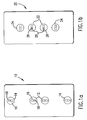
- FIG. 1a is a schematic diagram of an ADEPT having a pad that carries an endfire array 10.
- Two microwave receivers 12 are located between two microwave transmitters 14 with a spacing of 80 mm and 120 mm.
- the two receivers 12 and the two transmitters 14 are oriented vertically on the ADEPT, parallel to the longitudinal axis of the ADEPT and the borehole.
- Each receiver 12 and transmitter 14 comprises a rectangular slot antenna 16 having one probe element 18 perpendicular to the ADEPT and borehole axis.
- the endfire array 10 is less affected by hole roughness and tool standoff from mudcake than a conventional logging antenna system.
- the endfire array 10 has a good depth of investigation without sacrificing vertical resolution.
- the endfire array 10 is normally used when invaded zone resistivity is greater than 1 ohm-m.
- FIG. 1B is a schematic diagram of an ADEPT having a pad that carries a broadside array 20.
- Two microwave receivers 22 are located between two microwave transmitters 24 with a spacing of 40 mm and 80 mm.
- the two receivers 22 and the two transmitters 24 are oriented horizontally on the ADEPT, perpendicular to the longitudinal axis of the ADEPT and the borehole.
- Each receiver 22 and transmitter 24 comprises a rectangular slot antenna 26 having one probe element 28 parallel to the ADEPT and borehole axis.
- the short spacing between the receivers 22 and the transmitters 24 extends the effective operating range in high porosity or saline conditions, which increase attenuation of signals between such receivers and transmitters.
- the broadside array 20 has less depth of investigation than the endfire array 20, but has a sharper image response.
- the broadside array 20 is normally used in the ADEPT when invaded zone resistivity is less than 1 ohm/m.
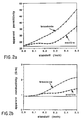
- Figures 2a and 2b illustrate the simulated standoff response of the endfire array 10 of Figure 1a and the broadside array 20 of Figure 1B at 1.1 GHz.
- formation conductivity is 0.9 S/m and formation permittivity is 22.
- Standoff layer conductivity is 4.0 S/m and standoff layer permittivity is 73.
- Figure 2a illustrates inverted permittivity as a function of standoff of the array, endfire or broadside, from the borehole wall in inches.
- Figure 2b illustrates inverted conductivity in mho/m as a function of standoff in inches.
- the endfire array of Figure 1a has better standoff performance than the broadside array.
- a solid, horizontal line indicates ideal standoff response.
- Figures 2a and 2b show that the standoff response of the endfire array is more nearly horizontal, and thus more closely approximates the ideal case than the standoff response of the broadside array. Standoff performance of the endfire array is typically good for standoff distances to 0.25 ⁇ .
- U. S. Patent No. 4,704,581 also assigned to the same assignee as this invention and incorporated by reference, describes a logging device having transmitters and receivers that comprise slot antennas.
- Each slot antenna includes a probe that extends across the cavity-backed antenna parallel to the longitudinal axis of the logging device in one embodiment, or extends across the cavity-backed antenna perpendicular to the longitudinal axis of the logging device in another embodiment.
- None of the above devices concerns a slot antenna having two elements which are energized to produce an electronically adjustable angle of magnetic moment.
- the invention concerns a slot antenna comprising an aperture and two non-parallel elements within the aperture. Each element is adapted to receive a corresponding current such that the slot antenna produces a magnetic moment having an orientation that depends on the two corresponding currents.
- the magnetic moment of the antenna is adjustable within the plane of the aperture by adjusting the magnitude and/or phase of the currents of the elements, and includes the case in which the current of one element is zero. This adjustment of the antenna's magnetic moment can be achieved with either hardware or software, the latter approach being the more flexible, allowing a much wider range of selectable magnetic moments to be achieved.
- An object of the invention is to provide an antenna which has a selectable magnetic moment.
- Another object of the invention is to provide an antenna that can alternately generate substantially perpendicular magnetic fields.
- Another object of the invention is to provide an array of antennas in an electromagnetic propagation tool, the magnetic moments of which are capable of being electronically adjusted.
- the electromagnetic propagation tool functions as both an endfire array having better standoff performance and a broadside array having a sharper image response without reconfiguring the tool.
- Figures 1a and 1b are schematic diagrams of a logging tool having an endfire array of antennas and a broadside array of antennas, respectively.
- Figures 2a and 2b illustrate the standoff response of the endfire array and the broadside array.
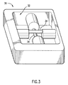
- Figure 3 is a perspective view of a cross-dipole slot antenna according to this invention.
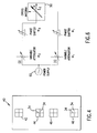
- Figure 4 is a schematic diagram of an array of cross-dipole antennas according to this invention.
- FIGS 5a-c are schematic diagrams of an antenna according to this invention which generates an adjustable magnetic moment.
- Figure 6 is a circuit for adjusting the magnetic moment of the cross-dipole antenna.
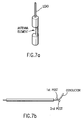
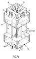
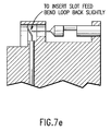
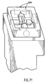
- Figures 7a-f illustrate a technique of making the slot antenna of Figure 3.
- Figures 8a-9b illustrate a comparison of dipole arrays to cross-dipole arrays.
- Figures 10a-13b compare actual boundaries to detected boundaries of a bed.
- FIG 3 shows a perspective view of a cross-dipole antenna 30 according to this invention.
- the antenna 30 is a slot antenna having a square aperture 32.
- the antenna 30 operates in the range of 200 to 2000 MHz and the antenna aperture is 0.334 ⁇ on each side.
- the antenna 30 has two perpendicular probe elements 34 which are centered in the aperture.
- Each probe element 34 is 0.063 ⁇ diameter at its opposite ends. The center of each probe is narrowed so the probes do not contact one another.
- Antennas of other dimensions are possible. These particular dimensions are one example and were chosen to yield an antenna having reasonable signal strength and acceptable resolution for borehole applications.
- the elements 34 could be off-centered, if desired. The technique of making such an antenna 30 is discussed below concerning Figures 7a to 7f.
- the two probe elements 34 are not perpendicular.
- the two probe elements 34 can be positioned at an angle relative to one another, in a range of angles which extends from 15 to 90 degrees, for example.
- the two probe elements 34 could be at any angle relative to one another as long as they are not parallel.
- Perpendicular probe elements are preferred for balanced electronics, but cannot be manufactured precisely. Thus, after the probe elements are assembled, even if they are substantially perpendicular, one must verify angles of magnetic moment using the formula discussed below concerning Figure 6. Software could be used to compensate for any discrepancy between an expected angle of magnetic moment and a measured angle.
- Figure 4 is a schematic diagram of an array 40 of cross-dipole antennas for use on an electromagnetic propagation tool.
- the antenna array 40 can be electronically switched to produce a vertical magnetic moment like an endfire array, and then a horizontal magnetic moment like a broadside array.
- the antenna array 40 can also be controlled electronically to adjust an angle of magnetic moment by simultaneously exciting the two elements of the antenna with currents of different amplitude and/or phase.
- the array 40 has been tested from 200 to 2000 MHz.
- the array 40 includes a first transmitter antenna 42 and a first receiver 44 spaced 45 mm from the first transmitter antenna 42.
- the array also includes a second receiver antenna 46 spaced 60 mm from the first transmitter antenna 42.
- a second transmitter antenna 48 is spaced symmetrically with respect to the first transmitter antenna 42: 45 mm from the second receiver antenna 46 and 60 mm from the first receiver antenna 44.
- the second transmitter antenna 48 provides a borehole-compensated measurement in a manner similar to the EPT.
- the spacings between transmitters and receivers can be varied. This spacing is chosen to determine depth of investigation and vertical resolution.
- Figures 5a-5c are schematic diagrams of the cross-dipole antenna 50 of this invention.
- Figure 5a only the horizontal element of the antenna 50 has been excited, resulting in a vertical magnetic moment.
- Figure 5b only the vertical element of the antenna 50 has been excited, resulting in a horizontal magnetic moment.
- Figure 5c both the horizontal element and the vertical element have been excited by equal signals to those elements, resulting in a 45-degree magnetic moment.
- Such a magnetic moment is one example of those that are achievable with the cross-dipole antenna of this invention.
- the magnetic moment of the antenna is electronically adjustable within the plane of the aperture by adjusting the magnitude and/or phase of the currents of the elements, and includes the case in which the current of one element is zero.
- the array of such dipole antennas 50 provides both better standoff performance and sharper imaging.
- a logging tool having an array of cross-dipole antennas is placed a desired depth in the borehole and the cross-dipole antennas are excited.
- a circuit, described below, changes the phase and amplitude of signals to the horizontal and vertical elements, to adjust the magnetic moment of the antenna through all angles between and including vertical and horizontal relative to the axis of the borehole. Regardless of the dip angle of the bed being logged, the magnetic moment at one adjustable angle is parallel to the borehole axis, which provides better standoff performance.
- the magnetic moment at another adjustable angle of the scan is perpendicular to the bed, which provides sharper imaging. This can be done with either hardware or software. The latter is more flexible and provides a wider range of selectable angles of scan.
- the array of dipole antennas 50 is used to broadcast in an endfire mode and broadside mode either simultaneously or sequentially.
- the two channels comprising elements 34 of each antenna are excited by slightly different frequencies.
- the vertical elements of antennas in an array 50 can be excited at 1.03 GHz, and the horizontal elements of those same antennas can be excited simultaneously at 1.00 GHz.
- These slightly different frequencies are equivalent from a rock physics viewpoint, but allow encoding of the simultaneously broadcast endfire and broadside modes.
- the image data from another logging tool such as a formation microscanner (FMS, mark of Schlumberger) tool, is processed to reconstruct a response by the antenna array which is parallel and perpendicular to the formation bed.
- FMS formation microscanner
- Figure 6 is a circuit for adjusting the angle of magnetic moment of the cross-dipole antenna 50 of Figure 5c.
- the signal from a signal source 60 is divided equally between the two paths (1) and (2).
- the current supplied to each path is denoted by I .
- the current undergoes an attenuation a1 and a phase shift f1 .
- the current undergoes an independent attenuation a2 and a phase shift f2 .
- I d I [(a1)2 + (a2)2] 1 ⁇ 2
- tan q (a1/a2)e i(f 1-f2)
- the current can then be continuously swept, or incrementally stepped, by varying the ratio a1/a2 from 0 to any arbitrarily large number.
- Such circuits are known, but have not been used to steer or adjust the magnetic moment of a cross-dipole slot antenna.
- Micro-Coax's coaxial cable #UT-47 in its straight length form (not coiled). Measure and cut all slot feed lengths identically, 1.00 ⁇ leaving center conductors long at both ends. Pre-extrude the dielectric of the slot feeds by placing in oven at 100°C for one hour. Polish the outer conductor with fine steel wool. Strip the dielectric even with the outer conductor at both ends. Cut one end of the center conductor to .050 ⁇ for acceptance into an Omni-Spectra Company's OSMM FM connector. Form an element lead joint loop at the other end by bending the center conductor against a first post and then against a second post. See Figure 7b. Cut off any excess.
- Step 1 start by pouring a drop of epoxy against the inner top surface of the lead channel. Let this epoxy settle to the bottom, forcing air out the bottom and along the inner bottom surface of the channel.
- Step 2 continue by pouring a drop or two of epoxy in the same manner.
- Step 3 when this has settled, finish by filling "lead joint well" completely. When potting is complete, there should be a convex surface over the lead joint well. This will allow for shrinkage after curing. Let cure. The convex surface will later be milled so that the upper hatch plug will fit correctly. Remove the teflon tape dam. Clean the area of the teflon tape dam making sure that there is no residual mastic left from the tape and inspect.
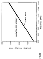
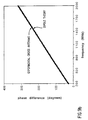
- Figures 8a to 9b illustrate a very close correlation between the response of a dipole model of an endfire array and the response of an array of cross-dipole antennas in 1 ohm.m of water.
- the dipole model and the cross-dipole antennas are compared to establish whether or not response of the cross-dipole antennas is affected by cross coupling between perpendicular antenna elements. Spacing between a transmitter of the endfire array and a receiver in a first location was 45 mm, and spacing between that transmitter and the receiver in a second location was 60 mm.
- Figure 8a shows amplitude ratio in dB
- Figure 8b shows phase difference in degrees, as a function of frequency in MHz.
- FIGS. 9a to 9b illustrate the homogeneous medium response of a broadside array, which has been arranged under the same constraints as the endfire array, described above. Again, only one of the two perpendicular elements has been excited.
- the curve of solid symbols represents the calculated response of the dipole model.
- the curve of hollow symbols represents the response of the experimental antennas.
- the figures clearly show that the response of the experimental antennas, each having one energized element and another unenergized perpendicular element, very closely tracks the response of the dipole model having single element antennas. It is evident from this comparison that any cross coupling between the energized element and the unenergized perpendicular element has a negligible effect on the the response of an endfire array that comprises antennas having two such elements.
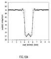
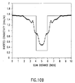
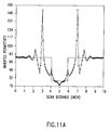
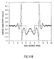
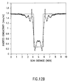
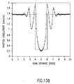
- Figures 10a to 13b show a comparison of actual boundaries of a bed to detected boundaries of the bed.
- the array comprises antennas having two perpendicular probe elements according to this invention.
- the figures illustrate the results of array scans of a 2-inch bed formation sandwiched between thick water beds at 1.0 GHz. Permittivity of the thick water beds is 74 and conductivity is 4.2 mho/m. Permittivity of the formation bed is 22 and conductivity is 0.9 mho/m. The spacing between a transmitter and a first receiver is 45 mm, and spacing between that same transmitter and a second receiver is 60 mm.
- Figures 10a, 11a, 12a, and 13a illustrate inverted permittivity as a function of scan distance in inches.
- Figures 10b, 11b, 12b, and 13b illustrate inverted conductivity in mho/m as a function of scan distance in inches.
- a solid line indicates the actual delineation of a bed boundary, while the points connected by a curve represents an approximation of the bed boundary based on detected permittivity or conductivity values. These values are produced as an array is scanned past the bed.
- the close correlation between the solid line and the curve indicates that the antenna of this invention readily identifies bed boundaries of a formation independent of any cross coupling that might occur between the two elements.
- Figures 10a to 10b illustrate the results of a scan of an endfire array when the axis of the array is perpendicular to the bed formation (a "vertical” scan) and Figures 11a to 11b illustrate the results of a scan of an endfire array when the axis of the array is parallel to the bed formation (a "horizontal” scan).
- a vertical scan illustrates the results of a scan of an endfire array when the axis of the array is perpendicular to the bed formation
- Figures 11a to 11b illustrate the results of a scan of an endfire array when the axis of the array is parallel to the bed formation
- Figures 12a to 12b illustrate results of a vertical scan of a broadside array and Figures 13a to 13b illustrate results of a horizontal scan of a broadside array.
- only the vertical element of each antenna is energized by a current and the antenna produces a magnetic moment having only a horizontal component.
- the inventors have demonstrated the performance of an antenna having a square aperture.
- the conclusions can be generalized to include an antenna having rectangular, elliptical, or circular apertures, for example.
Landscapes
- Life Sciences & Earth Sciences (AREA)
- Physics & Mathematics (AREA)
- General Physics & Mathematics (AREA)
- Geophysics (AREA)
- Environmental & Geological Engineering (AREA)
- Geology (AREA)
- Remote Sensing (AREA)
- General Life Sciences & Earth Sciences (AREA)
- Electromagnetism (AREA)
- Engineering & Computer Science (AREA)
- Geophysics And Detection Of Objects (AREA)
- Variable-Direction Aerials And Aerial Arrays (AREA)
- Details Of Aerials (AREA)
- Waveguide Aerials (AREA)
- Treatment Of Fiber Materials (AREA)
- Radar Systems Or Details Thereof (AREA)
Applications Claiming Priority (2)
| Application Number | Priority Date | Filing Date | Title |
|---|---|---|---|
| US70645491A | 1991-05-28 | 1991-05-28 | |
| US706454 | 1991-05-28 |
Publications (2)
| Publication Number | Publication Date |
|---|---|
| EP0516525A1 true EP0516525A1 (de) | 1992-12-02 |
| EP0516525B1 EP0516525B1 (de) | 2003-03-05 |
Family
ID=24837639
Family Applications (1)
| Application Number | Title | Priority Date | Filing Date |
|---|---|---|---|
| EP92401430A Expired - Lifetime EP0516525B1 (de) | 1991-05-28 | 1992-05-26 | Schlitzantenne mit zwei nichtparallelen Elementen |
Country Status (14)
| Country | Link |
|---|---|
| US (2) | US5243290A (de) |
| EP (1) | EP0516525B1 (de) |
| JP (1) | JP3280415B2 (de) |
| AT (1) | ATE233961T1 (de) |
| AU (1) | AU654346B2 (de) |
| BR (1) | BR9201956A (de) |
| DE (1) | DE69232939D1 (de) |
| DZ (1) | DZ1583A1 (de) |
| EG (1) | EG19615A (de) |
| MX (1) | MX9202420A (de) |
| MY (1) | MY108329A (de) |
| NO (1) | NO308924B1 (de) |
| OA (1) | OA09610A (de) |
| TN (1) | TNSN92039A1 (de) |
Cited By (6)
| Publication number | Priority date | Publication date | Assignee | Title |
|---|---|---|---|---|
| US5691734A (en) * | 1994-06-01 | 1997-11-25 | Alan Dick & Company Limited | Dual polarizating antennae |
| GB2430264A (en) * | 2005-09-12 | 2007-03-21 | Schlumberger Holdings | Determining properties of earth formations using dielectric permittivity measurements at a plurality of frequencies |
| WO2009089519A1 (en) * | 2008-01-11 | 2009-07-16 | Baker Hughes Incorporated | Method for building multi-component electromagnetic antennas |
| GB2458959A (en) * | 2008-04-04 | 2009-10-07 | Ohm Ltd | Electromagnetic surveying using a crossed electric dipole transmitter with selectable orientations |
| CN103558642A (zh) * | 2013-11-12 | 2014-02-05 | 中国电子科技集团公司第二十二研究所 | 天线装置 |
| US8786287B2 (en) | 2009-03-04 | 2014-07-22 | Baker Hughes Incorporated | Collocated tri-axial induction sensors with segmented horizontal coils |
Families Citing this family (49)
| Publication number | Priority date | Publication date | Assignee | Title |
|---|---|---|---|---|
| US5210495A (en) * | 1991-05-28 | 1993-05-11 | Schlumberger Technology Corp. | Electromagnetic logging method and apparatus with scanned magnetic dipole direction |
| FR2692931B1 (fr) * | 1992-06-25 | 1994-09-30 | Schlumberger Services Petrol | Procédé pour l'étude morphologique de formations géologiques traversées par un forage. |
| US5485743A (en) | 1994-09-23 | 1996-01-23 | Schlumberger Technology Corporation | Microwave device and method for measuring multiphase flows |
| US6163155A (en) * | 1999-01-28 | 2000-12-19 | Dresser Industries, Inc. | Electromagnetic wave resistivity tool having a tilted antenna for determining the horizontal and vertical resistivities and relative dip angle in anisotropic earth formations |
| US7659722B2 (en) * | 1999-01-28 | 2010-02-09 | Halliburton Energy Services, Inc. | Method for azimuthal resistivity measurement and bed boundary detection |
| US6703837B1 (en) * | 2000-09-15 | 2004-03-09 | Precision Drilling Technology Services Group, Inc. | Wellbore resistivity tool with simultaneous multiple frequencies |
| EP1331359B1 (de) * | 2002-01-29 | 2005-11-23 | Ingenjörsfirman Geotech Ab | Sondierungsvorrichtung mit Mikrowellenübertragung |
| US6806839B2 (en) * | 2002-12-02 | 2004-10-19 | Bae Systems Information And Electronic Systems Integration Inc. | Wide bandwidth flat panel antenna array |
| US7382135B2 (en) * | 2003-05-22 | 2008-06-03 | Schlumberger Technology Corporation | Directional electromagnetic wave resistivity apparatus and method |
| US7284605B2 (en) * | 2004-09-28 | 2007-10-23 | Schlumberger Technology Corporation | Apparatus and methods for reducing stand-off effects of a downhole tool |
| US7669668B2 (en) * | 2004-12-01 | 2010-03-02 | Schlumberger Technology Corporation | System, apparatus, and method of conducting measurements of a borehole |
| US7348781B2 (en) * | 2004-12-31 | 2008-03-25 | Schlumberger Technology Corporation | Apparatus for electromagnetic logging of a formation |
| EP1693685B1 (de) * | 2005-02-22 | 2014-10-22 | Services Petroliers Schlumberger | Elektromagnetische Sonde |
| GB2430493B (en) * | 2005-09-23 | 2008-04-23 | Schlumberger Holdings | Systems and methods for measuring multiphase flow in a hydrocarbon transporting pipeline |
| CN101501297B (zh) | 2006-07-11 | 2013-10-16 | 哈里伯顿能源服务公司 | 模块化地质导向工具组件 |
| WO2008008346A2 (en) * | 2006-07-12 | 2008-01-17 | Halliburton Energy Services, Inc. | Method and apparatus for building a tilted antenna |
| US8593147B2 (en) | 2006-08-08 | 2013-11-26 | Halliburton Energy Services, Inc. | Resistivity logging with reduced dip artifacts |
| AU2007295028B2 (en) * | 2006-09-13 | 2011-12-15 | Exxonmobil Upstream Research Company | Rapid inversion of electromagnetic reconnaissance survey data |
| EP1901094A1 (de) * | 2006-09-15 | 2008-03-19 | Services Pétroliers Schlumberger | Antenne für eine elektromagnetische Sonde zur Untersuchung von geologischen Formationen und ihren Anwendungen |
| US8274289B2 (en) | 2006-12-15 | 2012-09-25 | Halliburton Energy Services, Inc. | Antenna coupling component measurement tool having rotating antenna configuration |
| US7437251B2 (en) * | 2007-01-16 | 2008-10-14 | Baker Hughes Incorporated | Correction of sensor non-equipotentiality in a resistivity imaging device |
| US8014963B2 (en) * | 2007-01-16 | 2011-09-06 | Baker Hughes Incorporated | Correction of sensor non-equipotentiality in a resistivity imaging device |
| US8378908B2 (en) * | 2007-03-12 | 2013-02-19 | Precision Energy Services, Inc. | Array antenna for measurement-while-drilling |
| BRPI0711465B1 (pt) | 2007-03-16 | 2018-04-24 | Halliburton Energy Services, Inc. | ferramenta de perfilagem, e, método para ferramenta de perfilagem de resistividade azimutalmente sensível |
| EP1983357A1 (de) * | 2007-04-16 | 2008-10-22 | Services Pétroliers Schlumberger | Antenne für eine elektromagnetische Sonde zur Untersuchung geologischer Formationen |
| US7660671B2 (en) * | 2007-12-06 | 2010-02-09 | Schlumberger Technology Corporation | Method and apparatus for electromagnetic logging of a formation |
| US8547783B2 (en) * | 2007-12-12 | 2013-10-01 | Exxonmobil Upstream Research Company | Method and apparatus for evaluating submarine formations |
| AU2008348131B2 (en) | 2008-01-18 | 2011-08-04 | Halliburton Energy Services, Inc. | EM-guided drilling relative to an existing borehole |
| US8347985B2 (en) * | 2008-04-25 | 2013-01-08 | Halliburton Energy Services, Inc. | Mulitmodal geosteering systems and methods |
| AU2008365630B2 (en) * | 2008-12-16 | 2012-05-03 | Halliburton Energy Services, Inc. | Azimuthal at-bit resistivity and geosteering methods and systems |
| AU2010343292B2 (en) | 2010-01-22 | 2014-10-16 | Halliburton Energy Services Inc. | Method and apparatus for resistivity measurements |
| US8536883B2 (en) | 2010-04-29 | 2013-09-17 | Schlumberger Technology Corporation | Method of measuring a multiphase flow |
| CA2802722C (en) | 2010-07-27 | 2023-04-04 | Exxonmobil Upstream Research Company | Inverting geophysical data for geological parameters or lithology |
| EP2606452A4 (de) | 2010-08-16 | 2017-08-16 | Exxonmobil Upstream Research Company | Reduzierung der dimensionalität des joint-inversion-problems |
| EP2715603A4 (de) | 2011-06-02 | 2016-07-13 | Exxonmobil Upstream Res Co | Joint-inversion mit unbekannter lithologie |
| EP2721478A4 (de) | 2011-06-17 | 2015-12-02 | Exxonmobil Upstream Res Co | Einfrieren von domänen in einer verbindungsinversion |
| US9494711B2 (en) | 2011-07-21 | 2016-11-15 | Garrett M Leahy | Adaptive weighting of geophysical data types in joint inversion |
| WO2013072844A1 (en) | 2011-11-14 | 2013-05-23 | Schlumberger Technology B.V. | Enhanced materials investigation |
| EP2836860A4 (de) | 2012-06-25 | 2015-11-11 | Halliburton Energy Services Inc | Kippantennenmesssysteme und verfahren zur erzeugung von robusten messsignalen |
| TWM446984U (zh) * | 2012-08-01 | 2013-02-11 | Sj Antenna Design | 多頻天線裝置 |
| US10591638B2 (en) | 2013-03-06 | 2020-03-17 | Exxonmobil Upstream Research Company | Inversion of geophysical data on computer system having parallel processors |
| US9846255B2 (en) | 2013-04-22 | 2017-12-19 | Exxonmobil Upstream Research Company | Reverse semi-airborne electromagnetic prospecting |
| WO2016077011A1 (en) | 2014-11-10 | 2016-05-19 | General Electric Company | Multi-phase fluid fraction measurement |
| US10309910B2 (en) | 2014-11-10 | 2019-06-04 | General Electric Company | System and method to measure salinity of multi-phase fluids |
| US10725196B2 (en) | 2015-04-29 | 2020-07-28 | Halliburton Energy Services, Inc. | Bi-mode high frequency dielectric tool |
| US10948621B2 (en) | 2015-11-13 | 2021-03-16 | Halliburton Energy Services, Inc. | Microstrip antenna-based logging tool and method |
| US10935687B2 (en) | 2016-02-23 | 2021-03-02 | Halliburton Energy Services, Inc. | Formation imaging with electronic beam steering |
| US11137515B2 (en) | 2016-12-30 | 2021-10-05 | Halliburton Energy Services, Inc. | Time-domain broadband dielectric logging |
| US11788402B2 (en) * | 2019-07-08 | 2023-10-17 | Schlumberger Technology Corporation | Methods for determining a volume fraction of water and water salinity in organic shale reservoirs using multi-frequency dielectric well logging measurements |
Citations (8)
| Publication number | Priority date | Publication date | Assignee | Title |
|---|---|---|---|---|
| US3458862A (en) * | 1966-08-08 | 1969-07-29 | Esl Inc | Quadruply ridged waveguide and horn antenna |
| US3553703A (en) * | 1968-03-14 | 1971-01-05 | Univ Ohio State Res Found | Dual-mode super-directive slot antenna |
| US3740754A (en) * | 1972-05-24 | 1973-06-19 | Gte Sylvania Inc | Broadband cup-dipole and cup-turnstile antennas |
| US4052662A (en) * | 1973-08-23 | 1977-10-04 | Schlumberger Technology Corporation | Method and apparatus for investigating earth formations utilizing microwave electromagnetic energy |
| US4097869A (en) * | 1977-03-14 | 1978-06-27 | Stanford Research Institute | Orthogonal-port, biconical-horn, direction-finder antenna |
| EP0186570A2 (de) * | 1984-12-28 | 1986-07-02 | Schlumberger Limited | Gerät zur elektromagnetischen Untersuchung in einem Bohrloch mit Schlitzantennen |
| US4704581A (en) * | 1985-12-28 | 1987-11-03 | Schlumberger Technology Corp. | Electromagnetic logging apparatus using vertical magnetic dipole slot antennas |
| EP0437364A2 (de) * | 1990-01-10 | 1991-07-17 | Halliburton Logging Services, Inc. | Verfahren zur Trennung der refraktierten von reflektierten elektromagnetischen Signalen in elektromagnetischen Bohrlochmessgeräten |
Family Cites Families (12)
| Publication number | Priority date | Publication date | Assignee | Title |
|---|---|---|---|---|
| US2790138A (en) * | 1955-08-09 | 1957-04-23 | Schlumberger Well Surv Corp | Induction well logging |
| US3286163A (en) | 1963-01-23 | 1966-11-15 | Chevron Res | Method for mapping a salt dome at depth by measuring the travel time of electromagnetic energy emitted from a borehole drilled within the salt dome |
| US3978485A (en) * | 1965-05-25 | 1976-08-31 | Telecommunications Radioelectriques Et Telephoniques T.R.T. | Directional slot antenna for very high frequencies |
| US3653052A (en) * | 1970-09-18 | 1972-03-28 | Nasa | Omnidirectional slot antenna for mounting on cylindrical space vehicle |
| GB1364941A (en) * | 1972-01-05 | 1974-08-29 | Secr Defence | Aerials |
| US3944910A (en) * | 1973-08-23 | 1976-03-16 | Schlumberger Technology Corporation | Method and apparatus utilizing microwave electromagnetic energy for investigating earth formations |
| SU648928A1 (ru) * | 1973-08-31 | 1979-02-25 | Трест "Татнефтегеофизика" | Способ выделени трещинных коллекторов |
| US4063250A (en) * | 1975-12-16 | 1977-12-13 | Electrospace Systems, Inc. | Beam and null switch step steerable antenna system |
| US4360777A (en) * | 1979-12-31 | 1982-11-23 | Schlumberger Technology Corporation | Induction dipmeter apparatus and method |
| US4451789A (en) * | 1981-09-28 | 1984-05-29 | Nl Industries, Inc. | Logging tool and method for measuring resistivity of different radial zones at a common depth of measurement |
| US4636731A (en) * | 1984-12-31 | 1987-01-13 | Texaco Inc. | Propagation anisotropic well logging system and method |
| FR2592233B1 (fr) * | 1985-12-20 | 1988-02-12 | Radiotechnique Compelec | Antenne plane hyperfrequences recevant simultanement deux polarisations. |
-
1992
- 1992-05-01 AU AU15944/92A patent/AU654346B2/en not_active Expired
- 1992-05-20 DZ DZ920054A patent/DZ1583A1/fr active
- 1992-05-21 MX MX9202420A patent/MX9202420A/es unknown
- 1992-05-21 EG EG26992A patent/EG19615A/xx active
- 1992-05-21 MY MYPI92000866A patent/MY108329A/en unknown
- 1992-05-22 OA OA60212A patent/OA09610A/en unknown
- 1992-05-25 BR BR929201956A patent/BR9201956A/pt not_active IP Right Cessation
- 1992-05-26 DE DE69232939T patent/DE69232939D1/de not_active Expired - Lifetime
- 1992-05-26 AT AT92401430T patent/ATE233961T1/de not_active IP Right Cessation
- 1992-05-26 EP EP92401430A patent/EP0516525B1/de not_active Expired - Lifetime
- 1992-05-27 NO NO922123A patent/NO308924B1/no not_active IP Right Cessation
- 1992-05-28 JP JP13727392A patent/JP3280415B2/ja not_active Expired - Lifetime
- 1992-05-28 TN TNTNSN92039A patent/TNSN92039A1/fr unknown
-
1993
- 1993-01-06 US US08/000,916 patent/US5243290A/en not_active Expired - Lifetime
- 1993-07-27 US US08/098,018 patent/US5406206A/en not_active Expired - Lifetime
Patent Citations (8)
| Publication number | Priority date | Publication date | Assignee | Title |
|---|---|---|---|---|
| US3458862A (en) * | 1966-08-08 | 1969-07-29 | Esl Inc | Quadruply ridged waveguide and horn antenna |
| US3553703A (en) * | 1968-03-14 | 1971-01-05 | Univ Ohio State Res Found | Dual-mode super-directive slot antenna |
| US3740754A (en) * | 1972-05-24 | 1973-06-19 | Gte Sylvania Inc | Broadband cup-dipole and cup-turnstile antennas |
| US4052662A (en) * | 1973-08-23 | 1977-10-04 | Schlumberger Technology Corporation | Method and apparatus for investigating earth formations utilizing microwave electromagnetic energy |
| US4097869A (en) * | 1977-03-14 | 1978-06-27 | Stanford Research Institute | Orthogonal-port, biconical-horn, direction-finder antenna |
| EP0186570A2 (de) * | 1984-12-28 | 1986-07-02 | Schlumberger Limited | Gerät zur elektromagnetischen Untersuchung in einem Bohrloch mit Schlitzantennen |
| US4704581A (en) * | 1985-12-28 | 1987-11-03 | Schlumberger Technology Corp. | Electromagnetic logging apparatus using vertical magnetic dipole slot antennas |
| EP0437364A2 (de) * | 1990-01-10 | 1991-07-17 | Halliburton Logging Services, Inc. | Verfahren zur Trennung der refraktierten von reflektierten elektromagnetischen Signalen in elektromagnetischen Bohrlochmessgeräten |
Cited By (16)
| Publication number | Priority date | Publication date | Assignee | Title |
|---|---|---|---|---|
| US5691734A (en) * | 1994-06-01 | 1997-11-25 | Alan Dick & Company Limited | Dual polarizating antennae |
| GB2430264A (en) * | 2005-09-12 | 2007-03-21 | Schlumberger Holdings | Determining properties of earth formations using dielectric permittivity measurements at a plurality of frequencies |
| GB2430265A (en) * | 2005-09-12 | 2007-03-21 | Schlumberger Holdings | Determining properties of earth formations using dielectric permittivity and conductivity measurements |
| US7363160B2 (en) | 2005-09-12 | 2008-04-22 | Schlumberger Technology Corporation | Technique for determining properties of earth formations using dielectric permittivity measurements |
| US7376514B2 (en) | 2005-09-12 | 2008-05-20 | Schlumberger Technology Corporation | Method for determining properties of earth formations using dielectric permittivity measurements |
| GB2430265B (en) * | 2005-09-12 | 2008-06-25 | Schlumberger Holdings | Technique for determining properties of earth formations using dielectric permittivity measurements |
| GB2430264B (en) * | 2005-09-12 | 2008-06-25 | Schlumberger Holdings | Method for determining properties of earth formations using dielectric permittivity measurements |
| GB2468616B (en) * | 2008-01-11 | 2012-02-29 | Baker Hughes Inc | Method for building multi-component electromagnetic antennas |
| GB2468616A (en) * | 2008-01-11 | 2010-09-15 | Baker Hughes Inc | Method for building multi-component electromagnetic antennas |
| US7839149B2 (en) | 2008-01-11 | 2010-11-23 | Baker Hughes Incorporated | Multi-component resistivity logging tool with multiple antennas using common antenna grooves |
| WO2009089519A1 (en) * | 2008-01-11 | 2009-07-16 | Baker Hughes Incorporated | Method for building multi-component electromagnetic antennas |
| NO343448B1 (no) * | 2008-01-11 | 2019-03-11 | Baker Hughes A Ge Co Llc | Anordning og fremgangsmåte for å evaluere en grunnformasjon |
| GB2458959A (en) * | 2008-04-04 | 2009-10-07 | Ohm Ltd | Electromagnetic surveying using a crossed electric dipole transmitter with selectable orientations |
| GB2458959B (en) * | 2008-04-04 | 2010-08-18 | Ohm Ltd | electromagnetic surveying |
| US8786287B2 (en) | 2009-03-04 | 2014-07-22 | Baker Hughes Incorporated | Collocated tri-axial induction sensors with segmented horizontal coils |
| CN103558642A (zh) * | 2013-11-12 | 2014-02-05 | 中国电子科技集团公司第二十二研究所 | 天线装置 |
Also Published As
| Publication number | Publication date |
|---|---|
| EP0516525B1 (de) | 2003-03-05 |
| OA09610A (en) | 1993-04-30 |
| US5243290A (en) | 1993-09-07 |
| US5406206A (en) | 1995-04-11 |
| NO922123D0 (no) | 1992-05-27 |
| BR9201956A (pt) | 1993-01-12 |
| NO922123L (no) | 1992-11-30 |
| JPH06207984A (ja) | 1994-07-26 |
| EG19615A (en) | 1995-09-30 |
| DE69232939D1 (de) | 2003-04-10 |
| NO308924B1 (no) | 2000-11-13 |
| ATE233961T1 (de) | 2003-03-15 |
| MY108329A (en) | 1996-09-30 |
| DZ1583A1 (fr) | 2002-02-17 |
| MX9202420A (es) | 1992-11-01 |
| JP3280415B2 (ja) | 2002-05-13 |
| TNSN92039A1 (fr) | 1993-06-08 |
| AU1594492A (en) | 1992-11-26 |
| AU654346B2 (en) | 1994-11-03 |
Similar Documents
| Publication | Publication Date | Title |
|---|---|---|
| US5243290A (en) | Apparatus and method of logging using slot antenna having two nonparallel elements | |
| EP0648342B1 (de) | Verfahren und vorrichtung zum kalibrieren eines elektromagnetischen bohrlochmessgeräts während des bohrens | |
| CA1183207A (en) | Apparatus and method for improved electromagnetic logging in boreholes | |
| US5434507A (en) | Method and apparatus for electromagnetic logging with two dimensional antenna array | |
| US9599741B2 (en) | Antenna of an electromagnetic probe for investigating geological formations | |
| US6624634B2 (en) | Borehole current correction methods and apparatus | |
| CN101889217B (zh) | 用于对地层进行电磁测井的方法和设备 | |
| RU2377608C2 (ru) | Глубинные электромагнитные измерения с использованием скрещенных магнитных диполей | |
| US7066282B2 (en) | Apparatus and methods for measuring formation characteristics in presence of conductive and non-conductive muds | |
| US4697190A (en) | Borehole located directional antennae means for electromagnetic sensing systems | |
| MX2007010161A (es) | Una sonda electromagnetica. | |
| AU7190800A (en) | Method and apparatus for directional well logging | |
| WO2008031505A1 (en) | An antenna for an electromagnetic probe for investigating geological formations and its applications | |
| EP2005344B1 (de) | Biaxiales pad zur messung der resistivität von formationen | |
| CA1226329A (en) | Microwave electromagnetic borehole dipmeter | |
| GB2156527A (en) | Aperture antenna system for measurement of formation parameters | |
| CA2521456C (en) | Method and apparatus for measuring mud resistivity | |
| CA1227537A (en) | Microwave electromagnetic borehole dipmeter | |
| NO172086B (no) | Apparat for mikro-induktiv undersoekelse av grunnformasjoner |
Legal Events
| Date | Code | Title | Description |
|---|---|---|---|
| PUAI | Public reference made under article 153(3) epc to a published international application that has entered the european phase |
Free format text: ORIGINAL CODE: 0009012 |
|
| AK | Designated contracting states |
Kind code of ref document: A1 Designated state(s): AT DE DK FR GB IT NL |
|
| 17P | Request for examination filed |
Effective date: 19930423 |
|
| 17Q | First examination report despatched |
Effective date: 19950314 |
|
| GRAH | Despatch of communication of intention to grant a patent |
Free format text: ORIGINAL CODE: EPIDOS IGRA |
|
| GRAH | Despatch of communication of intention to grant a patent |
Free format text: ORIGINAL CODE: EPIDOS IGRA |
|
| GRAA | (expected) grant |
Free format text: ORIGINAL CODE: 0009210 |
|
| AK | Designated contracting states |
Designated state(s): AT DE DK FR GB IT NL |
|
| PG25 | Lapsed in a contracting state [announced via postgrant information from national office to epo] |
Ref country code: FR Free format text: LAPSE BECAUSE OF NON-PAYMENT OF DUE FEES Effective date: 20030305 Ref country code: AT Free format text: LAPSE BECAUSE OF FAILURE TO SUBMIT A TRANSLATION OF THE DESCRIPTION OR TO PAY THE FEE WITHIN THE PRESCRIBED TIME-LIMIT Effective date: 20030305 |
|
| REG | Reference to a national code |
Ref country code: GB Ref legal event code: FG4D |
|
| REF | Corresponds to: |
Ref document number: 69232939 Country of ref document: DE Date of ref document: 20030410 Kind code of ref document: P |
|
| PGFP | Annual fee paid to national office [announced via postgrant information from national office to epo] |
Ref country code: NL Payment date: 20030530 Year of fee payment: 12 |
|
| PG25 | Lapsed in a contracting state [announced via postgrant information from national office to epo] |
Ref country code: DK Free format text: LAPSE BECAUSE OF FAILURE TO SUBMIT A TRANSLATION OF THE DESCRIPTION OR TO PAY THE FEE WITHIN THE PRESCRIBED TIME-LIMIT Effective date: 20030605 |
|
| PG25 | Lapsed in a contracting state [announced via postgrant information from national office to epo] |
Ref country code: DE Free format text: LAPSE BECAUSE OF FAILURE TO SUBMIT A TRANSLATION OF THE DESCRIPTION OR TO PAY THE FEE WITHIN THE PRESCRIBED TIME-LIMIT Effective date: 20030606 |
|
| PLBE | No opposition filed within time limit |
Free format text: ORIGINAL CODE: 0009261 |
|
| STAA | Information on the status of an ep patent application or granted ep patent |
Free format text: STATUS: NO OPPOSITION FILED WITHIN TIME LIMIT |
|
| EN | Fr: translation not filed | ||
| 26N | No opposition filed |
Effective date: 20031208 |
|
| PG25 | Lapsed in a contracting state [announced via postgrant information from national office to epo] |
Ref country code: NL Free format text: LAPSE BECAUSE OF NON-PAYMENT OF DUE FEES Effective date: 20041201 |
|
| NLV4 | Nl: lapsed or anulled due to non-payment of the annual fee |
Effective date: 20041201 |
|
| PG25 | Lapsed in a contracting state [announced via postgrant information from national office to epo] |
Ref country code: IT Free format text: LAPSE BECAUSE OF NON-PAYMENT OF DUE FEES;WARNING: LAPSES OF ITALIAN PATENTS WITH EFFECTIVE DATE BEFORE 2007 MAY HAVE OCCURRED AT ANY TIME BEFORE 2007. THE CORRECT EFFECTIVE DATE MAY BE DIFFERENT FROM THE ONE RECORDED. Effective date: 20050526 |
|
| PGFP | Annual fee paid to national office [announced via postgrant information from national office to epo] |
Ref country code: GB Payment date: 20110525 Year of fee payment: 20 |
|
| REG | Reference to a national code |
Ref country code: GB Ref legal event code: PE20 Expiry date: 20120525 |
|
| PG25 | Lapsed in a contracting state [announced via postgrant information from national office to epo] |
Ref country code: GB Free format text: LAPSE BECAUSE OF EXPIRATION OF PROTECTION Effective date: 20120525 |