EP0516823B1 - Appareil servant a former des images, comprenant une cartouche remplacable et un systeme de nettoyage de l'element de transfert - Google Patents
Appareil servant a former des images, comprenant une cartouche remplacable et un systeme de nettoyage de l'element de transfert Download PDFInfo
- Publication number
- EP0516823B1 EP0516823B1 EP92903301A EP92903301A EP0516823B1 EP 0516823 B1 EP0516823 B1 EP 0516823B1 EP 92903301 A EP92903301 A EP 92903301A EP 92903301 A EP92903301 A EP 92903301A EP 0516823 B1 EP0516823 B1 EP 0516823B1
- Authority
- EP
- European Patent Office
- Prior art keywords
- image
- cleaning
- cartridge
- transfer member
- forming apparatus
- Prior art date
- Legal status (The legal status is an assumption and is not a legal conclusion. Google has not performed a legal analysis and makes no representation as to the accuracy of the status listed.)
- Expired - Lifetime
Links
Images

Classifications
-
- G—PHYSICS
- G03—PHOTOGRAPHY; CINEMATOGRAPHY; ANALOGOUS TECHNIQUES USING WAVES OTHER THAN OPTICAL WAVES; ELECTROGRAPHY; HOLOGRAPHY
- G03G—ELECTROGRAPHY; ELECTROPHOTOGRAPHY; MAGNETOGRAPHY
- G03G15/00—Apparatus for electrographic processes using a charge pattern
- G03G15/14—Apparatus for electrographic processes using a charge pattern for transferring a pattern to a second base
- G03G15/16—Apparatus for electrographic processes using a charge pattern for transferring a pattern to a second base of a toner pattern, e.g. a powder pattern, e.g. magnetic transfer
- G03G15/1605—Apparatus for electrographic processes using a charge pattern for transferring a pattern to a second base of a toner pattern, e.g. a powder pattern, e.g. magnetic transfer using at least one intermediate support
- G03G15/161—Apparatus for electrographic processes using a charge pattern for transferring a pattern to a second base of a toner pattern, e.g. a powder pattern, e.g. magnetic transfer using at least one intermediate support with means for handling the intermediate support, e.g. heating, cleaning, coating with a transfer agent
-
- G—PHYSICS
- G03—PHOTOGRAPHY; CINEMATOGRAPHY; ANALOGOUS TECHNIQUES USING WAVES OTHER THAN OPTICAL WAVES; ELECTROGRAPHY; HOLOGRAPHY
- G03G—ELECTROGRAPHY; ELECTROPHOTOGRAPHY; MAGNETOGRAPHY
- G03G15/00—Apparatus for electrographic processes using a charge pattern
- G03G15/01—Apparatus for electrographic processes using a charge pattern for producing multicoloured copies
- G03G15/0105—Details of unit
- G03G15/0131—Details of unit for transferring a pattern to a second base
-
- G—PHYSICS
- G03—PHOTOGRAPHY; CINEMATOGRAPHY; ANALOGOUS TECHNIQUES USING WAVES OTHER THAN OPTICAL WAVES; ELECTROGRAPHY; HOLOGRAPHY
- G03G—ELECTROGRAPHY; ELECTROPHOTOGRAPHY; MAGNETOGRAPHY
- G03G2215/00—Apparatus for electrophotographic processes
- G03G2215/01—Apparatus for electrophotographic processes for producing multicoloured copies
- G03G2215/0167—Apparatus for electrophotographic processes for producing multicoloured copies single electrographic recording member
- G03G2215/0174—Apparatus for electrophotographic processes for producing multicoloured copies single electrographic recording member plural rotations of recording member to produce multicoloured copy
- G03G2215/018—Linearly moving set of developing units, one at a time adjacent the recording member
-
- G—PHYSICS
- G03—PHOTOGRAPHY; CINEMATOGRAPHY; ANALOGOUS TECHNIQUES USING WAVES OTHER THAN OPTICAL WAVES; ELECTROGRAPHY; HOLOGRAPHY
- G03G—ELECTROGRAPHY; ELECTROPHOTOGRAPHY; MAGNETOGRAPHY
- G03G2215/00—Apparatus for electrophotographic processes
- G03G2215/16—Transferring device, details
- G03G2215/1647—Cleaning of transfer member
- G03G2215/1657—Cleaning of transfer member of transfer drum
-
- G—PHYSICS
- G03—PHOTOGRAPHY; CINEMATOGRAPHY; ANALOGOUS TECHNIQUES USING WAVES OTHER THAN OPTICAL WAVES; ELECTROGRAPHY; HOLOGRAPHY
- G03G—ELECTROGRAPHY; ELECTROPHOTOGRAPHY; MAGNETOGRAPHY
- G03G2221/00—Processes not provided for by group G03G2215/00, e.g. cleaning or residual charge elimination
- G03G2221/16—Mechanical means for facilitating the maintenance of the apparatus, e.g. modular arrangements and complete machine concepts
- G03G2221/1603—Mechanical means for facilitating the maintenance of the apparatus, e.g. modular arrangements and complete machine concepts for multicoloured copies
-
- G—PHYSICS
- G03—PHOTOGRAPHY; CINEMATOGRAPHY; ANALOGOUS TECHNIQUES USING WAVES OTHER THAN OPTICAL WAVES; ELECTROGRAPHY; HOLOGRAPHY
- G03G—ELECTROGRAPHY; ELECTROPHOTOGRAPHY; MAGNETOGRAPHY
- G03G2221/00—Processes not provided for by group G03G2215/00, e.g. cleaning or residual charge elimination
- G03G2221/16—Mechanical means for facilitating the maintenance of the apparatus, e.g. modular arrangements and complete machine concepts
- G03G2221/1618—Mechanical means for facilitating the maintenance of the apparatus, e.g. modular arrangements and complete machine concepts for the cleaning unit
-
- G—PHYSICS
- G03—PHOTOGRAPHY; CINEMATOGRAPHY; ANALOGOUS TECHNIQUES USING WAVES OTHER THAN OPTICAL WAVES; ELECTROGRAPHY; HOLOGRAPHY
- G03G—ELECTROGRAPHY; ELECTROPHOTOGRAPHY; MAGNETOGRAPHY
- G03G2221/00—Processes not provided for by group G03G2215/00, e.g. cleaning or residual charge elimination
- G03G2221/16—Mechanical means for facilitating the maintenance of the apparatus, e.g. modular arrangements and complete machine concepts
- G03G2221/1642—Mechanical means for facilitating the maintenance of the apparatus, e.g. modular arrangements and complete machine concepts for the transfer unit
-
- G—PHYSICS
- G03—PHOTOGRAPHY; CINEMATOGRAPHY; ANALOGOUS TECHNIQUES USING WAVES OTHER THAN OPTICAL WAVES; ELECTROGRAPHY; HOLOGRAPHY
- G03G—ELECTROGRAPHY; ELECTROPHOTOGRAPHY; MAGNETOGRAPHY
- G03G2221/00—Processes not provided for by group G03G2215/00, e.g. cleaning or residual charge elimination
- G03G2221/16—Mechanical means for facilitating the maintenance of the apparatus, e.g. modular arrangements and complete machine concepts
- G03G2221/1651—Mechanical means for facilitating the maintenance of the apparatus, e.g. modular arrangements and complete machine concepts for connecting the different parts
-
- G—PHYSICS
- G03—PHOTOGRAPHY; CINEMATOGRAPHY; ANALOGOUS TECHNIQUES USING WAVES OTHER THAN OPTICAL WAVES; ELECTROGRAPHY; HOLOGRAPHY
- G03G—ELECTROGRAPHY; ELECTROPHOTOGRAPHY; MAGNETOGRAPHY
- G03G2221/00—Processes not provided for by group G03G2215/00, e.g. cleaning or residual charge elimination
- G03G2221/16—Mechanical means for facilitating the maintenance of the apparatus, e.g. modular arrangements and complete machine concepts
- G03G2221/18—Cartridge systems
- G03G2221/183—Process cartridge
Definitions
- This invention relates to image-forming apparatus of the type which includes a replaceable cartridge, for example, a cartridge containing a photoconductive drum. It also relates to image-forming apparatus which includes an endless transfer member, for example, a transfer drum, which transfer member must be cleaned.
- U.S. Patent 3,847,119, Hoffman et al, issued November 12, 1974, is typical of a large number of references showing a transfer drum or roller for assisting in transfer of a toner image to a receiving sheet from a photoconductive image member.
- the transfer roller is continuously cleaned by a fur brush and the particles of toners so cleaned are removed by a vacuum source.
- U.S. Patent 4,026,648, Takahashi, issued May 31, 1977 showing a blade cleaner for a transfer roller.
- U.S. Patent 4,453,820, Suzuki, issued June 12, 1984 is representative of a number of references which show an intermediate transfer member to which a toner image is transferred from the original image member, and from which the toner image is then transferred directly to a receiving sheet. Unless transfer to the receiving sheet is 100% effective, the surface of such a transfer member must be cleaned before a new toner image is transferred to it. See also, Bothner, U.S. 4,712,906, issued December 15, 1987.
- U.S. 4,876,577, Ogura et al, issued October 24, 1989 is representative of a number of references which show an image-forming unit into which a cartridge is loaded.
- the cartridge includes a photoconductive drum, a blade cleaning device for the drum, a charger and access to the drum for both toning and transfer of images.
- Including the cleaning device for the photoconductive as part of the cartridge eliminates the need for operator disposal of residual toner cleaned off the photoconductive drum.
- the residual toner left in the cartridge can be disposed of or recycled when the cartridge is returned to the factory for recycling of the photoconductive drum.
- U.S. Patent 4,862,224 granted to Ku, on August 29, 1989, shows a roller cleaning device for a transfer drum.
- the cleaning roller is made of a material attractive to toner and is biased relative to the transfer drum to create an electric field attracting toner to the cleaning roller.
- the roller is articulatable in and out of contact with the transfer drum so that the apparatus can superpose a plurality of single color images on a receiving sheet carried by the transfer drum to make a multicolor image.
- a blade is spring-biased against the cleaning roller to clean toner off of the roller into a container associated with the roller. The container is either emptied or replaced periodically.
- JP-A-59 220 756 discloses a subchassis supporting a photoconductive drum member, an intermediate transfer member and a transfer member cleaning means, said subchassis serving for precisely positioning said members and means relative to each other and with respect to the main chassis of an image reproducing apparatus into which the subchassis is insertable. Neither is the subchassis in the form of a cartridge, nor does it feature means for collecting toner cleaned off the surface of any of said members or members forming part of the main chassis.
- an image-forming apparatus of the type which includes a transfer member according to claim 1 and an insertable cartridge according to claim 11.
- a replaceable cartridge for example, one containing an image member, is supplied to the apparatus.
- the replaceable cartridge also includes a sump for receiving such toner.
- the transfer drum is cleaned by an articulating cleaning mechanism which is permanent in the image-forming apparatus and the cartridge includes a chamber for receiving toner cleaned off by that cleaning mechanism which chamber includes an opening which is positioned directly below the cleaning mechanism.
- the cartridge not only includes an image member, it includes means for cleaning the transfer member as well as means for receiving and containing the residual toner cleaned from the transfer member.
- residual toner cleaned off the transfer member does not need to be separately disposed of in servicing the image-forming apparatus.
- the toner cleaned off the transfer member is returned to the factory for disposal or reuse when the image member is recycled.
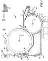
- Fig. 1 is a front schematic of an image-forming apparatus constructed according to the invention.
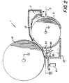
- Figs. 2 and 3 are front schematics similar to Fig. 1 illustrating alternative embodiments of the invention.
- image-forming apparatus for example, an electrophotographic printer 1 includes means 50 for receiving a cartridge 3.
- Cartridge 3 includes an image member, for example, photoconductive drum 2 journaled on its axis for rotation bringing its outer surface past a series of electrophotographic stations.
- Photoconductive drum 2 is first uniformly charged at a charging station 4 and imagewise exposed at an exposure station, for example, by a laser 5, through an opening in cartridge 3.
- Laser 5 is controlled to create a series of electrostatic images on the surface of drum 2 which electrostatic images correspond to color separations or highlight color components of a desired multicolor print.
- Development station 6 includes a plurality of development units which are sequentially positioned in development relation with the periphery of drum 2 to apply different color toners to each image of the series of electrostatic images.
- An opening 7 in cartridge 3 provides access to drum 2 for toning station 6.
- the different color toner images are transferred in registration to the cylindrical outside surface of a transfer drum 10.
- An opening 9 in cartridge 3 provides access to drum 2 for transfer drum 10.
- the transfer drum 10 and the photoconductive drum 2 can be driven by appropriate drive means, not shown, well known in the art and not part of this invention.
- a separate single color toner image is transferred in registration with the previous toner images to create a multicolor image on its periphery.
- the multicolor image is transferred at a conventional corona transfer station 21 (or, alternatively, a roller transfer station) to a receiving sheet fed from a receiving sheet supply 20.
- the receiving sheet is picked off the surface of transfer drum 10 by a sheet pick-off 22 which also guides the sheet to a fuser 23 and hence to an output tray, not shown.
- Photoconductive drum 2 is continuously cleaned by cleaning blade 12 with the toner collecting in a residual toner chamber 11 in cartridge 3.
- transfer drum 10 Unless transfer of toner to the receiving sheet at transfer station 21 is 100% complete, transfer drum 10 also needs to be cleaned. Accordingly, a cleaning roller 30 is positioned adjacent the surface of transfer drum 10. Because transfer drum 10 requires several revolutions to form a multicolor image, cleaning roller 30 is articulatable out of contact with transfer drum 10 by a solenoid 31 during image transfer and permitted to return under spring bias into cleaning contact with the transfer drum 10 after the multicolor image has been transferred at transfer station 21. During contact with transfer drum 10, toner is cleaned off drum 10 by a combination of choice of materials for cleaning roller 30 and an electric field urging toner to cleaning roller 30 which field is applied between cleaning roller 30 and drum 10. Toner is cleaned off cleaning roller 30 by a cleaning blade 32. For more details of a similar cleaning roller for a transfer drum, see U.S. Patent 4,862,224, to Ku, issued August 29, 1989.
- toner cleaned off the cleaning roller 30 is deposited in a sump which forms a housing for the cleaning roller. This sump must be emptied or replaced periodically which requires additional servicing.
- the Ku cleaning mechanism is designed to clean a transfer roller which holds a transfer sheet on its periphery. It therefore cleans considerably less toner from the surface of the transfer drum than is cleaned by cleaning roller 30 in Fig. 1.
- cartridge 3 includes a sump 35 having an opening 36 at its top which opening is positioned to receive toner cleaned off cleaning roller 30.
- opening 36 is positioned below the engagement of roller 30 with blade 32.
- Opening 36 can be provided with a cover, not shown, which is openable before insertion of cartridge 3 or as part of insertion of cartridge 3 in the printer 1. It can be spring biased to a closed position to which position it moves as the cartridge is removed. Alternatively, a tape can be provided to the operator for use when removing the cartridge, which tape is placed by the operator over opening 36.
- Figs. 2 and 3 show an alternative approach to cleaning transfer roller 10 which also provides a chamber 35 for receiving toner cleaned off transfer drum 10.
- the cleaning device is located within cartridge 3.
- the articulation mechanism is permanent in printer 1.
- cartridge 3 includes a cleaning roller 60 which is mounted on an elongated shaft 63 which is journaled in bearings which extend beyond cartridge 3. Shaft 63 is spring-urged into engagement with transfer drum 10. Cleaning roller 60 is articulated out of such contact by actuation of a pair of solenoids 61 which rotate lever 64 to engage and move the bearings for shaft 63 away from transfer drum 10 in opposition to its normal spring bias.
- rollers 30 and 60 are rotated by contact with the transfer drum 10 and do not need to be separately driven.
- rollers 30 and 60 should be biased to make rollers 30 and 60 more attractive to toner than to transfer drum 10.
- Transfer drum 10 is ordinarily biased with respect to photoconductive drum 2 to be more attractive to toner to enable transfer of the toner images to transfer drum 10.
- a still higher bias can be applied to cleaning rollers 30 or 60.
- transfer drum 10 can be grounded during cleaning, enabling cleaning with a lower bias supplied to rollers 30 and 60.
- FIG. 3 shows an alternative embodiment in which a bias is not necessary for cleaning.
- chamber 35 in cartridge 3 includes a cleaning web 70 which is trained from a supply roll 72 to a take-up roll 73 across a pressure roll 76.
- Cleaning web 70 is of a conventional cleaning web structure known in the art, for example, of cloth or paper.
- Supply roll 72 is continually biased by a rotary spring to maintain a slight amount of tension on web 70.
- Web 70 is indexed by gradual rotation of take-up roller 73 which is driven through a reduction gear train 74 from a drive roller 75 which engages the periphery of drum 2.
- drum 2 is driven by the printer, and drum 2 in turn drives roller 75 and take-up roller 73 to gradually index web 70.
- Web 70 is articulated into and out of contact with transfer drum 10 by a solenoid 71 which rotates a lever 79 in a clockwise direction to move pressure roller 76 against its spring urging and away from transfer drum 10 during multicolor image formation. Solenoid 71 is released for cleaning, during which the spring urging of pressure member 76 causes it to move to transfer drum 10 which then is contacted by web 70 for cleaning.
- Lever 79 is connected at both ends of roller 76 and pivots about a rod 78 which runs the length of the cartridge 3. Lever 79 terminates in a rod 77 which also runs the length of the cartridge 3 but is external to the cartridge for access to solenoid 71.
- the toner cleaned off the transfer member is collected within the cartridge and therefore does not require periodic removal. Instead, it is removed from the image-forming apparatus with the replacement of the cartridge itself.
- FIGs. show an apparatus in which single color toner images are transferred directly to the surface of the transfer drum 10, it is also known to place a receiving sheet on the drum 10.
- the receiving sheet is held by gripping fingers, vacuum or electrostatics.
- the receiving sheet is moved through transfer relation with photoconductive drum 2 repeatedly to superpose the toner images directly on it.
- the receiving sheet is then separated at a position remote from the position of transfer and fed to a fuser. With such structure it is still necessary to clean the surface of the transfer drum.
- This invention can be used with such apparatus. However, it has somewhat more utility with the apparatus shown in Figs. 1-3 because the amount of toner being cleaned is substantially greater when multicolor images are transferred directly to the surface of drum 10 rather than a receiving sheet attached to it.
- both image member 2 and transfer member 10 are shown as drums, it is also known to utilize endless webs for these two members and to include the image member as an endless web in a cartridge. Although the drums shown in the Figs. have some advantages over such structure, the invention can be used with an endless web as either or both image member and transfer member.
- the image-forming apparatus is shown as a printer 1 in the Figs. in which image formation is accomplished by a laser 5, it can also be any other device in which an image member is used to create toner images.
- electrostatic images could be created on the image member 2 by imagewise optical exposure or by imagewise ion deposition.
Landscapes
- Physics & Mathematics (AREA)
- General Physics & Mathematics (AREA)
- Cleaning In Electrography (AREA)
- Electrostatic Charge, Transfer And Separation In Electrography (AREA)
Abstract
Claims (16)
- Dispositif de formation d'image comprenant :un élément de formation d'image (2),un élément de transfert (10),des moyens (4, 5) pour créer une image électrostatique sur ledit élément de formation d'image,des moyens (6) pour charger de toner ladite image électrostatique afin de créer une image de toner,des moyens (21) pour transférer ladite image de toner à une surface associée audit élément de transfert,des moyens (30 ; 60 ; 70) pour nettoyer ledit élément de transfert de toner,caractérisé par une unique cartouche remplaçable (3), qui comprend à la fois ledit élément de formation d'image (2) et des moyens (35, 70) pour recevoir le toner nettoyé dudit élément de transfert (10).
- Dispositif de formation d'image selon la revendication 1, dans lequel ledit élément de transfert (10) comporte une surface périphérique destinée à recevoir une image de toner dudit élément de formation d'image (2) et ledit dispositif de formation d'image comprend des moyens (21) pour transférer une image de toner dudit élément de transfert à une feuille réceptrice.
- Dispositif de formation d'image selon la revendication 1, dans lequel ledit dispositif comprend des moyens (4, 5) pour former une série d'images électrostatiques sur ledit élément de formation d'image (2) et des moyens (6, 7) pour charger de toner chacune de ladite série d'images électrostatiques avec des toners de couleurs différentes et dans lequel lesdits moyens (21) pour transférer comprennent des moyens pour transférer lesdites images de toner en repérage à ladite surface associée audit élément de transfert afin de créer une image multicolore.
- Dispositif de formation d'image selon la revendication 2, dans lequel lesdits moyens (4, 5) pour créer une image électrostatique comprennent des moyens pour créer une série d'images électrostatiques et lesdits moyens (6, 7) pour charger de toner lesdites images électrostatiques comprennent des moyens pour appliquer du toner de différentes couleurs à chacune desdites images de ladite série, et lesdits moyens pour transférer comprennent des moyens pour transférer lesdites images de toner de couleurs différentes à la surface dudit élément de transfert afin de créer une image de toner multicolore sur la surface dudit élément de transfert et dans lequel ledit dispositif de formation d'image comprend en outre des moyens (21) pour transférer ladite image multicolore à une feuille réceptrice.
- Dispositif de formation d'image selon la revendication 1, dans lequel lesdits moyens de nettoyage (30 ; 60 ; 70) sont une partie permanente dudit dispositif de formation d'image et ladite cartouche comprend une chambre avec une ouverture (36) destinée à recevoir le toner nettoyé par lesdits moyens de nettoyage.
- Dispositif de formation d'image selon la revendication 5, dans lequel lesdits moyens de nettoyage comprennent un rouleau de nettoyage (30 ; 60 ; 76), pouvant être amené en contact de roulement avec ledit élément de transfert (10) et une lame de nettoyage (32 ; 62) touchant ledit rouleau afin de nettoyer le toner dudit rouleau de nettoyage, et dans lequel ladite ouverture (36) est immédiatement au-dessous de la position de contact de ladite lame (32) et dudit rouleau de nettoyage (30 ; 60).
- Dispositif de formation d'image selon la revendication 1, dans lequel lesdits moyens de nettoyage (30 ; 60 ; 70) sont montés dans ladite cartouche (3).
- Dispositif de formation d'image selon la revendication 7, dans lequel lesdits moyens de nettoyage (30 ; 60 ; 70) sont un rouleau de nettoyage (30 ; 60 ; 76), monté sur un arbre (63), lequel arbre s'étend à l'extérieur de ladite cartouche (3) et dans lequel ledit dispositif de formation d'image comprend des moyens (31 ; 61, 64 ; 71, 77, 79) pour déplacer ledit arbre afin de déplacer ledit rouleau entre des positions en et hors de contact avec ledit élément de transfert (10).
- Dispositif de formation d'image selon la revendication 7, dans lequel lesdits moyens de nettoyage sont une bande de nettoyage (70) montée dans ladite cartouche (3) et pouvant être amenée en et hors de contact avec ledit élément de transfert (10).
- Dispositif de formation d'image selon la revendication 7, dans lequel lesdits moyens de nettoyage sont une bande de nettoyage (70) et ladite cartouche comprend une réserve et des moyens d'enroulement (73, 72) de ladite bande, et dans lequel ladite cartouche comprend en outre des moyens (74, 75) associés audit élément de formation d'image (2) pour faire tourner lesdits moyens d'enroulement (73) en réponse au déplacement dudit élément de formation d'image (2).
- Cartouche (3) insérable dans un dispositif de formation d'image, lequel dispositif de formation d'image comprend un élément de transfert (10) et des moyens (30 ; 60 ; 70) pour nettoyer ledit élément de transfert, et comprenant :un élément de formation d'image (2) présentant une surface sur laquelle peuvent être formées des images de toner,des moyens (9) définissant une ouverture dans ladite cartouche à travers laquelle lesdites images peuvent être transférées audit élément de transfert (10), ladite cartouche étant caractérisée par :des moyens (35) pour recevoir le toner nettoyé dudit élément de transfert par lesdits moyens de nettoyage.
- Cartouche selon la revendication 11, dans laquelle ladite cartouche comprend également des moyens (4) pour charger uniformément ledit élément de formation d'image (2) et des moyens pour nettoyer ledit élément de formation d'image.
- Cartouche selon la revendication 11, dans laquelle lesdits moyens pour recevoir du toner sont une chambre (35) comportant une ouverture (36) ménagée dans son dessus.
- Cartouche selon la revendication 11, comprenant : des moyens (60 ; 70, 76) pour nettoyer ledit élément de transfert (10).
- Cartouche selon la revendication 14, dans laquelle lesdits moyens de nettoyage sont un rouleau de nettoyage (60 ; 76) qui peut être amené en et hors de contact avec ledit élément de transfert (10).
- Cartouche selon la revendication 14, dans laquelle lesdits moyens de nettoyage sont une bande de nettoyage enroulable (70).
Applications Claiming Priority (3)
| Application Number | Priority Date | Filing Date | Title |
|---|---|---|---|
| US632710 | 1975-11-17 | ||
| US07/632,710 US5070370A (en) | 1990-12-24 | 1990-12-24 | Image-forming apparatus having a replaceable cartridge and a transfer member cleaning device |
| PCT/US1991/009491 WO1992011583A1 (fr) | 1990-12-24 | 1991-12-17 | Appareil servant a former des images, comprenant une cartouche remplaçable et un systeme de nettoyage de l'element de transfert |
Publications (2)
| Publication Number | Publication Date |
|---|---|
| EP0516823A1 EP0516823A1 (fr) | 1992-12-09 |
| EP0516823B1 true EP0516823B1 (fr) | 1996-04-03 |
Family
ID=24536615
Family Applications (1)
| Application Number | Title | Priority Date | Filing Date |
|---|---|---|---|
| EP92903301A Expired - Lifetime EP0516823B1 (fr) | 1990-12-24 | 1991-12-17 | Appareil servant a former des images, comprenant une cartouche remplacable et un systeme de nettoyage de l'element de transfert |
Country Status (5)
| Country | Link |
|---|---|
| US (1) | US5070370A (fr) |
| EP (1) | EP0516823B1 (fr) |
| JP (1) | JPH05505256A (fr) |
| DE (1) | DE69118521T2 (fr) |
| WO (1) | WO1992011583A1 (fr) |
Families Citing this family (11)
| Publication number | Priority date | Publication date | Assignee | Title |
|---|---|---|---|---|
| US5471284A (en) * | 1990-01-19 | 1995-11-28 | Canon Kabushiki Kaisha | Image forming apparatus having toner depletion detection feature |
| US5220386A (en) * | 1990-08-31 | 1993-06-15 | Canon Kabushiki Kaisha | Image forming apparatus having cleanable transfer material carrying means |
| DE69203807T2 (de) * | 1991-02-04 | 1996-03-21 | Eastman Kodak Co | Bilderzeugungsgerät und arbeitseinheit mit einem bildträgerelement. |
| US5291254A (en) * | 1991-04-18 | 1994-03-01 | Hitachi, Ltd. | Electrophotographic recording apparatus |
| EP0530491B1 (fr) * | 1991-08-02 | 1997-05-07 | Minolta Co., Ltd. | Appareil électrophotographique de formation d'images muni d'une unité de formation d'images amovible |
| JPH0553455A (ja) * | 1991-08-23 | 1993-03-05 | Toshiba Corp | 転写装置 |
| JPH0667508A (ja) * | 1991-11-22 | 1994-03-11 | Canon Inc | 画像形成装置及びプロセスカートリッジ |
| US5469247A (en) * | 1994-07-05 | 1995-11-21 | Lexmark International, Inc. | Toned member cleaning by electrified roller |
| KR100247983B1 (ko) * | 1997-08-27 | 2000-03-15 | 윤종용 | 습식전자사진방식프린터의전사롤러크리닝장치 |
| JP3859112B2 (ja) * | 2000-02-28 | 2006-12-20 | 株式会社リコー | 画像形成装置 |
| US7274902B2 (en) * | 2005-03-30 | 2007-09-25 | Hewlett-Packard Development Company, L.P. | Printer transfer member |
Family Cites Families (9)
| Publication number | Priority date | Publication date | Assignee | Title |
|---|---|---|---|---|
| US4026648A (en) * | 1971-12-17 | 1977-05-31 | Canon Kabushiki Kaisha | Cleaning device for use in electrophotographic copying apparatus |
| US3847119A (en) * | 1972-03-27 | 1974-11-12 | Xerox Corp | Transfer roller assembly |
| JPS55100582A (en) * | 1979-01-25 | 1980-07-31 | Ricoh Co Ltd | Toner image transferring method |
| JPS58190965A (ja) * | 1982-04-30 | 1983-11-08 | Canon Inc | 感光体ユニット及びこの感光体ユニットが着脱可能な画像形成装置 |
| JPS62156671A (ja) * | 1985-12-27 | 1987-07-11 | Sharp Corp | 画像形成装置のカ−トリツジ装置 |
| US4712906A (en) * | 1987-01-27 | 1987-12-15 | Eastman Kodak Company | Electrostatographic apparatus having a transfer drum |
| US4862224A (en) * | 1988-04-04 | 1989-08-29 | Eastman Kodak Company | Cleaning device for electrostatic imaging apparatus |
| US4891676A (en) * | 1988-05-17 | 1990-01-02 | Colorocs Corporation | Transfer medium cleaning station for use in an electrophotographic print engine |
| DE68913488D1 (de) * | 1988-12-27 | 1994-04-07 | Konishiroku Photo Ind | Farbbilderzeugungsgerät. |
-
1990
- 1990-12-24 US US07/632,710 patent/US5070370A/en not_active Expired - Fee Related
-
1991
- 1991-12-17 WO PCT/US1991/009491 patent/WO1992011583A1/fr not_active Ceased
- 1991-12-17 JP JP92503725A patent/JPH05505256A/ja active Pending
- 1991-12-17 DE DE69118521T patent/DE69118521T2/de not_active Expired - Fee Related
- 1991-12-17 EP EP92903301A patent/EP0516823B1/fr not_active Expired - Lifetime
Also Published As
| Publication number | Publication date |
|---|---|
| DE69118521T2 (de) | 1996-10-10 |
| JPH05505256A (ja) | 1993-08-05 |
| WO1992011583A1 (fr) | 1992-07-09 |
| DE69118521D1 (de) | 1996-05-09 |
| EP0516823A1 (fr) | 1992-12-09 |
| US5070370A (en) | 1991-12-03 |
Similar Documents
| Publication | Publication Date | Title |
|---|---|---|
| US4888620A (en) | Process cartridge and image forming apparatus using the same | |
| EP0407183B1 (fr) | Appareil de formation d'images en couleurs | |
| US5414493A (en) | Image forming apparatus | |
| US5606406A (en) | Process cartridge provided with an accurately positioned transfer roller | |
| US5070370A (en) | Image-forming apparatus having a replaceable cartridge and a transfer member cleaning device | |
| JPS6079368A (ja) | 画像記録装置 | |
| JP3398317B2 (ja) | カラー画像形成装置 | |
| JP3285741B2 (ja) | カラー画像形成装置及びプロセスカートリッジ | |
| JP3111605B2 (ja) | 電子写真装置 | |
| JPH04119363A (ja) | 画像形成装置 | |
| JP2004126156A (ja) | 画像形成装置 | |
| JP3588098B2 (ja) | 電子写真画像形成装置 | |
| US5079592A (en) | Cleaning system for electrophotographic apparatus | |
| JPH06317979A (ja) | 電子写真記録装置 | |
| JP3380531B2 (ja) | カラー画像記録装置 | |
| JP3036144B2 (ja) | 電子写真装置 | |
| JP3485902B2 (ja) | カラー画像記録装置 | |
| JPH11161046A (ja) | 画像形成装置 | |
| JP3372757B2 (ja) | 画像形成装置 | |
| JPH07199768A (ja) | 画像形成装置 | |
| JP3103541B2 (ja) | カラー画像記録装置とそれに用いる中間転写ベルトユニット | |
| JPS5824151A (ja) | 画像形成装置に着脱自在なプロセスキット | |
| EP0523235B1 (fr) | Dispositif d'impression d'image et element-cartouche d'elaboration d'image | |
| JP3133205B2 (ja) | カラー画像記録装置 | |
| JP3103542B2 (ja) | カラー画像記録装置とそれに用いる中間転写ベルトユニット |
Legal Events
| Date | Code | Title | Description |
|---|---|---|---|
| PUAI | Public reference made under article 153(3) epc to a published international application that has entered the european phase |
Free format text: ORIGINAL CODE: 0009012 |
|
| AK | Designated contracting states |
Kind code of ref document: A1 Designated state(s): DE FR GB NL |
|
| 17P | Request for examination filed |
Effective date: 19930107 |
|
| 17Q | First examination report despatched |
Effective date: 19940627 |
|
| RBV | Designated contracting states (corrected) |
Designated state(s): DE GB |
|
| GRAA | (expected) grant |
Free format text: ORIGINAL CODE: 0009210 |
|
| AK | Designated contracting states |
Kind code of ref document: B1 Designated state(s): DE GB |
|
| REF | Corresponds to: |
Ref document number: 69118521 Country of ref document: DE Date of ref document: 19960509 |
|
| PGFP | Annual fee paid to national office [announced via postgrant information from national office to epo] |
Ref country code: GB Payment date: 19961108 Year of fee payment: 6 |
|
| PGFP | Annual fee paid to national office [announced via postgrant information from national office to epo] |
Ref country code: DE Payment date: 19961227 Year of fee payment: 6 |
|
| PLBE | No opposition filed within time limit |
Free format text: ORIGINAL CODE: 0009261 |
|
| STAA | Information on the status of an ep patent application or granted ep patent |
Free format text: STATUS: NO OPPOSITION FILED WITHIN TIME LIMIT |
|
| 26N | No opposition filed | ||
| PG25 | Lapsed in a contracting state [announced via postgrant information from national office to epo] |
Ref country code: GB Free format text: LAPSE BECAUSE OF NON-PAYMENT OF DUE FEES Effective date: 19971217 |
|
| GBPC | Gb: european patent ceased through non-payment of renewal fee |
Effective date: 19971217 |
|
| PG25 | Lapsed in a contracting state [announced via postgrant information from national office to epo] |
Ref country code: DE Free format text: LAPSE BECAUSE OF NON-PAYMENT OF DUE FEES Effective date: 19980901 |