EP0517018B2 - Cabine de sécurité pour charger des propulseurs inflammables dans des conteneurs aérosols - Google Patents
Cabine de sécurité pour charger des propulseurs inflammables dans des conteneurs aérosols Download PDFInfo
- Publication number
- EP0517018B2 EP0517018B2 EP92108275A EP92108275A EP0517018B2 EP 0517018 B2 EP0517018 B2 EP 0517018B2 EP 92108275 A EP92108275 A EP 92108275A EP 92108275 A EP92108275 A EP 92108275A EP 0517018 B2 EP0517018 B2 EP 0517018B2
- Authority
- EP
- European Patent Office
- Prior art keywords
- cabin
- conveyor
- shield
- loading
- door
- Prior art date
- Legal status (The legal status is an assumption and is not a legal conclusion. Google has not performed a legal analysis and makes no representation as to the accuracy of the status listed.)
- Expired - Lifetime
Links
Images




Classifications
-
- B—PERFORMING OPERATIONS; TRANSPORTING
- B65—CONVEYING; PACKING; STORING; HANDLING THIN OR FILAMENTARY MATERIAL
- B65B—MACHINES, APPARATUS OR DEVICES FOR, OR METHODS OF, PACKAGING ARTICLES OR MATERIALS; UNPACKING
- B65B31/00—Packaging articles or materials under special atmospheric or gaseous conditions; Adding propellants to aerosol containers
- B65B31/003—Adding propellants in fluid form to aerosol containers
-
- F—MECHANICAL ENGINEERING; LIGHTING; HEATING; WEAPONS; BLASTING
- F17—STORING OR DISTRIBUTING GASES OR LIQUIDS
- F17C—VESSELS FOR CONTAINING OR STORING COMPRESSED, LIQUEFIED OR SOLIDIFIED GASES; FIXED-CAPACITY GAS-HOLDERS; FILLING VESSELS WITH, OR DISCHARGING FROM VESSELS, COMPRESSED, LIQUEFIED, OR SOLIDIFIED GASES
- F17C13/00—Details of vessels or of the filling or discharging of vessels
- F17C13/12—Arrangements or mounting of devices for preventing or minimising the effect of explosion ; Other safety measures
-
- F—MECHANICAL ENGINEERING; LIGHTING; HEATING; WEAPONS; BLASTING
- F17—STORING OR DISTRIBUTING GASES OR LIQUIDS
- F17C—VESSELS FOR CONTAINING OR STORING COMPRESSED, LIQUEFIED OR SOLIDIFIED GASES; FIXED-CAPACITY GAS-HOLDERS; FILLING VESSELS WITH, OR DISCHARGING FROM VESSELS, COMPRESSED, LIQUEFIED, OR SOLIDIFIED GASES
- F17C2201/00—Vessel construction, in particular geometry, arrangement or size
- F17C2201/03—Orientation
- F17C2201/032—Orientation with substantially vertical main axis
-
- F—MECHANICAL ENGINEERING; LIGHTING; HEATING; WEAPONS; BLASTING
- F17—STORING OR DISTRIBUTING GASES OR LIQUIDS
- F17C—VESSELS FOR CONTAINING OR STORING COMPRESSED, LIQUEFIED OR SOLIDIFIED GASES; FIXED-CAPACITY GAS-HOLDERS; FILLING VESSELS WITH, OR DISCHARGING FROM VESSELS, COMPRESSED, LIQUEFIED, OR SOLIDIFIED GASES
- F17C2201/00—Vessel construction, in particular geometry, arrangement or size
- F17C2201/05—Size
- F17C2201/058—Size portable (<30 l)
-
- F—MECHANICAL ENGINEERING; LIGHTING; HEATING; WEAPONS; BLASTING
- F17—STORING OR DISTRIBUTING GASES OR LIQUIDS
- F17C—VESSELS FOR CONTAINING OR STORING COMPRESSED, LIQUEFIED OR SOLIDIFIED GASES; FIXED-CAPACITY GAS-HOLDERS; FILLING VESSELS WITH, OR DISCHARGING FROM VESSELS, COMPRESSED, LIQUEFIED, OR SOLIDIFIED GASES
- F17C2221/00—Handled fluid, in particular type of fluid
- F17C2221/03—Mixtures
- F17C2221/032—Hydrocarbons
- F17C2221/035—Propane butane, e.g. LPG, GPL
-
- F—MECHANICAL ENGINEERING; LIGHTING; HEATING; WEAPONS; BLASTING
- F17—STORING OR DISTRIBUTING GASES OR LIQUIDS
- F17C—VESSELS FOR CONTAINING OR STORING COMPRESSED, LIQUEFIED OR SOLIDIFIED GASES; FIXED-CAPACITY GAS-HOLDERS; FILLING VESSELS WITH, OR DISCHARGING FROM VESSELS, COMPRESSED, LIQUEFIED, OR SOLIDIFIED GASES
- F17C2223/00—Handled fluid before transfer, i.e. state of fluid when stored in the vessel or before transfer from the vessel
- F17C2223/01—Handled fluid before transfer, i.e. state of fluid when stored in the vessel or before transfer from the vessel characterised by the phase
- F17C2223/0146—Two-phase
- F17C2223/0153—Liquefied gas, e.g. LPG, GPL
-
- F—MECHANICAL ENGINEERING; LIGHTING; HEATING; WEAPONS; BLASTING
- F17—STORING OR DISTRIBUTING GASES OR LIQUIDS
- F17C—VESSELS FOR CONTAINING OR STORING COMPRESSED, LIQUEFIED OR SOLIDIFIED GASES; FIXED-CAPACITY GAS-HOLDERS; FILLING VESSELS WITH, OR DISCHARGING FROM VESSELS, COMPRESSED, LIQUEFIED, OR SOLIDIFIED GASES
- F17C2223/00—Handled fluid before transfer, i.e. state of fluid when stored in the vessel or before transfer from the vessel
- F17C2223/03—Handled fluid before transfer, i.e. state of fluid when stored in the vessel or before transfer from the vessel characterised by the pressure level
- F17C2223/033—Small pressure, e.g. for liquefied gas
-
- F—MECHANICAL ENGINEERING; LIGHTING; HEATING; WEAPONS; BLASTING
- F17—STORING OR DISTRIBUTING GASES OR LIQUIDS
- F17C—VESSELS FOR CONTAINING OR STORING COMPRESSED, LIQUEFIED OR SOLIDIFIED GASES; FIXED-CAPACITY GAS-HOLDERS; FILLING VESSELS WITH, OR DISCHARGING FROM VESSELS, COMPRESSED, LIQUEFIED, OR SOLIDIFIED GASES
- F17C2227/00—Transfer of fluids, i.e. method or means for transferring the fluid; Heat exchange with the fluid
- F17C2227/04—Methods for emptying or filling
-
- F—MECHANICAL ENGINEERING; LIGHTING; HEATING; WEAPONS; BLASTING
- F17—STORING OR DISTRIBUTING GASES OR LIQUIDS
- F17C—VESSELS FOR CONTAINING OR STORING COMPRESSED, LIQUEFIED OR SOLIDIFIED GASES; FIXED-CAPACITY GAS-HOLDERS; FILLING VESSELS WITH, OR DISCHARGING FROM VESSELS, COMPRESSED, LIQUEFIED, OR SOLIDIFIED GASES
- F17C2270/00—Applications
- F17C2270/05—Applications for industrial use
- F17C2270/059—Mass bottling, e.g. merry belts
Definitions
- This invention relates to a safety cabin for loading flammable propellant, such as butane, into aerosol cans, said cabin containing conventional loading means with a loading head and being also traversed by a continuous can conveyor which cabin is more fully defined by the first part of claim 1.
- a usual solution is to load the flammable propellant in explosion-proof cabins. These cabins are located at a distance from the building without direct passage between the two.
- the positive side of this solution is that the dangerous part (cabin) is completely separated from the building in which the cans undergo other operations.
- the negative side is that this solution is costly, requires a remote monitoring system and involves production line maintenance, and any format change (requiring the production line to be adapted to the different can size or format) means that the operator has to leave the building and enter the cabin, which must therefore be of such a size as to allow him to operate about the means contained therein.
- An object of the present invention is to provide a cabin which although offering maximum safety is of compact size, is directly accessible from the production department without having to leave this latter, and enables the operation of the means situated within it to be directly viewed.
- a further object of the present invention is to provide a cabin to which access is conditional on the state of the environment within it.
- forced air streams are provided in such a manner that they strike the cans.
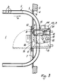
- the reference numeral 1 indicates the production department in which various conventional operations are performed on the cans B, and within which there extends a conveyor belt 2 by which the cans are conveyed.
- the production department is bounded towards the outside by a wall 3 in which there is provided a rectangular or square aperture 4 which is closed by a robust closure means 5, for example a steel plate 2-3 cm thick, secured in conventional manner to the surrounding of the aperture 4 and known hereinafter as the "shield".
- the shield 5 comprises a substantially rectangular aperture 8.
- a box structure of corresponding form is rigid with this aperture and projects slightly into the environment 1, for example by a few centimetres, whereas it projects considerably outwards.
- the box structure is closed on the side facing the environment 1 by a sealed armoured flameproof door 10 hinged at 11 along its vertical side to a robust metal frame 12 rigid with the shield 5.
- a lever 13 mounted on the door controls conventional bars 72 (see Figure 7) which enter seats 73 in the frame 12 to maintain the door closed, this being provided with perimetral seal means to seal against the edge of the box structure at that part thereof which projects into the environment 1.
- a sheet of armoured glass 14 is mounted in the door 10 to enable the interior of the box structure 9 to be viewed.
- the box structure 9 which forms the actual safety cabin in which the propellant is loaded into the cabins, is traversed by the conveyor 2 which extends through apertures or passageways 14 provided in the two side walls 15 of the box structure, these side walls being constructed, as are the floor 16 and roof 17, of metal plate of adequate thickness to support the operating means contained in said structure.
- the rear wall 18 of the structure 9 is formed from a transparent sheet of light material, preferably makrolon, hinged at 20 to the roof 17 of the structure and resting against the edges of the remaining walls which bound it.
- the hinging is such that if an explosion occurs in the cabin, the sheet is ejected.
- the relative technology is conventional.
- the piston has a rod 26 with its end rounded to act on the sheet 18.
- pneumatic pressure acts within the cylinder, the rod 26 withdraws into the cylinder 23 and the sheet moves by gravity into its closed position.
- this pressure is absent, the rod 26 emerges under the thrust of the spring 24 to rotate the sheet into its open position, to allow atmospheric air to enter the interior of the structure 9.
- pneumatic pressure is fed to this cylinder when sensors (described hereinafter) sense the presence of a given excess of propellant within the structure 9.
- sensors described hereinafter
- the use of transparent material for the movable wall 18 allows the contents of the box structure 9 to be illuminated naturally or artificially from the outside.
- the interior of the box structure 9 houses the following:
- suction ports 40 which, via ducts 41 within the structure 9, lead to a manifold 42 emerging from said structure and opening on the suction side of a centrifugal fan 43, the delivery side of which is connected to a discharge stack 44. This removes from the structure 9 any possible propellant losses.
- a first conventional propellant gas sensor (catalytic sensor) 50 which feeds its electrical output signal to a central control unit, not shown, which also receives the signal from a second gas sensor (catalytic sensor) 51 positioned on the opposite side of the structure 9 in its lower part.
- these sensors measure the propellant gas concentration and emit an electrical signal proportional to the measured concentration.
- the central control unit not forming part of the invention, compares the received signals and on the basis of these exercises control in the manner briefly described hereinafter.
- a device is provided at the passageways 6, 7 to partially close them.
- These devices consist of a guillotine shaped plate 60 which a spring 61 tends to maintain in the closed position, whereas a pneumatic cylinder 62 tends to maintain the plate in the open position.
- the guillotine plates are guided in vertical guides, not shown, provided on the outer face of the shield 5, to which the cylinder 62 is connected.
- the cans B are struck from above by streams of air (Figure 5) drawn from the environment 1 by the centrifugal fan 63 and fed via a distributor 64 connected to the fan delivery.
- Said air streams can also originate from air drawn from the outside of the environment 1 provided it is not contaminated with flammable gas.
- the mechanism for closing the door 10 is shown schematically in Figure 7.
- the lever 13 mounted rotatably on the door is rigid with an arm 70.
- the ends of the arm are hinged to linearly guided bars 72 which can engage seats 73 in the frame 12.
- a single acting pneumatic cylinder 74 on the piston 75 of which there acts a spring 76. If pneumatic pressure is absent the piston rod 77 lies below a tooth 77A on one of the bars and prevents door opening. If instead pressure is present, the door can be opened as the rod 77 has withdrawn into the cylinder.
- the door 10 is closed but can be opened because the rod 77 does not lie below the tooth 77A.
- the fans 43 and 63 are in operation, the movable wall 18 is in its closed position and the guillotine plates 60 are raised. If the propellant concentration increases just slightly the door can still be opened, but in this case pneumatic pressure to the cylinder 23 is shut off with the result that the movable wall 18 rotates into its open position under the thrust of the spring 24, and external air enters the cabin. If in spite of this the concentration still rises, pneumatic pressure is no longer fed to the cylinder 74 so that the door 10 cannot be opened, the guillotine plates 60 are lowered and production stops, whereas the fans remain in operation and the movable wall 18 remains open.
Landscapes
- Engineering & Computer Science (AREA)
- Mechanical Engineering (AREA)
- Chemical & Material Sciences (AREA)
- Dispersion Chemistry (AREA)
- General Engineering & Computer Science (AREA)
- Respiratory Apparatuses And Protective Means (AREA)
- Vacuum Packaging (AREA)
- Air-Conditioning For Vehicles (AREA)
- Automobile Manufacture Line, Endless Track Vehicle, Trailer (AREA)
- Filling Of Jars Or Cans And Processes For Cleaning And Sealing Jars (AREA)
Claims (3)
- Cabine de sécurité pour charger des gaz propulseurs inflammables dans des conteneurs aérosols (B), dotée de moyens de chargement classiques comprenant une tête de chargement (32) et traversée par un convoyeur de conteneurs (2) qui vient de - et va vers - un environnement de travail (1) en étant associé à un écran de protection (5) délimitant extérieurement ledit environnement de travail, et comprenant une porte d'accès (10) dirigée vers - et accessible depuis - ledit environnement de travail, et une paroi amovible (18) prévue extérieurement à l'opposé de la porte, et un système d'aspiration (42 - 44) comportant des ouïes d'aspiration (40) situées respectivement au niveau de la tête de chargement (32) et en partie basse de la cabine, et comprenant en outre un moyen de mesure de concentration en gaz propulseur (50) côté entrée du système d'aspiration, ainsi qu'un second moyen de mesure de concentration en gaz propulseur (51) en partie basse de la cabine, caractérisée en ce que des moyens (63, 64) sont prévus pour envoyer un flux d'air sur les conteneurs que transporte le convoyeur (2) le long de l'un au moins des passages empruntés par le convoyeur entre la cabine et l'écran (5).
- Cabine de sécurité selon la revendication 1, caractérisée en ce que des éléments commandés (60, 61, 62) sont prévus pour obturer l'entrée et la sortie du convoyeur à travers l'écran (5), en correspondance avec ladite entrée et ladite sortie.
- Cabine de sécurité selon l'une ou l'autre des revendications 1 et 2, caractérisée en ce que la paroi amovible (18) est montée sur des charnières et en ce qu'elle est actionnée par un élément de poussée rétractable par action pneumatique (21) commandé par l'un au moins des moyens de mesure de concentration en propulseur (50, 51), de façon à faire pivoter ladite paroi en position ouverte lorsqu'une concentration en propulseur donnée est atteinte dans la cabine.
Applications Claiming Priority (2)
| Application Number | Priority Date | Filing Date | Title |
|---|---|---|---|
| ITMI911569A IT1248006B (it) | 1991-06-07 | 1991-06-07 | Cabina di sicurezza per il caricamento di propellenti infiammabili in bombole per aerosol |
| ITMI911569 | 1991-06-07 |
Publications (3)
| Publication Number | Publication Date |
|---|---|
| EP0517018A1 EP0517018A1 (fr) | 1992-12-09 |
| EP0517018B1 EP0517018B1 (fr) | 1994-11-30 |
| EP0517018B2 true EP0517018B2 (fr) | 1997-10-29 |
Family
ID=11360065
Family Applications (1)
| Application Number | Title | Priority Date | Filing Date |
|---|---|---|---|
| EP92108275A Expired - Lifetime EP0517018B2 (fr) | 1991-06-07 | 1992-05-15 | Cabine de sécurité pour charger des propulseurs inflammables dans des conteneurs aérosols |
Country Status (5)
| Country | Link |
|---|---|
| US (1) | US5209273A (fr) |
| EP (1) | EP0517018B2 (fr) |
| DE (1) | DE69200743T3 (fr) |
| ES (1) | ES2065724T5 (fr) |
| IT (1) | IT1248006B (fr) |
Families Citing this family (9)
| Publication number | Priority date | Publication date | Assignee | Title |
|---|---|---|---|---|
| US7429262B2 (en) * | 1992-01-07 | 2008-09-30 | Arthrocare Corporation | Apparatus and methods for electrosurgical ablation and resection of target tissue |
| US5681282A (en) * | 1992-01-07 | 1997-10-28 | Arthrocare Corporation | Methods and apparatus for ablation of luminal tissues |
| US5404921A (en) * | 1994-03-31 | 1995-04-11 | American Bristol Industries, Inc. | Rotary fill station for breathing apparatus |
| US5797436A (en) * | 1995-06-26 | 1998-08-25 | Oden Corporation | Liquid filling machine technical field |
| FI990302A7 (fi) * | 1999-02-15 | 2000-08-16 | Juha Tapio Koskinen | Menetelmä ja sovitelma hitsaamotilojen ilmanvaihdon säätöä varten |
| JP2001346318A (ja) * | 2000-05-31 | 2001-12-14 | Mitsubishi Heavy Ind Ltd | 防爆施設への電線導入構造 |
| US7704249B2 (en) * | 2004-05-07 | 2010-04-27 | Arthrocare Corporation | Apparatus and methods for electrosurgical ablation and resection of target tissue |
| FR2874593B1 (fr) * | 2004-08-26 | 2006-11-17 | Fillon Investissement | Installation de remplissage de recipient aerosol |
| DE102014200452B4 (de) * | 2014-01-13 | 2025-03-27 | Hecht Technologie Gmbh | Entleerungseinrichtung |
Family Cites Families (5)
| Publication number | Priority date | Publication date | Assignee | Title |
|---|---|---|---|---|
| GB831756A (en) * | 1957-10-04 | 1960-03-30 | Calor Gas Distributing Company | Gas container-filling apparatus |
| US3259152A (en) * | 1963-01-31 | 1966-07-05 | Auto Prod Inc | Apparatus for filling and shaking a can |
| FR2034202B1 (fr) * | 1969-02-21 | 1976-10-01 | Primagaz | |
| US3817299A (en) * | 1972-04-10 | 1974-06-18 | C Koehler | Expansive gas protective device |
| CA1319920C (fr) * | 1988-10-07 | 1993-07-06 | Akira Suzuki | Systeme de remplissage et de recuperation de bouteilles pour agitateur rotatif |
-
1991
- 1991-06-07 IT ITMI911569A patent/IT1248006B/it active IP Right Grant
-
1992
- 1992-05-15 DE DE69200743T patent/DE69200743T3/de not_active Expired - Lifetime
- 1992-05-15 ES ES92108275T patent/ES2065724T5/es not_active Expired - Lifetime
- 1992-05-15 EP EP92108275A patent/EP0517018B2/fr not_active Expired - Lifetime
- 1992-06-05 US US07/893,780 patent/US5209273A/en not_active Expired - Lifetime
Also Published As
| Publication number | Publication date |
|---|---|
| EP0517018A1 (fr) | 1992-12-09 |
| ES2065724T5 (es) | 1998-03-16 |
| DE69200743T3 (de) | 1998-04-09 |
| ITMI911569A0 (it) | 1991-06-07 |
| EP0517018B1 (fr) | 1994-11-30 |
| DE69200743T2 (de) | 1995-04-06 |
| IT1248006B (it) | 1995-01-05 |
| ES2065724T3 (es) | 1995-02-16 |
| US5209273A (en) | 1993-05-11 |
| ITMI911569A1 (it) | 1992-12-07 |
| DE69200743D1 (de) | 1995-01-12 |
Similar Documents
| Publication | Publication Date | Title |
|---|---|---|
| EP0517018B2 (fr) | Cabine de sécurité pour charger des propulseurs inflammables dans des conteneurs aérosols | |
| CA2726897C (fr) | Appareil de transport de grains pneumatique, et procede de decharge selective des grains dans un elevateur a grains ou de derivation des grains dans un autre recipient | |
| US5651625A (en) | Printer enclosure and controller unit | |
| NO326869B1 (no) | Anlegg for beskikning av flere forbrukere, for eksempel celler av aluminiumssmelteovner med styrtgods, for eksempel pulverformet aluminiumoksid | |
| US3795084A (en) | Packaging apparatus | |
| US5970688A (en) | Apparatus for opening pouches for insertion of objects thereinto | |
| ES270735U (es) | Un silo de gran capacidad para el almacenaje y la homogeneizacion de materiales harinosos a granel. | |
| US4526097A (en) | Feed mechanism for apparatus for evacuating and compacting aerosol cans | |
| US5464162A (en) | Device for reducing paper, in particular valuable papers | |
| US20010001374A1 (en) | Apparatus for splitting articles | |
| EP3795933B1 (fr) | Dispositif de refroidissement comprenant un dispositif à vide | |
| EP1475128B1 (fr) | Dispositif de lutte contre l'incendie par gaz inerte et méthode de lutte contre l'incendie | |
| CN111678659A (zh) | 一种瓷柱式断路器检漏方法 | |
| CN109305548A (zh) | 新型伺服旋转分档式排料机构 | |
| US4140929A (en) | Air pressurizing system | |
| CN223761142U (zh) | 一种喂料器及破碎系统 | |
| CN112027361A (zh) | 一种多功能医用配药取用盒 | |
| US3908773A (en) | Devices for progressive throttling to complete shut-off of the discharge in machines for dispensing fluidizable material in weight portions | |
| GB2032272A (en) | Self-closing vents and ventilation system | |
| US5931276A (en) | Adjustable chute for x-ray sheet film | |
| CN220096757U (zh) | 一种自动化抽纸包装系统 | |
| KR200233855Y1 (ko) | 곡물의자동계량승강장치 | |
| US20260116592A1 (en) | Metering device for a packaging machine, packaging machine with such a metering device and method for operating a metering device | |
| US20230038086A1 (en) | System and method for suppression of smoke and/or fire in an auger system | |
| GB1431361A (en) | Bag filling machine having door-type inlet valve |
Legal Events
| Date | Code | Title | Description |
|---|---|---|---|
| PUAI | Public reference made under article 153(3) epc to a published international application that has entered the european phase |
Free format text: ORIGINAL CODE: 0009012 |
|
| AK | Designated contracting states |
Kind code of ref document: A1 Designated state(s): DE ES FR GB |
|
| 17P | Request for examination filed |
Effective date: 19921209 |
|
| 17Q | First examination report despatched |
Effective date: 19940422 |
|
| GRAA | (expected) grant |
Free format text: ORIGINAL CODE: 0009210 |
|
| AK | Designated contracting states |
Kind code of ref document: B1 Designated state(s): DE ES FR GB |
|
| REF | Corresponds to: |
Ref document number: 69200743 Country of ref document: DE Date of ref document: 19950112 |
|
| ET | Fr: translation filed | ||
| REG | Reference to a national code |
Ref country code: ES Ref legal event code: FG2A Ref document number: 2065724 Country of ref document: ES Kind code of ref document: T3 |
|
| PLBI | Opposition filed |
Free format text: ORIGINAL CODE: 0009260 |
|
| 26 | Opposition filed |
Opponent name: D.H. INDUSTRIES LIMITED; BWI KP AEROFILL LIMITED Effective date: 19950828 |
|
| PLBF | Reply of patent proprietor to notice(s) of opposition |
Free format text: ORIGINAL CODE: EPIDOS OBSO |
|
| PLAW | Interlocutory decision in opposition |
Free format text: ORIGINAL CODE: EPIDOS IDOP |
|
| PLAW | Interlocutory decision in opposition |
Free format text: ORIGINAL CODE: EPIDOS IDOP |
|
| PUAH | Patent maintained in amended form |
Free format text: ORIGINAL CODE: 0009272 |
|
| STAA | Information on the status of an ep patent application or granted ep patent |
Free format text: STATUS: PATENT MAINTAINED AS AMENDED |
|
| 27A | Patent maintained in amended form |
Effective date: 19971029 |
|
| AK | Designated contracting states |
Kind code of ref document: B2 Designated state(s): DE ES FR GB |
|
| ET3 | Fr: translation filed ** decision concerning opposition | ||
| REG | Reference to a national code |
Ref country code: ES Ref legal event code: DC2A Kind code of ref document: T5 Effective date: 19971230 |
|
| REG | Reference to a national code |
Ref country code: GB Ref legal event code: IF02 |
|
| PGFP | Annual fee paid to national office [announced via postgrant information from national office to epo] |
Ref country code: ES Payment date: 20110427 Year of fee payment: 20 Ref country code: FR Payment date: 20110616 Year of fee payment: 20 |
|
| PGFP | Annual fee paid to national office [announced via postgrant information from national office to epo] |
Ref country code: GB Payment date: 20110527 Year of fee payment: 20 |
|
| PGFP | Annual fee paid to national office [announced via postgrant information from national office to epo] |
Ref country code: DE Payment date: 20110518 Year of fee payment: 20 |
|
| REG | Reference to a national code |
Ref country code: DE Ref legal event code: R071 Ref document number: 69200743 Country of ref document: DE |
|
| REG | Reference to a national code |
Ref country code: DE Ref legal event code: R071 Ref document number: 69200743 Country of ref document: DE |
|
| REG | Reference to a national code |
Ref country code: GB Ref legal event code: PE20 Expiry date: 20120514 |
|
| PG25 | Lapsed in a contracting state [announced via postgrant information from national office to epo] |
Ref country code: DE Free format text: LAPSE BECAUSE OF EXPIRATION OF PROTECTION Effective date: 20120516 |
|
| PG25 | Lapsed in a contracting state [announced via postgrant information from national office to epo] |
Ref country code: GB Free format text: LAPSE BECAUSE OF EXPIRATION OF PROTECTION Effective date: 20120514 |
|
| REG | Reference to a national code |
Ref country code: ES Ref legal event code: FD2A Effective date: 20140827 |
|
| PG25 | Lapsed in a contracting state [announced via postgrant information from national office to epo] |
Ref country code: ES Free format text: LAPSE BECAUSE OF EXPIRATION OF PROTECTION Effective date: 20120516 |