EP0517077A2 - Elektrischer Kontakt - Google Patents
Elektrischer Kontakt Download PDFInfo
- Publication number
- EP0517077A2 EP0517077A2 EP92108885A EP92108885A EP0517077A2 EP 0517077 A2 EP0517077 A2 EP 0517077A2 EP 92108885 A EP92108885 A EP 92108885A EP 92108885 A EP92108885 A EP 92108885A EP 0517077 A2 EP0517077 A2 EP 0517077A2
- Authority
- EP
- European Patent Office
- Prior art keywords
- contact
- spring
- outer back
- locking
- mating
- Prior art date
- Legal status (The legal status is an assumption and is not a legal conclusion. Google has not performed a legal analysis and makes no representation as to the accuracy of the status listed.)
- Granted
Links
- 230000013011 mating Effects 0.000 claims description 15
- 238000003466 welding Methods 0.000 claims description 5
- 239000002184 metal Substances 0.000 claims description 3
- 230000000295 complement effect Effects 0.000 claims 1
- 230000033001 locomotion Effects 0.000 description 13
- 238000003780 insertion Methods 0.000 description 12
- 230000037431 insertion Effects 0.000 description 12
- 238000005452 bending Methods 0.000 description 6
- 238000002788 crimping Methods 0.000 description 4
- 239000004020 conductor Substances 0.000 description 3
- 238000000034 method Methods 0.000 description 3
- 238000003892 spreading Methods 0.000 description 3
- 230000001419 dependent effect Effects 0.000 description 2
- 230000000694 effects Effects 0.000 description 2
- 238000004519 manufacturing process Methods 0.000 description 2
- 238000010008 shearing Methods 0.000 description 2
- 230000015572 biosynthetic process Effects 0.000 description 1
- 238000011161 development Methods 0.000 description 1
- 230000018109 developmental process Effects 0.000 description 1
- 239000011810 insulating material Substances 0.000 description 1
- 238000009413 insulation Methods 0.000 description 1
Images




Classifications
-
- H—ELECTRICITY
- H01—ELECTRIC ELEMENTS
- H01R—ELECTRICALLY-CONDUCTIVE CONNECTIONS; STRUCTURAL ASSOCIATIONS OF A PLURALITY OF MUTUALLY-INSULATED ELECTRICAL CONNECTING ELEMENTS; COUPLING DEVICES; CURRENT COLLECTORS
- H01R13/00—Details of coupling devices of the kinds covered by groups H01R12/70 or H01R24/00 - H01R33/00
- H01R13/02—Contact members
- H01R13/15—Pins, blades or sockets having separate spring member for producing or increasing contact pressure
- H01R13/18—Pins, blades or sockets having separate spring member for producing or increasing contact pressure with the spring member surrounding the socket
-
- H—ELECTRICITY
- H01—ELECTRIC ELEMENTS
- H01R—ELECTRICALLY-CONDUCTIVE CONNECTIONS; STRUCTURAL ASSOCIATIONS OF A PLURALITY OF MUTUALLY-INSULATED ELECTRICAL CONNECTING ELEMENTS; COUPLING DEVICES; CURRENT COLLECTORS
- H01R13/00—Details of coupling devices of the kinds covered by groups H01R12/70 or H01R24/00 - H01R33/00
- H01R13/02—Contact members
- H01R13/10—Sockets for co-operation with pins or blades
- H01R13/11—Resilient sockets
- H01R13/113—Resilient sockets co-operating with pins or blades having a rectangular transverse section
-
- H—ELECTRICITY
- H01—ELECTRIC ELEMENTS
- H01R—ELECTRICALLY-CONDUCTIVE CONNECTIONS; STRUCTURAL ASSOCIATIONS OF A PLURALITY OF MUTUALLY-INSULATED ELECTRICAL CONNECTING ELEMENTS; COUPLING DEVICES; CURRENT COLLECTORS
- H01R4/00—Electrically-conductive connections between two or more conductive members in direct contact, i.e. touching one another; Means for effecting or maintaining such contact; Electrically-conductive connections having two or more spaced connecting locations for conductors and using contact members penetrating insulation
- H01R4/10—Electrically-conductive connections between two or more conductive members in direct contact, i.e. touching one another; Means for effecting or maintaining such contact; Electrically-conductive connections having two or more spaced connecting locations for conductors and using contact members penetrating insulation effected solely by twisting, wrapping, bending, crimping, or other permanent deformation
- H01R4/18—Electrically-conductive connections between two or more conductive members in direct contact, i.e. touching one another; Means for effecting or maintaining such contact; Electrically-conductive connections having two or more spaced connecting locations for conductors and using contact members penetrating insulation effected solely by twisting, wrapping, bending, crimping, or other permanent deformation by crimping
-
- H—ELECTRICITY
- H01—ELECTRIC ELEMENTS
- H01R—ELECTRICALLY-CONDUCTIVE CONNECTIONS; STRUCTURAL ASSOCIATIONS OF A PLURALITY OF MUTUALLY-INSULATED ELECTRICAL CONNECTING ELEMENTS; COUPLING DEVICES; CURRENT COLLECTORS
- H01R4/00—Electrically-conductive connections between two or more conductive members in direct contact, i.e. touching one another; Means for effecting or maintaining such contact; Electrically-conductive connections having two or more spaced connecting locations for conductors and using contact members penetrating insulation
- H01R4/10—Electrically-conductive connections between two or more conductive members in direct contact, i.e. touching one another; Means for effecting or maintaining such contact; Electrically-conductive connections having two or more spaced connecting locations for conductors and using contact members penetrating insulation effected solely by twisting, wrapping, bending, crimping, or other permanent deformation
- H01R4/18—Electrically-conductive connections between two or more conductive members in direct contact, i.e. touching one another; Means for effecting or maintaining such contact; Electrically-conductive connections having two or more spaced connecting locations for conductors and using contact members penetrating insulation effected solely by twisting, wrapping, bending, crimping, or other permanent deformation by crimping
- H01R4/183—Electrically-conductive connections between two or more conductive members in direct contact, i.e. touching one another; Means for effecting or maintaining such contact; Electrically-conductive connections having two or more spaced connecting locations for conductors and using contact members penetrating insulation effected solely by twisting, wrapping, bending, crimping, or other permanent deformation by crimping for cylindrical elongated bodies, e.g. cables having circular cross-section
Definitions
- the invention relates to an electrical contact adapted for plugging connection, comprising at least one pair of contact spring arms for pluggably receiving a tab contact, the contact having arranged on its outside an outer back-up spring including at least one pair of outer back-up spring arms cooperating with the contact spring arms.
- a contact of this type is known from German Patent Specification 32 48 978.
- This contact comprises a box-shaped contact body, and the outer back-up spring also has a box-shaped outer back-up spring body fitting onto the contact body.
- Locking of the outer back-up spring on the contact is effected in that, after sliding of the outer back-up spring onto the contact, predetermined portions of the outer back-up spring body are bent into recesses and behind transverse edges of the contact body, respectively. It is also known to bend locking lances projecting from the outer back-up spring about corresponding sidewalls of the contact and to clamp them there after placement of the outer back-up spring onto the contact.
- the outer back-up spring can be slid onto the outside of the contact from a mating side end of the contact spring arms and is adapted to be snapped onto said contact.
- the contact is provided with transverse edges at suitable locations and that locking projections or locking lances project from the outer back-up spring into the interior thereof and lockingly cooperate with wire-terminating-side and mating-side transverse edges of the contact, with the or each locking lance on the wire terminating side of the outer back-up spring being resiliently deflectable such that it can slidingly pass the wall portion of the contact located between mating-side transverse edge and wire-terminating-side transverse edge, until it is snappingly locked behind the wire-terminating-side transverse edge of the contact.
- the locking projection on the mating side preferably is provided in the form of a stop cooperating with the mating-side transverse edge of the contact.
- the outer back-up spring is to be designed such that its associated wall portion has the necessary resilience.
- Forming of the transverse edges and locking lances on the contact and the outer back-up spring, respectively, can be carried out with the solution according to the invention prior to applying the outer back-up spring on the contact. These operations are performed preferably before the contact and the outer back-up spring are formed from the respective stamped blanks. At this early manufacturing stage, the formation of the transverse edges and locking lances still is possible with relatively simple tools.
- Fig. 1 shows a contact 11 adapted for plugging connection, which is constructed in the form of a receptacle contact and is provided with an outer back-up spring 13. Those portions of contact 11 that are hidden by the outer back-up spring 13 are shown in broken lines.
- Contact 11 comprises a wire terminating portion 15 having in known manner a conductor crimping zone 17 and an insulating crimping zone 19.
- Conductor crimping zone 17 is crimped onto a stripped electrical conductor of an electrical wire.
- Insulation crimping zone 19 is crimped onto the remaining insulating jacket of the wire.
- Contact 11 comprises a contact body 21 following said wire terminating portion 15 and, in the embodiment shown, being provided in the form of a closed box of substantially rectangular cross-section.
- a pair of contact spring arms 25 projects from the mating-side longitudinal end 23 of contact body 21.
- Each of the two contact spring arms 25 constitutes an integral continuation of one of two opposing sidewalls 27, 29 of the contact body 21.
- the contact 11 shown in the figures is a single flat spring contact. However, it could also be provided in the form of a double flat spring contact, in which two contact arms each would project from each of the two sidewalls 27, 29 of contact body 21.
- the two contact spring arms 25 extend towards each other in converging manner until they contact each other in a line of contact 31.
- the free ends of contact spring arms 25 diverge so as to form an insertion funnel 33.
- the insertion funnel 33 facilitates insertion of a flat contact, which often is also referred to as tab contact.
- the box-shaped contact body 21 thereof has an abutment seam 35 extending in the longitudinal direction thereof.
- the abutment seam is located in the, with respect to Fig. 1, upper wall of contact body 21, which will be referred to as top part 37 hereinafter.
- the outer back-up spring 13 comprises an outer back-up spring body 39.
- the outer back-up spring 13 extends from the wire-terminating-side end of contact body 21 beyond the free ends of the insertion funnel 33 of the contact spring arms 25.
- Outer back-up spring body 39 comprises a box-portion 41 of substantially rectangular, closed box-shape, which is seated on the contact body 21 and encloses the same.
- One outer back-up spring arm 45 each is cut free from opposing sidewalls 43 of the outer back-up spring body 39.
- the two outer back-up spring arms 45 coming from box portion 41 converge at a first angle of convergence. Starting from a bending line 47 in the vicinity of the free ends 49 thereof, the two outer back-up spring arms 45 converge at a greater angle of convergence.
- a spacing lug 53 is cut free and is bent with its free end into the interior of the outer back-up spring body 39 at right angles with respect to top part 51.
- the outer back-up spring arms 45 in the longitudinal direction of the bent portion of said spacing lug 53, are of greater width than the contact spring arms 25, such that the outer back-up spring arms 45 in terms of width project on both sides in the form of extensions 55 beyond the longitudinal edges of the contact spring arms 25.
- the depth of the portion of the spacing lug 53 projecting between the outer back-up spring arms 45 is selected such that the spacing lug 53 does not extend downwardly as far as to reach the contact spring arms 25.
- a spacing lug 53 does not only extend from the top part 51 of the outer back-up spring body 39, but a spacing lug 53 extends also from the bottom part 57 thereof between the lower projecting extensions 55 of the two outer back-up spring arms 45.
- the spacing lugs 53 are positioned in the longitudinal direction of extension of the outer back-up spring 13 such that they come to lie between the outer back-up spring arms 45 in the region of bending line 47.
- the free ends of the outer back-up spring arms 45 are located substantially at the level of the contact line 31 of the contact spring arms 25, but are held spaced from the contact spring arms 25 by said spacing lugs 53.
- the width of the spacing lugs 53 in spreading direction of the outer back-up spring arms 45 is selected such that the spreading gap between the two contact spring arms 25 in contact line 31 is slightly smaller than the thickness of the tab contact.
- the effect achieved by such dimensioning is that, during the largest part of the insertion operation, only the relatively low spring force of the contact spring arms 25 becomes effective, and the sum of the spring forces of the contact spring arms 25 and of the outer back-up spring arms 45 becomes effective only in the end phase of the insertion operation.
- auxiliary funnel 61 Projecting from the mating-side ends of the sidewalls 43 of the outer back-up spring body 39 are extended portions 59 bent into the mating-side end of the outer back-up spring body 39 with such convergence of the free ends thereof towards each other that an auxiliary funnel 61 is formed.
- Auxiliary funnel 61 facilitates insertion of the tab contact into the insertion funnel 33 of the contact spring arms 25.
- the locking lances 65 preferably are of short length, preferably in the range from about 10 to 20 percent of the length of the contact spring arms 25.
- Locking lances for locking electrical contacts in the contact receiving chambers of connector housings are usually provided in the region of the contact body 21, i.e. in the vicinity of the wire terminating portion 15 and thus approximately in the longitudinal center of the contact as a whole, or even at the wire-terminating-side longitudinal end of the contact.
- the electrical wires extending from the wire terminating portions of contacts of a connector are often subjected to transverse forces during operation. These forces result in that a contact concerned performs pivotal motions transversely of its longitudinal direction, with the pixot axis of this pivotal motion being located in the region of the locking lances.
- the contact portion between the contact spring arms 25 and the tab inserted therebetween must be designed for transmitting a specific current intensity that is dependent on the particular application, the contact spring arms 25 and the tab must overlap each other by a minimum width in all instances of movement for being able to tranfer this current intensity across the contact location. Since, when the locking lances are positioned according to the invention, only a slight pivotal motion can occur when transverse forces act on the terminated wire, the risk is low that the contact-establishing overlapping portion between the contact spring arms 25 and the tab changes significantly due to the pivotal forces acting on the wire terminating portion 15. This allows more tolerance play between the contact spring arms 25 and the tab than in case of stronger pivotal motions as they may occur when the locking lances are positioned in the center or even at the wire terminating end of the contact.
- the longitudinal edges 73 both of top part 51 and of bottom part 57 of the outer back-up spring body 39 are each provided with an outwardly directed covex bulge 75 in the region of their mating-side ends.
- the convex bulges are of such a shape that the distance between their outer contour and the respectively adjacent locking lance 65, as seen when projecting this locking lance 65 into the plane of the top part 51 or bottom part 57, respectively, provided with the bulge concerned, is smaller than the thickness of the thinnest wire to be terminated to contact 11 or another contact of the same connector housing. This prevents tangling of wires in the locking lances 65.
- the bulges 75 have a further function. They render possible exact guiding of the contact 11 provided with the outer back-up spring 13 in the contact receiving chamber 69.
- the bulges 75 can be defined very well in the stamping operation as regards their dimensions.
- the contact 11 provided with the outer back-up spring 13 thus can be positioned very well within the contact receiving chamber 69.
- the bulges 75 result in that the contact 11 provided with the outer back-up spring 13 is supported in the contact zone of contact 11.
- the contact zone thus remains at rest.
- Other portions of the contact 11, in particular the wire terminating portion 15, are free to tumble. Therefore, a space 91 can be left free in the contact receiving chamber 69 outside of the portions cooperating with the bulges 75. This facilitates introduction of the contact 11 provided with the outer back-up spring 13.
- the outer back-up spring 13 is adapted to be snapped onto contact 11.
- a locking lance 77 and 79 is provided both in the top part 51 and in the bottom part 57, respectively, and a locking stop 81 is provided in top part 51 of the outer back-up spring body 39.
- the locking lances 77, 79 and the locking stop 81 are each struck out from the top part 51 and the bottom part 57, respectively, and are bent into the interior of the outer back-up spring body 39.
- locking stop 81 extends vertically into the interior of outer back-up spring body 39, locking lances 77 and 79 project obliquely into the interior of outer back-up spring body 39, with the free ends of the locking lances 77, 79 being directed towards the mating-side end of the outer back-up spring body 39.
- the locking lances 77, 79 are cut free from the top part 51 and the bottom part 57, respectively, and then are bent into the box portion 41 of the outer back-up spring body 39.
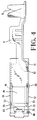
- Figs. 2 to 5 show an embodiment that is modified with respect to the locking lances 77, 79.
- the locking lances 77 and 79 are each formed in that a corresponding portion of the top part 51 and the bottom part 57, respectively, has been sheared through and pushed inwardly into the interor of the box portion 41.
- the locking stop 81 can be formed in the same manner.
- a further possibility consists in forming the locking projections by pushing the corresponding portion of the outer back-up spring inwardly in non-shearing manner, i.e. by forming a recess by inwardly directed pressure.
- the resiling effect desired for the locking projections 77 and 79 is rendered possible in this embodiment by the resilience of the part of the outer back-up spring surrounding the respective locking projection.
- the locking stop 81 is located opposite a transverse edge at the mating-side end of contact body 21, said transverse edge being constituted by the longitudinal end 23 on the mating side.
- the free ends of the locking lances 77 and 79 are each located opposite a transverse edge 82 on the wire terminating side, with the latter edge being formed by a cutout in the wire-terminating-side end of the top part 37 and the bottom part 83 of the contact body 21, respectively.
- the wire-terminating-side transverse edges 82 cooperating with the free ends of the locking lances 77 and 79 may also be constituted by the wire-terminating-side ends of the top part 37 and the bottom part 83 of the contact body 21, respectively.
- the angle between the locking lances 77, 79 and the top part 51, respectively the bottom part 57, of the outer back-up spring body 39 is selected such that the free ends of the locking lances 77, 79, in the unstressed condition, are located at the level of the transverse edges 82 on the wire terminating side.
- the outer back-up spring is slid onto the contact 11 from the mating-side free ends of the contact spring arms 25.
- the locking lances 77 hit the mating-side longitudinal ends 23 of contact body 21, these lances evade in resilient manner and slide across top part 37 and bottom part 83 of contact body 21, until the free ends thereof have passed across the transverse edges 82 on the wire terminating side and the locking lances 77 and 79 are allowed to return into their unstressed position.
- locking stop 81 cooperaates with the mating-side longitudinal end 23 of the top part 37 of the contact body 21 in such a manner that a further sliding motion of the outer back-up spring 13 in the direction towards wire terminating portion 15 is prevented.
- a backward sliding motion of the outer back-up spring 13 in the direction towards the mating-side end of the contact 11 is prevented by the cooperation between the locking lances 77, 79 and the transverse edges 82.
- the outer back-up spring 13 is in this position snapped onto contact body 21 and is locked there.
- An operation such as moving locking lances disposed on the outer back-up spring into associated locking recesses on the contact, or bending of locking lances of the outer back-up spring about web portions of the contact is not necessary any more with the design of contact and outer back-up spring according to the invention. All operations on contact 11 and outer back-up spring 13, which serve for the locking process, can thus be carried out while contact 11 and outer back-up spring 13 are still separated from each other, preferably even on the flat stamped blanks before these are bent into the shape of contact 11 and outer back-up spring 13, respectively.
- the outer back-up spring 13 has been created by bending a stamped sheet metal part in the form of a box. An abutment joint 87 formed during such bending is closed by welding. Preferably, a laser spot welding process is used therefor. Two welding spots 89 are shown in Figs. 2 and 4.
- the outer back-up spring body 39 By the configuration of the outer back-up spring body 39 according to the invention such that it encloses the contact spring arms 25 across the entire length thereof, good protection of the contact spring arms 25 against damage thereof is provided at the same time.
- rounded corners and edges render possible easy insertion of the contact 11 provided with outer back-up spring 13 into a contact receiving chamber 69 of connector housing 71.
- the inner contact spring part 21 has upper and lower tab portions 181, 182, respectively, each of which project in the same direction as corresponding locking lances 77,79.
- the tabs 181, 182 form stop edges 183, 184 for engagement against the free end of the tabs 77, 79.
- the tabs 181, 182 are formed such that they are adjacent to the inner surface 185, 186.
- the outer back-up spring 18 is snapped over the inner contact spring, the locking lances 77, 79 are snapped into place within the opening formed by the tabs 181, 182, and engage edges 183, 184 as shown best in Figure 5.
- the tabs 181, 182 prevent the tabs 77, 79 from slipping into the interior of the inner contact body, thereby allowing longitudinal movement of the back-up spring relative to the inner contact part.
Landscapes
- Connector Housings Or Holding Contact Members (AREA)
- Coupling Device And Connection With Printed Circuit (AREA)
Priority Applications (2)
| Application Number | Priority Date | Filing Date | Title |
|---|---|---|---|
| EP95101079A EP0650224B1 (de) | 1991-06-03 | 1992-05-26 | Elektrischer Kontakt |
| DE9218732U DE9218732U1 (de) | 1991-06-03 | 1992-05-26 | Elektrischer Kontakt |
Applications Claiming Priority (4)
| Application Number | Priority Date | Filing Date | Title |
|---|---|---|---|
| DE9106776U DE9106776U1 (de) | 1991-06-03 | 1991-06-03 | Elektrischer Steckkontakt |
| DE9106776U | 1991-06-03 | ||
| GB929206962A GB9206962D0 (en) | 1992-03-31 | 1992-03-31 | Electrical contact |
| GB9206962 | 1992-03-31 |
Related Child Applications (1)
| Application Number | Title | Priority Date | Filing Date |
|---|---|---|---|
| EP95101079.2 Division-Into | 1992-05-26 |
Publications (3)
| Publication Number | Publication Date |
|---|---|
| EP0517077A2 true EP0517077A2 (de) | 1992-12-09 |
| EP0517077A3 EP0517077A3 (en) | 1993-07-07 |
| EP0517077B1 EP0517077B1 (de) | 1997-07-23 |
Family
ID=25958249
Family Applications (2)
| Application Number | Title | Priority Date | Filing Date |
|---|---|---|---|
| EP92108885A Expired - Lifetime EP0517077B1 (de) | 1991-06-03 | 1992-05-26 | Elektrischer Kontakt |
| EP95101079A Expired - Lifetime EP0650224B1 (de) | 1991-06-03 | 1992-05-26 | Elektrischer Kontakt |
Family Applications After (1)
| Application Number | Title | Priority Date | Filing Date |
|---|---|---|---|
| EP95101079A Expired - Lifetime EP0650224B1 (de) | 1991-06-03 | 1992-05-26 | Elektrischer Kontakt |
Country Status (5)
| Country | Link |
|---|---|
| US (1) | US5338229A (de) |
| EP (2) | EP0517077B1 (de) |
| BR (1) | BR9202113A (de) |
| DE (2) | DE69228392T2 (de) |
| ES (1) | ES2129682T3 (de) |
Cited By (11)
| Publication number | Priority date | Publication date | Assignee | Title |
|---|---|---|---|---|
| US5468163A (en) * | 1993-07-22 | 1995-11-21 | The Whitaker Corporation | Electrical terminal for use with short circuit spring contacts |
| EP0656674A3 (de) * | 1993-12-03 | 1996-04-03 | Whitaker Corp | Elektrische Anschlussbuchse mit einer Überfeder. |
| US5653616A (en) * | 1994-06-13 | 1997-08-05 | The Whitaker Corporation | Electrical receptacle terminal |
| EP0711009A3 (de) * | 1994-11-02 | 1997-12-03 | Leopold Kostal GmbH & Co. KG | Elektrische Steckverbindung |
| US5921821A (en) * | 1996-08-08 | 1999-07-13 | Sumitomo Wiring Systems, Ltd. | Terminal fitting |
| EP0727842A3 (de) * | 1995-02-17 | 1999-07-21 | The Whitaker Corporation | Einstückige Ansschlussbüchse |
| US5951336A (en) * | 1996-07-25 | 1999-09-14 | Sumitomo Wiring Systems, Ltd. | Terminal fitting |
| US5975964A (en) * | 1996-07-25 | 1999-11-02 | Sumitomo Wiring Systems, Ltd. | Female terminal fitting |
| FR2794293A1 (fr) * | 1999-05-26 | 2000-12-01 | Cinch Connecteurs Sa | Organe femelle de contact electrique |
| EP0926767A3 (de) * | 1997-12-17 | 2001-05-02 | Mecanismos Auxiliares Industriales S.A. M.A.I.S.A. | Verbessertes weibliches Endstück |
| FR2891670A1 (fr) * | 2005-10-04 | 2007-04-06 | Bosch Gmbh Robert | Douille de contact equipee de lamelles d'ecartement en plus des lamelles de contact. |
Families Citing this family (42)
| Publication number | Priority date | Publication date | Assignee | Title |
|---|---|---|---|---|
| FR2713833B1 (fr) * | 1993-12-15 | 1996-02-09 | Cinch Connecteurs Sa | Organe femelle de contact électrique et élément de boîtier de connecteur électrique destiné à recevoir un tel organe. |
| FR2717624B1 (fr) * | 1994-03-21 | 1996-04-26 | Cinch Connecteurs Sa | Organe de contact électrique femelle. |
| DE19517353C1 (de) * | 1995-05-11 | 1996-04-04 | Siemens Ag | Kontaktfeder |
| DE19602822C2 (de) * | 1996-01-26 | 1998-02-19 | Siemens Ag | Kontaktfeder |
| FR2749442B1 (fr) * | 1996-06-03 | 1998-07-10 | Framatome Connectors Int | Borne de contact electrique femelle a structure reforcee |
| FR2749441B1 (fr) * | 1996-06-03 | 1998-07-10 | Framatome Connectors Int | Borne de contact electrique femelle a pression de contact controlee |
| FR2783638B1 (fr) * | 1998-09-22 | 2000-10-13 | Cinch Connecteurs Sa | Organe de contact electrique femelle |
| US6152787A (en) * | 1999-08-30 | 2000-11-28 | Delphi Technologies, Inc. | One piece terminal |
| EP1271702B2 (de) * | 2001-06-22 | 2010-06-02 | Delphi Technologies, Inc. | Elektrische Anschlussbuchse |
| FR2833767A1 (fr) * | 2001-12-13 | 2003-06-20 | Sylea | Organe de contact electrique |
| DE10224683A1 (de) * | 2002-06-04 | 2003-12-18 | Bosch Gmbh Robert | Geschweißter Meanderkontakt |
| DE10335196B3 (de) * | 2003-07-30 | 2005-04-07 | Yazaki Europe Ltd., Hemel Hempstead | Kontaktbuchse für einen Flachstecker |
| JP4514645B2 (ja) * | 2004-07-12 | 2010-07-28 | タイコエレクトロニクスジャパン合同会社 | 雌型端子 |
| US7976353B2 (en) * | 2006-09-29 | 2011-07-12 | Tyco Electronics Corporation | Two-piece electrical terminal |
| TWI319248B (en) | 2007-02-01 | 2010-01-01 | Ks Terminals Inc | Electrical socket connector and female ternimal therein |
| DE102007032992A1 (de) * | 2007-07-16 | 2009-01-29 | Dafra Kontakt Tehnologija D.O.O. | Federkontakt für eine elektrische Steckverbindung und Steckverbindung |
| DE102007044412A1 (de) * | 2007-09-18 | 2009-03-19 | Lear Corp., Southfield | Elektrische Verbinderbaugruppe |
| US8366497B2 (en) * | 2009-06-17 | 2013-02-05 | Lear Corporation | Power terminal |
| DE102012017949A1 (de) * | 2011-09-28 | 2013-03-28 | Sumitomo Wiring Systems, Ltd. | Anschlusspassstück |
| US8951051B2 (en) | 2011-10-10 | 2015-02-10 | Lear Corporation | Connector having optimized tip |
| US9308636B2 (en) | 2012-02-03 | 2016-04-12 | Milwaukee Electric Tool Corporation | Rotary hammer with vibration dampening |
| DE102014009208B4 (de) * | 2013-06-21 | 2018-08-09 | Lear Corporation | Elektrische anschlussanordnung |
| US9905953B1 (en) | 2016-09-30 | 2018-02-27 | Slobodan Pavlovic | High power spring-actuated electrical connector |
| DE102016125764A1 (de) * | 2016-12-28 | 2018-06-28 | Lear Corporation | Zweistückige elektrische clean-body-anschlussbuchse |
| DE112018000476B4 (de) | 2017-01-23 | 2023-06-15 | Molex, Llc | Elektrischer Anschlusskontakt und Verbinderanordnung damit |
| DE102018106646A1 (de) * | 2017-03-22 | 2018-09-27 | Hirschmann Automotive Gmbh | Kontaktelement für einen Steckverbinder |
| US10283889B2 (en) | 2017-09-14 | 2019-05-07 | Lear Corporation | Electrical terminal with balanced front end protection |
| US10283895B1 (en) | 2017-12-20 | 2019-05-07 | Lear Corporation | Electrical terminal assembly with split shroud |
| US10396482B2 (en) | 2017-12-20 | 2019-08-27 | Lear Corporation | Electrical terminal assembly with locked spring member |
| USD882525S1 (en) * | 2018-01-30 | 2020-04-28 | Molex, Llc | Connector terminal |
| USD855574S1 (en) * | 2018-01-30 | 2019-08-06 | Molex, Llc | Connector terminal |
| CN111937250B (zh) | 2018-02-26 | 2022-09-30 | 皇家精密制品有限责任公司 | 用于高功率应用的弹簧致动式电连接器 |
| CN108616017B (zh) * | 2018-03-26 | 2020-07-24 | 番禺得意精密电子工业有限公司 | 转接连接器 |
| WO2019237009A1 (en) | 2018-06-07 | 2019-12-12 | Royal Precision Products, Llc | Electrical connector system with internal spring component |
| WO2020150399A1 (en) | 2019-01-15 | 2020-07-23 | Royal Precision Products, Llc | Shielded electrical connector system with internal spring component |
| DE112020000459T5 (de) | 2019-01-21 | 2021-11-25 | Royal Precision Products, Llc | Stromverteilungsanordnung mit schraubenlosem sammelschienensystem |
| US11721942B2 (en) | 2019-09-09 | 2023-08-08 | Eaton Intelligent Power Limited | Connector system for a component in a power management system in a motor vehicle |
| CN114787815A (zh) | 2019-09-09 | 2022-07-22 | 伊顿智能动力有限公司 | 具有可读和可记录标记的连接器记录系统 |
| TWI734244B (zh) * | 2019-11-04 | 2021-07-21 | 大陸商東莞訊滔電子有限公司 | 電性端子以及電連接器 |
| JP7073429B2 (ja) * | 2020-03-18 | 2022-05-23 | 矢崎総業株式会社 | 端子付き電線の製造方法、及び、端子付き電線 |
| DE112021003695T5 (de) | 2020-07-29 | 2023-06-29 | Eaton Intelligent Power Limited | Verbindersystem einschliesslich eines verriegelungssystems |
| CN112838436B (zh) * | 2021-01-07 | 2022-05-31 | 苏州浪潮智能科技有限公司 | 一种风扇连接器免工具安装结构 |
Family Cites Families (9)
| Publication number | Priority date | Publication date | Assignee | Title |
|---|---|---|---|---|
| DE3241485A1 (de) * | 1982-11-10 | 1984-05-10 | Grote & Hartmann Gmbh & Co Kg, 5600 Wuppertal | Rundsteckhuelse mit ueberfeder |
| DE8236405U1 (de) * | 1982-12-24 | 1984-10-04 | Grote & Hartmann Gmbh & Co Kg, 5600 Wuppertal | Doppelflachfederkontakt mit Überfeder |
| JPS59138185U (ja) * | 1983-03-04 | 1984-09-14 | ホシデン株式会社 | ジヤツク |
| DE3502633C1 (de) * | 1985-01-26 | 1986-04-30 | Kabelwerke Reinshagen Gmbh, 5600 Wuppertal | Elektrischer Doppelflachfederkontakt |
| DE8508964U1 (de) * | 1985-03-26 | 1986-12-18 | Grote & Hartmann Gmbh & Co Kg, 5600 Wuppertal | Kastenfeder |
| JPS61237375A (ja) * | 1985-04-11 | 1986-10-22 | アンプ インコ−ポレ−テツド | レセプタクル端子 |
| FR2621180B1 (fr) * | 1987-09-28 | 1990-01-12 | Francelco Sa | Borne de contact electrique de type cage |
| GB8812881D0 (en) * | 1988-05-31 | 1988-07-06 | Amp Gmbh | Electrical connector |
| DE8810033U1 (de) * | 1988-08-05 | 1989-11-30 | TRW Daut + Rietz GmbH & Co KG, 8500 Nürnberg | Flachkontaktsteckhülse |
-
1992
- 1992-05-26 EP EP92108885A patent/EP0517077B1/de not_active Expired - Lifetime
- 1992-05-26 DE DE69228392T patent/DE69228392T2/de not_active Expired - Lifetime
- 1992-05-26 EP EP95101079A patent/EP0650224B1/de not_active Expired - Lifetime
- 1992-05-26 DE DE69221035T patent/DE69221035T2/de not_active Expired - Lifetime
- 1992-05-26 ES ES95101079T patent/ES2129682T3/es not_active Expired - Lifetime
- 1992-06-02 BR BR929202113A patent/BR9202113A/pt not_active IP Right Cessation
-
1993
- 1993-10-26 US US08/145,042 patent/US5338229A/en not_active Expired - Fee Related
Cited By (13)
| Publication number | Priority date | Publication date | Assignee | Title |
|---|---|---|---|---|
| EP0635904A3 (de) * | 1993-07-22 | 1996-04-03 | Whitaker Corp | Elektrische Anschlussbuchse zur Verwendung mit Kurzschlussfederkontakten. |
| US5468163A (en) * | 1993-07-22 | 1995-11-21 | The Whitaker Corporation | Electrical terminal for use with short circuit spring contacts |
| EP0656674A3 (de) * | 1993-12-03 | 1996-04-03 | Whitaker Corp | Elektrische Anschlussbuchse mit einer Überfeder. |
| US5653616A (en) * | 1994-06-13 | 1997-08-05 | The Whitaker Corporation | Electrical receptacle terminal |
| EP0688065A3 (de) * | 1994-06-13 | 1998-10-21 | The Whitaker Corporation | Elektrische Buchse |
| EP0711009A3 (de) * | 1994-11-02 | 1997-12-03 | Leopold Kostal GmbH & Co. KG | Elektrische Steckverbindung |
| EP0727842A3 (de) * | 1995-02-17 | 1999-07-21 | The Whitaker Corporation | Einstückige Ansschlussbüchse |
| US5975964A (en) * | 1996-07-25 | 1999-11-02 | Sumitomo Wiring Systems, Ltd. | Female terminal fitting |
| US5951336A (en) * | 1996-07-25 | 1999-09-14 | Sumitomo Wiring Systems, Ltd. | Terminal fitting |
| US5921821A (en) * | 1996-08-08 | 1999-07-13 | Sumitomo Wiring Systems, Ltd. | Terminal fitting |
| EP0926767A3 (de) * | 1997-12-17 | 2001-05-02 | Mecanismos Auxiliares Industriales S.A. M.A.I.S.A. | Verbessertes weibliches Endstück |
| FR2794293A1 (fr) * | 1999-05-26 | 2000-12-01 | Cinch Connecteurs Sa | Organe femelle de contact electrique |
| FR2891670A1 (fr) * | 2005-10-04 | 2007-04-06 | Bosch Gmbh Robert | Douille de contact equipee de lamelles d'ecartement en plus des lamelles de contact. |
Also Published As
| Publication number | Publication date |
|---|---|
| EP0517077B1 (de) | 1997-07-23 |
| EP0517077A3 (en) | 1993-07-07 |
| EP0650224A2 (de) | 1995-04-26 |
| BR9202113A (pt) | 1993-02-02 |
| ES2129682T3 (es) | 1999-06-16 |
| DE69228392D1 (de) | 1999-03-18 |
| EP0650224B1 (de) | 1999-02-03 |
| DE69221035D1 (de) | 1997-09-04 |
| EP0650224A3 (de) | 1996-10-02 |
| DE69228392T2 (de) | 1999-08-26 |
| DE69221035T2 (de) | 1998-06-10 |
| US5338229A (en) | 1994-08-16 |
Similar Documents
| Publication | Publication Date | Title |
|---|---|---|
| EP0517077B1 (de) | Elektrischer Kontakt | |
| EP0517076B1 (de) | Elektrischer Kontakt | |
| US5246390A (en) | Electrical contact | |
| EP0678936B1 (de) | Reibkorrosionsfreie Miniatur-Steckbuchse | |
| EP0727842B1 (de) | Einstückige Ansschlussbüchse | |
| KR100503824B1 (ko) | 원피스콘택스프링 | |
| EP0600419B1 (de) | Elektrische Anschlussbuchse | |
| EP0932917B1 (de) | Elektrischer verbinder mit einem gehäuse und einem elektrischen kontaktelement | |
| JP2644548B2 (ja) | 電気コネクタ | |
| EP0795930B1 (de) | Elektrische Aufnahmebuchse für Stift mit hoher Kontaktkraft | |
| US4298242A (en) | Electrical socket contact | |
| EP0687033A2 (de) | Buchsenklemme für Hochstrom | |
| US5611716A (en) | Electrical contact having improved secondary locking surfaces | |
| JPH06260221A (ja) | 電気端子組立体及びそれを用いる電気コネクタ | |
| JPH07272784A (ja) | リセプタクルコンタクト | |
| JP3273967B2 (ja) | リセプタクル型コンタクト | |
| US11381009B2 (en) | Contact and connector | |
| US6287157B1 (en) | Connector assembly | |
| JP2021068623A (ja) | 雌端子 | |
| JPH0613118A (ja) | リセプタクル型コンタクト | |
| JP2026026576A (ja) | シールド端子 | |
| JPH0515342U (ja) | 端子のこじり防止機構 | |
| JPH10241768A (ja) | 雌型電気端子 | |
| GB2306807A (en) | Socket contact for an electrical connector | |
| JP2002231360A (ja) | 雌型端子 |
Legal Events
| Date | Code | Title | Description |
|---|---|---|---|
| PUAI | Public reference made under article 153(3) epc to a published international application that has entered the european phase |
Free format text: ORIGINAL CODE: 0009012 |
|
| AK | Designated contracting states |
Kind code of ref document: A2 Designated state(s): DE ES FR GB IT NL PT |
|
| RAP1 | Party data changed (applicant data changed or rights of an application transferred) |
Owner name: THE WHITAKER CORPORATION |
|
| PUAL | Search report despatched |
Free format text: ORIGINAL CODE: 0009013 |
|
| AK | Designated contracting states |
Kind code of ref document: A3 Designated state(s): DE ES FR GB IT NL PT |
|
| 17P | Request for examination filed |
Effective date: 19940104 |
|
| 17Q | First examination report despatched |
Effective date: 19950126 |
|
| GRAG | Despatch of communication of intention to grant |
Free format text: ORIGINAL CODE: EPIDOS AGRA |
|
| GRAH | Despatch of communication of intention to grant a patent |
Free format text: ORIGINAL CODE: EPIDOS IGRA |
|
| GRAH | Despatch of communication of intention to grant a patent |
Free format text: ORIGINAL CODE: EPIDOS IGRA |
|
| GRAA | (expected) grant |
Free format text: ORIGINAL CODE: 0009210 |
|
| AK | Designated contracting states |
Kind code of ref document: B1 Designated state(s): DE ES FR GB IT NL PT |
|
| DX | Miscellaneous (deleted) | ||
| PG25 | Lapsed in a contracting state [announced via postgrant information from national office to epo] |
Ref country code: IT Free format text: LAPSE BECAUSE OF FAILURE TO SUBMIT A TRANSLATION OF THE DESCRIPTION OR TO PAY THE FEE WITHIN THE PRE;WARNING: LAPSES OF ITALIAN PATENTS WITH EFFECTIVE DATE BEFORE 2007 MAY HAVE OCCURRED AT ANY TIME BEFORE 2007. THE CORRECT EFFECTIVE DATE MAY BE DIFFERENT FROM THE ONE RECORDED.SCRIBED TIME-LIMIT Effective date: 19970723 Ref country code: NL Free format text: LAPSE BECAUSE OF FAILURE TO SUBMIT A TRANSLATION OF THE DESCRIPTION OR TO PAY THE FEE WITHIN THE PRESCRIBED TIME-LIMIT Effective date: 19970723 Ref country code: ES Free format text: THE PATENT HAS BEEN ANNULLED BY A DECISION OF A NATIONAL AUTHORITY Effective date: 19970723 |
|
| ET | Fr: translation filed | ||
| REF | Corresponds to: |
Ref document number: 69221035 Country of ref document: DE Date of ref document: 19970904 |
|
| PG25 | Lapsed in a contracting state [announced via postgrant information from national office to epo] |
Ref country code: PT Effective date: 19971028 |
|
| NLV1 | Nl: lapsed or annulled due to failure to fulfill the requirements of art. 29p and 29m of the patents act | ||
| PG25 | Lapsed in a contracting state [announced via postgrant information from national office to epo] |
Ref country code: GB Free format text: LAPSE BECAUSE OF NON-PAYMENT OF DUE FEES Effective date: 19980526 |
|
| PLBE | No opposition filed within time limit |
Free format text: ORIGINAL CODE: 0009261 |
|
| STAA | Information on the status of an ep patent application or granted ep patent |
Free format text: STATUS: NO OPPOSITION FILED WITHIN TIME LIMIT |
|
| 26N | No opposition filed | ||
| GBPC | Gb: european patent ceased through non-payment of renewal fee |
Effective date: 19980526 |
|
| REG | Reference to a national code |
Ref country code: FR Ref legal event code: ST Effective date: 20100129 |
|
| PG25 | Lapsed in a contracting state [announced via postgrant information from national office to epo] |
Ref country code: FR Free format text: LAPSE BECAUSE OF NON-PAYMENT OF DUE FEES Effective date: 20090602 |
|
| PGFP | Annual fee paid to national office [announced via postgrant information from national office to epo] |
Ref country code: FR Payment date: 20080519 Year of fee payment: 17 |
|
| PGFP | Annual fee paid to national office [announced via postgrant information from national office to epo] |
Ref country code: DE Payment date: 20110527 Year of fee payment: 20 |
|
| REG | Reference to a national code |
Ref country code: DE Ref legal event code: R071 Ref document number: 69221035 Country of ref document: DE |
|
| REG | Reference to a national code |
Ref country code: DE Ref legal event code: R071 Ref document number: 69221035 Country of ref document: DE |
|
| PG25 | Lapsed in a contracting state [announced via postgrant information from national office to epo] |
Ref country code: DE Free format text: LAPSE BECAUSE OF EXPIRATION OF PROTECTION Effective date: 20120530 |