EP0517295B1 - Commutateur à moyenne tension à trois positions isolé dans de l'hexafluorure de soufre - Google Patents
Commutateur à moyenne tension à trois positions isolé dans de l'hexafluorure de soufre Download PDFInfo
- Publication number
- EP0517295B1 EP0517295B1 EP92201448A EP92201448A EP0517295B1 EP 0517295 B1 EP0517295 B1 EP 0517295B1 EP 92201448 A EP92201448 A EP 92201448A EP 92201448 A EP92201448 A EP 92201448A EP 0517295 B1 EP0517295 B1 EP 0517295B1
- Authority
- EP
- European Patent Office
- Prior art keywords
- switch
- contact
- arms
- fixed
- contacts
- Prior art date
- Legal status (The legal status is an assumption and is not a legal conclusion. Google has not performed a legal analysis and makes no representation as to the accuracy of the status listed.)
- Expired - Lifetime
Links
- SFZCNBIFKDRMGX-UHFFFAOYSA-N sulfur hexafluoride Chemical compound FS(F)(F)(F)(F)F SFZCNBIFKDRMGX-UHFFFAOYSA-N 0.000 title claims abstract description 18
- 229960000909 sulfur hexafluoride Drugs 0.000 title claims abstract description 16
- 238000005086 pumping Methods 0.000 claims abstract description 12
- 239000011810 insulating material Substances 0.000 claims description 7
- 241000722921 Tulipa gesneriana Species 0.000 claims description 6
- 239000012530 fluid Substances 0.000 claims description 6
- 230000000295 complement effect Effects 0.000 claims description 5
- 239000000470 constituent Substances 0.000 claims description 5
- 239000002184 metal Substances 0.000 abstract description 6
- 239000012212 insulator Substances 0.000 description 17
- 238000011144 upstream manufacturing Methods 0.000 description 11
- 238000002955 isolation Methods 0.000 description 4
- OKTJSMMVPCPJKN-UHFFFAOYSA-N Carbon Chemical compound [C] OKTJSMMVPCPJKN-UHFFFAOYSA-N 0.000 description 3
- 229910052799 carbon Inorganic materials 0.000 description 3
- 238000007689 inspection Methods 0.000 description 3
- 239000004020 conductor Substances 0.000 description 2
- 230000037431 insertion Effects 0.000 description 2
- 238000003780 insertion Methods 0.000 description 2
- 230000015572 biosynthetic process Effects 0.000 description 1
- 238000010276 construction Methods 0.000 description 1
- 230000007547 defect Effects 0.000 description 1
- 230000008021 deposition Effects 0.000 description 1
Images


Classifications
-
- H—ELECTRICITY
- H01—ELECTRIC ELEMENTS
- H01H—ELECTRIC SWITCHES; RELAYS; SELECTORS; EMERGENCY PROTECTIVE DEVICES
- H01H33/00—High-tension or heavy-current switches with arc-extinguishing or arc-preventing means
- H01H33/02—Details
- H01H33/022—Details particular to three-phase circuit breakers
-
- H—ELECTRICITY
- H01—ELECTRIC ELEMENTS
- H01H—ELECTRIC SWITCHES; RELAYS; SELECTORS; EMERGENCY PROTECTIVE DEVICES
- H01H33/00—High-tension or heavy-current switches with arc-extinguishing or arc-preventing means
- H01H33/70—Switches with separate means for directing, obtaining, or increasing flow of arc-extinguishing fluid
- H01H33/88—Switches with separate means for directing, obtaining, or increasing flow of arc-extinguishing fluid the flow of arc-extinguishing fluid being produced or increased by movement of pistons or other pressure-producing parts
- H01H33/90—Switches with separate means for directing, obtaining, or increasing flow of arc-extinguishing fluid the flow of arc-extinguishing fluid being produced or increased by movement of pistons or other pressure-producing parts this movement being effected by or in conjunction with the contact-operating mechanism
- H01H33/91—Switches with separate means for directing, obtaining, or increasing flow of arc-extinguishing fluid the flow of arc-extinguishing fluid being produced or increased by movement of pistons or other pressure-producing parts this movement being effected by or in conjunction with the contact-operating mechanism the arc-extinguishing fluid being air or gas
-
- H—ELECTRICITY
- H01—ELECTRIC ELEMENTS
- H01H—ELECTRIC SWITCHES; RELAYS; SELECTORS; EMERGENCY PROTECTIVE DEVICES
- H01H31/00—Air-break switches for high tension without arc-extinguishing or arc-preventing means
- H01H31/003—Earthing switches
-
- H—ELECTRICITY
- H01—ELECTRIC ELEMENTS
- H01H—ELECTRIC SWITCHES; RELAYS; SELECTORS; EMERGENCY PROTECTIVE DEVICES
- H01H33/00—High-tension or heavy-current switches with arc-extinguishing or arc-preventing means
- H01H33/70—Switches with separate means for directing, obtaining, or increasing flow of arc-extinguishing fluid
- H01H33/88—Switches with separate means for directing, obtaining, or increasing flow of arc-extinguishing fluid the flow of arc-extinguishing fluid being produced or increased by movement of pistons or other pressure-producing parts
- H01H33/886—Switches with separate means for directing, obtaining, or increasing flow of arc-extinguishing fluid the flow of arc-extinguishing fluid being produced or increased by movement of pistons or other pressure-producing parts by movement of rotating pistons
-
- H—ELECTRICITY
- H01—ELECTRIC ELEMENTS
- H01H—ELECTRIC SWITCHES; RELAYS; SELECTORS; EMERGENCY PROTECTIVE DEVICES
- H01H9/00—Details of switching devices, not covered by groups H01H1/00 - H01H7/00
- H01H9/10—Adaptation for built-in fuses
- H01H9/102—Fuses mounted on or constituting the movable contact parts of the switch
Definitions
- This invention relates to a medium voltage operating-isolating switch with three positions insulated in sulphur hexafluoride according to the preamble of claim 1 as well as to a compact fluid-insulated three position medium voltage operating-isolating switch according to the preamble of claim 13 (see for example FR-A-1367 073).
- Switches of current construction and use do not offer this possibility, for example in switches of rotary contact type it is possible to earth the user but without the simultaneous possibility, when in the isolated position, of drainage between the part under tension and the user, so that a stray current can accidentally discharge onto this latter.
- a fuse is present this cannot be earthed simultaneously upstream and downstream.
- a further separate parallel device must be provided for earthing that region upstream or downstream of the fuse which is not earthed.
- EP 0 201 695 is known a three-pole operating-isolating switch, insulated in SF 6 , with three operating positions, namely closed, isolated and earthed positions, in which a separated control system is provided for earthing the switch.
- This line contact switch has a non-visible electric contact for earthing, since this electric contact is sloped with respect a vertical axis of the switch.
- a visible isolator with a three-position rotary blade contact is combined with the operating switch, and both have to be operated both for putting the switch on-load and for earthing the user.
- a further separate device is in fact provided for earthing upstream and downstream of the fuse.
- line contact switches Although other line contact switches have a visible isolator for earthing, they have to comprise a second device which is also visible and comprises a second inspection door. If a fuse is present, this second device is doubled for earthing upstream and downstream of the fuse.
- CH 341 209 describes a high voltage electro-pneumatic operating-isolating switch of the type straight-movement, in which two electric contacts determine two separate different operating positions, namely closed and isolated positions.
- a spurt of compressed air is directed onto the contacts and into the so-called tulip element by a pumping device (in particular, by an axial bellows) in order to prevent eddy currents and voltaic arcs.
- cylinder-piston pumping devices are associated with the moving contacts arranged on a relative arm by means of hinged levers, to feed fluid onto the cooperating contacts or into the insulating nozzle containing the so-called tulip element.
- the contacts and pumping device are arranged one after the other but at a certain distance apart, because of which during its operation the pumping element can be soiled with carbon-containing residues and consequently discharge to earth, in addition to having the drawbacks of the previously described switches.
- An object of the present invention is to provide a medium voltage operating-isolating switch with three positions insulated in sulphur hexafluoride which solves the aforesaid problems in terms of positioning, single operation and constructional simplicity of the pole switch with or without a fuse.
- a further object is to provide a switch with maximum possible visibility of isolation or effective earthing.
- a further but not final object is to provide a switch the component parts of which do not require special positioning within the containing frame, but instead can be directly mounted away from it before insertion.
- a further object is to provide a switch in which there is a reduced possibility of the formation of carbon-containing residues, with the danger of possible discharges to earth.
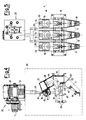
- a medium voltage operating-isolating switch with three positions insulated in sulphur hexafluoride comprises essentially a set of three insulating base support elements or insulators 11 for a set of three poles mounted on a support beam 12.
- An upper fixed contact 14 with an associated tulip element 16 comprising a male arcing contact 17 and contained in an insulating nozzle 15 are fixed respectively onto each support element 11, which extends upperly into a pumping cylinder 13.
- the fixed contact 14 is connected in known manner to a respective bus bar 18.
- the support element 11 also carries a lower contact 19 connected to an earthing plate 21 via a through insulator 20.
- a third intermediate contact 22 is fixed to the support element 11 and is secured to a U-piece 23, in holes 24 of which there is pivoted a T-shaped arm 25 in the form of two spaced-apart facing plates, carrying at its free end a pair of arcing contacts 26.
- cup springs 45 Electrical contact between the U-piece 23 and the arm 25 is ensured by cup springs 45.
- This assembly forms a moving contact which is connected via a through insulator 43 to a current inlet or outlet.
- the pivoting is provided by a shaft 27 of insulating material which passes through each of the three poles, is supported on the support elements 11, and supports the cup springs 45 in addition to the U-pieces 23 and the arm 25.
- the arm 25 is also connected to and its position controlled by a second insulating shaft 28, which also passes through all three arms of the moving contacts to act as a pivot.
- the arm 25 is rotated by two insulating rods 29 which emerge from a sealed metal container 30 containing sulphur hexafluoride and from metal seal bellows 31, and are controlled by a quick snap-engagement mechanism for the three positions, which is indicated overall by 32 and can be operated from the outside of the front of the switch by a rod, not shown.
- This device converts rotation into a linear movement determining the three operating positions, namely closed, isolated and earthed.
- two insulating levers 33 are provided, each having a pair of through holes 34 and 35 through which the shafts 27 and 28 are inserted.
- the levers 33 are angular and at their free end they are connected by a pin 36 to a pair of second levers 37 which move a piston 38 connected to them by a further pin 39.
- a metal draining blade 44 of equivalent shape has to be arranged between the support element 11 and the cylinder 13 to prevent any current circulation and passage between the isolated parts.
- Such a structure provides a simple operating-isolating switch without fuses.
- a bar 41 joining three contacts 42 on the support elements is mounted in a suitable seat 40 in the lower part of the support element 11 at a sufficient distance from the lower contact 19 to ensure the necessary isolation required by the regulations for the relative class, and is earthed as in the case of the beam 12.
- the lower contact 19 is completely isolated by eliminating the through insulator 20 and the through insulator 43 and connecting the two contacts 22 and 19 together downstream and upstream of a fuse 46.
- the fuse outlet is again connected to a through insulator entirely similar to 43.
- each T-shaped arm 25 has to carry a single contact 47 for engagement with said contacts 42.
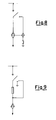
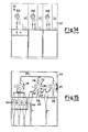
- Both the switch provided with only the fixed contacts 19 and moving contacts 26 and the switch provided with said contacts and with further fixed contacts 42 and moving contacts 47 are diagrammatically represented in the schematics of Figures 8 and 9 in the isolated position. These schematics again show that earthing can be achieved by a single arm carrying the moving contact, and that if a fuse is present earthing can be achieved both upstream and downstream of the fuse, again by a single arm carrying moving contacts.
- the switch is provided with fuses ( Figure 3), according to a preferred embodiment of the present invention the fuses 46 are positioned horizontally in an extractable drawer 50 aligned below the insulators coaxial with the three constituent poles of the switch. This positioning of the fuses allows them to be easily extracted and replaced frontally.
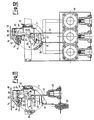
- Figures 4 and 6 show how the switch of the present invention can be comfortably assembled in all its essential parts on a rear beam 12 in the workshop.
- the beam has merely to be fixed to the interior of the panel structure and the relative conductors connected. This thus eliminates the need for arranging the contacts or special connectors for the insulated support elements in predetermined positions within the panel.
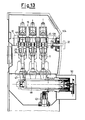
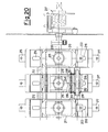
- Figures 10-13 show a further medium voltage operating-isolating switch with three positions insulated in sulphur hexafluoride according to an other preferred embodiment of the present invention in which the set of three insulating base support elements 11 is arranged transversely to the panel.
- equal reference numerals indicate equal elements.
- the fixed contact 14 is connected in known manner to a respective bus bar, not shown, and the through insulator 20 to an earthing plate, not shown.
- the pivoting is achieved by a shaft 27 of insulating material which is inserted through each of the three poles and is supported by the U-pieces 23 and the support elements 11.
- the arms 25 of the three poles are fixed by pins to the shaft 27, coaxial to which there are also the springs 45.
- the arms 25 are rotated by a flanged extension 128 thereto, which is connected to a complementary flange 124 also extending into a shaft portion emerging from a sealed metal container, not shown, containing the sulphur hexafluoride.
- a quick snap-action mechanism indicated overall by 32, for engaging the three positions.
- the upper front part of the panel comprises inspection doors 48 and seats 49 for the insertion of the operating lever (not shown) to be associated with each quick snap-action mechanism 32 to switch between the three positions of the moving contacts 26 and optionally 47 of the switch.
- the switch is provided with fuses ( Figures 12 and 13), according to a preferred embodiment of the present invention the fuses 46 are positioned horizontally in an extractable drawer 50 aligned below the insulators and the three constituent poles of the switch. This positioning of the fuses also allows them to be easily extracted and replaced frontally.
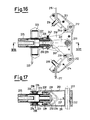
- a further compact three-position medium voltage operating-isolating switch insulated with fluid such as sulphur hexafluoride comprises essentially a set of three insulating base support elements or insulators 210, 211 of T-shape with curved arms and a widened base, mounted on two rear support ties 212, for example for the set of three poles.
- Each support element is of specular box type and consists of two mutually complementary parts 210 and 211 connected together by connection means which in the illustrated example consist of holes 213 and relative projecting pins 214 on one and the other of the parts 210, 211.
- This connection also fixes an upper fixed contact 215 with an associated male arcing contact 216, and a lower contact 217 with an associated male arcing contact 218.
- the fixed contact 215 is connected in known manner to a respective bus bar 219, whereas the lower contact 217 is connected via a through insulator 220 to an earthing plate 221.
- the support element 210, 211 When formed, the support element 210, 211 also carries in a hollow part of its widened base a third intermediate contact 222 which is fixed to the support element 210, 211 by a U-piece 223 closed lowerly and provided with pin extensions 224 on which there is pivoted a hollow cylindrical support 225 of insulating material for a telescopic arm connected to the intermediate contact 222.
- the pin extensions 224 lie within the cylinder 225 and are maintained rigid with a first fixed expandable outer cylindrical portion 227 of said telescopic arm. Electrical contact is ensured by cup springs 235 provided within recesses 236 formed in the pin extensions 224 and interacting between the support element 210, 211 and said recesses 236.
- a second cylindrical portion 228 is slidingly guided within said fixed portion 227 and carries at its free end, rigidly joined to its interior, a tulip contact element 229 acting as a female arcing contact. The outer part of this free end of the second portion 228 is supported within an annular support element 230 which is pivoted at 226 within a first end of two half-arms 231 of insulating material.
- the other end of the two half-arms 231 is provided with a through hole 232 and is pivoted to the support element 210, 211 in further holes by a central shaft 233, which is also the operating shaft.
- a quick snap-action mechanism 237 is connected to the shaft 233 in a lateral position on one side.
- the annular support element 230 comprises a front hole 234 constituting the emission portion for the fluid, such as sulphur hexafluoride, which quenches the arc and is contained in the expandable chamber defined by the two portions 227, 228 of the telescopic arm.
- the fluid such as sulphur hexafluoride
- This described telescopic arm assembly forms a moving contact which is connected via a through insulator 243 to a current inlet or outlet.
- through holes which are cut and open towards the outside to separate portions of the support elements, are provided to receive metal draining bars 244 of equivalent shape to the holes for preventing any current circulation and passage between the parts when isolated.
- Such a structure forms a simple compact fuse-less operating-isolating switch of fluid type which by making the cylinder pumping element for the fluid, such as sulphur hexafluoride, rigid with and incorporated in the moving arm prevents deposition of any carbon-containing residues and hence avoids operational defects and discharges to earth.
- fluid such as sulphur hexafluoride
- U-shaped contact elements 239 of bar form are mounted on the lower part of the support element 210, 211 in correspondence with holes 238.
- the sides of the contact elements 239 are elastically yieldable and are mounted on the lower support tie 212, with their free ends facing a slot 240 formed centrally in two halves between the two support elements 210, 211.
- Into this slot 240 there is inserted a free end of an open L-shaped contact element 241 which is fixed in proximity to its other end to the body of the half-arms 231.
- the other end of the contact element 241 abuts against a contact extension 242 which is inserted radially into the top of the annular support element 230 so that it makes contact with the free end of the second portion 228 of the telescopic arm.
- each telescopic arm 227, 228 must comprise a contact extension 242 and a contact element 241 rigid with the half-arms 231 for engagement with said bar contact elements 239.
- Both the switch provided with only the fixed and moving contacts and the switch provided with said contacts and with further fixed and moving contacts are diagrammatically represented in the schematics of Figure 14 on the front of an electrical panel 250 in the isolated position. These schematics again show that earthing can be achieved by a single arm carrying the moving contact, and that if a fuse is present earthing can be achieved both upstream and downstream of the fuse again by a single arm carrying moving contacts.
- the switch is provided with fuses ( Figure 16), according to a preferred embodiment of the present invention the fuses 246 are positioned horizontally in an extractable drawer 250 aligned below the insulators coaxially with the three constituent poles of the switch. This positioning of the fuses also allows them to be easily extracted and replaced frontally.
- the switch of the present invention can be assembled in all its essential parts on the two rear ties 212 in the workshop. In this respect, when the switch has been assembled and completed on said ties, it has merely fixed on to be the interior of the panel structure and the relative conductors connected. This thus eliminates the need for arranging the contacts or special connectors for the insulated support elements in predetermined positions within the panel.
- each insulated support element and each rotary arm is suitable for use in a switch without or with fuses, so that the additional moving and fixed contacts can then be quickly fitted to them.
Landscapes
- Driving Mechanisms And Operating Circuits Of Arc-Extinguishing High-Tension Switches (AREA)
- Measuring Instrument Details And Bridges, And Automatic Balancing Devices (AREA)
- Suspension Of Electric Lines Or Cables (AREA)
- Switch Cases, Indication, And Locking (AREA)
- Fuses (AREA)
- Transformers For Measuring Instruments (AREA)
- Circuit Breakers (AREA)
- Pinball Game Machines (AREA)
Claims (19)
- Commutateur isolant fonctionnant à moyenne tension avec trois positions, comprenant un ensemble de trois pôles, chaque pôle comprenant un contact fixe (14) et un contact mobile (26), ledit contact fixe (14) portant, à l'intérieur d'un embout isolant (15), un élément associé en forme de tulipe (16), contenant un contact d'amorçage (17), et étant connecté à une barre de bus respective (18), ledit contact mobile (26) étant agencé sur un bras (25) pivotant entre une première position fermée, en engagement avec ledit contact fixe (14), une deuxième position isolée et une troisième position reliée à la terre, et un dispositif cylindre-piston (13, 38) associé par l'intermédiaire d'un levier isolé (33) à chacun desdits bras (25) portant lesdits contacts mobiles (26), pour pomper ledit hexafluorure de soufre dans ledit embout isolant (15), caractérisé en ce que le commutateur est isolé dans de l'hexafluorure de soufre, et le contact d'amorçage (17) est un contact mâle, en ce que lesdits contacts mobile (26) et fixe (14) de chaque pôle dudit ensemble de trois pôles sont agencés sur un élément parmi trois éléments supports de base isolants (11) fixés à une poutre unique formant support (12) et en ce qu'un élément d'écoulement métallique (44) est prévu entre chacun desdits éléments supports de base isolants (11) et desdits cylindres de pompage (13).
- Commutateur selon la revendication 1, caractérisé en ce que lesdits trois bras (25) portant lesdits contacts mobiles (26) comprennent deux trous traversants séparés (34, 35), à travers lesquels deux arbres (27, 28) en matériau isolant sont insérés, l'un (28) de ces derniers comportant, pivotant sur celui-ci, une tige isolante (29), sortant d'un conteneur isolé (30) contenant ledit hexafluorure de soufre, destiné à être connecté à un mécanisme à action à encliquetage rapide (32), pour s'engager dans lesdites trois positions, l'autre arbre (27) de ladite paire d'arbres portant un ensemble de trois leviers (37), pour actionner les pistons (38) desdits cylindres (13).
- Commutateur selon la revendication 1, caractérisé en ce que d'autres contacts (19, 42 ; 26, 47) peuvent être ajustés sur lesdits éléments supports de base isolants (11) et lesdits bras (25), pour mettre à la terre des fusibles (46) associés audit commutateur.
- Commutateur selon la revendication 1, caractérisé en ce que chacun desdits bras (25) est constitué d'une ou deux plaques pivotant sur un élément support relatif, par l'intermédiaire d'une pièce en U (23), faisant contact entre lesdites deux plaques desdits bras (25), et ladite pièce en U (23) étant réalisée par des ressorts (45) agencés de manière coaxiale sur ledit arbre pivotant (27).
- Tableau isolé comprenant au moins un commutateur selon l'une quelconque des revendications précédentes, caractérisé en ce qu'il comprend une porte frontale (48), destinée à observer les trois positions des éléments constitutifs des trois pôles.
- Tableau isolé selon la revendication 5, caractérisé en ce qu'il comprend un tiroir horizontal extractible vers l'avant (50), positionné au-dessous dudit commutateur, et contenant trois fusibles (46) axialement alignés avec lesdits trois pôles et situés au-dessous d'eux.
- Tableau isolé selon la revendication 5, caractérisé en ce qu'il comprend dans une position avant supérieure, un siège (49), destiné à insérer un levier d'actionnement pour ledit mécanisme à action à encliquetage rapide (32).
- Commutateur selon la revendication 1, caractérisé en ce que lesdits trois bras (25) portant lesdits contacts mobiles (26) sont de forme courbée, et sont fixes en étant séparés sur un arbre traversant (27) fait de matériau isolant, pivotant à l'intérieur de chacun desdits trois éléments supports (11), et faisant saillie d'un conteneur isolé contenant ledit hexafluorure de soufre, destiné à être connecté à un mécanisme à action à encliquetage rapide (32), pour s'engager dans lesdites trois positions, et agencé transversalement auxdits trois pôles, un ensemble de trois leviers (37) étant connecté audit arbre (27) pour actionner les pistons (38) desdits cylindres (13).
- Commutateur selon la revendication 1, caractérisé en ce que d'autres contacts (19, 42 ; 26, 27) peuvent être ajustés sur lesdits éléments supports isolants (11) et sur lesdits bras (25), pour mettre à la terre les fusibles associés audit commutateur.
- Commutateur selon la revendication 1, caractérisé en ce que chacun desdits bras est constitué de deux plaques fixées audit arbre, et pivotant par rapport à un élément support relatif par l'intermédiaire d'une pièce en U (23), faisant contact entre lesdites deux plaques desdits bras (25), et ladite pièce en U (23) étant réalisée par des ressorts (45) agencés de manière coaxiale sur ledit arbre pivotant.
- Tableau isolé comprenant au moins un commutateur selon l'une quelconque des revendications 8 à 10, caractérisé en ce qu'il comprend un tiroir horizontal extractible vers l'avant (50), positionné au-dessous dudit commutateur, et contenant un ensemble de trois fusibles (46) agencés parallèlement à l'axe desdits trois pôles.
- Tableau isolé selon la revendication 11, caractérisé en ce qu'il comprend dans une position avant supérieure, un siège (49), destiné à insérer un levier d'actionnement pour ledit mécanisme à action à encliquetage rapide (32).
- Commutateur compact, isolé par fluide, fonctionnant à moyenne tension, à trois positions, comprenant un ensemble de trois pôles, chaque pôle comprenant un contact fixe (215) et un contact mobile (229, 242), ledit contact fixe (215) portant un contact d'amorçage associé (216), et le contact mobile (229, 242) étant agencé sur un bras pivotant (227, 228), pouvant tourner entre une première position fermée en engagement avec ledit contact fixe (215), une deuxième position isolée et une troisième position reliée à la terre, et un dispositif de pompage à cylindre destiné à pomper le fluide sur ledit contact fixe (215), caractérisé en ce que ledit contact d'amorçage (216) est un contact mâle, en ce que lesdits contacts mobile et fixe de chaque pôle dudit ensemble de trois pôles sont agencés sur un élément parmi trois éléments supports de base isolants (210, 211) fixés à des liaisons formant supports (212), chacun desdits bras (227, 228) portant lesdits contacts mobiles (229, 242) étant de type télescopique, et comportant lesdits contacts mobiles (216), associés à celui-ci par l'intermédiaire d'un levier isolant (231), connecté à une tige d'actionnement, ledit dispositif à cylindre de pompage étant disposé à l'intérieur dudit bras rotatif (227, 228), et en ce qu'au moins un élément d'écoulement métallique (244) est prévu sur chacun desdits éléments supports isolants (210, 211), entre la partie portant ledit contact fixe (215) et la partie restante desdits éléments supports (210, 211).
- Commutateur selon la revendication 13, caractérisé en ce que lesdits éléments supports isolants sont du type en boite, sous la forme de deux parties complémentaires (210, 211), pouvant être fixées ensemble par des moyens de fixation mutuels (213, 214).
- Commutateur selon la revendication 13, caractérisé en ce que chacun desdits bras est constitué d'un support (225) pivotant par rapport à un élément support relatif (210, 211) au moyen d'une pièce en U (223), ledit support portant deux parties cylindriques pouvant mutuellement être dilatées (227, 228), l'une des deux au moins soutenant un élément de contact en tulipe (229), le contact entre ladite pièce en U (223) et lesdites parties cylindriques pouvant être dilatées (227, 228) étant réalisé par des ressorts (235) agencés de manière coaxiale par rapport à un pivot (224), par lequel ledit support (225) est pivoté par rapport à ladite pièce en U (223).
- Commutateur selon la revendication 15, caractérisé en ce qu'une extrémité libre dudit support pivotant (225) est soutenue dans un élément support annulaire (230) pivotant sur les extrémités de demi-bras (231) en matériau isolant qui peuvent être mis en rotation dans les trois positions par un arbre d'actionnement (233), fixé pour passer sur l'autre extrémité dudit demi-bras (231), et connecté à un mécanisme à action à encliquetage rapide (237).
- Commutateur selon la revendication 13, caractérisé en ce que d'autres contacts (217, 239 ; 229, 242) peuvent être ajustés sur lesdits éléments supports isolants (210, 211), et lesdits bras télescopiques (227, 228) dans des positions complémentaires pour mettre à la terre des fusibles (246) associés audit commutateur.
- Commutateur selon la revendication 17, caractérisé en ce que lesdits autres contacts pour mettre à la terre les fusibles (246) sont respectivement un élément de contact (241) soutenu sur des demi-bras (231) pivotant sur les éléments isolants desdits bras télescopiques (227, 228), une extension de contact (242), s'étendant depuis lesdits contacts mobiles, et des éléments de contact à barre (239), fixés auxdits éléments supports (210, 211), ledit élément de contact (241), ladite extension de contact (242) et lesdits éléments de contact à barre (239) étant connectés électriquement ensemble seulement lorsqu'ils sont dans la troisième position reliée à la terre.
- Tableau isolé comprenant au moins un commutateur selon l'une des revendications 13 à 18, caractérisé en ce qu'il comprend un tiroir horizontal extractible vers l'avant (250), positionné au-dessous dudit commutateur, et contenant un ensemble de trois fusibles (246) associés auxdits trois pôles.
Applications Claiming Priority (6)
| Application Number | Priority Date | Filing Date | Title |
|---|---|---|---|
| ITMI911435A IT1260588B (it) | 1991-05-24 | 1991-05-24 | Apparecchiatura di manovra-sezionatura a media tensione a tre posizioni isolate in esafluoruro di zolfo |
| ITMI911436A IT1252615B (it) | 1991-05-24 | 1991-05-24 | Apparecchiatura di manovra-sezionatura a media tensione a tre posizioni isolate in esafluoruro di zolfo. |
| ITMI911435 | 1991-05-24 | ||
| ITMI911436 | 1991-05-24 | ||
| ITMI911652A IT1248067B (it) | 1991-06-17 | 1991-06-17 | Apparecchiatura di manovra-sezionatura compatta isolata a fluido a media tensione a tre posizioni. |
| ITMI911652 | 1991-06-17 |
Publications (3)
| Publication Number | Publication Date |
|---|---|
| EP0517295A2 EP0517295A2 (fr) | 1992-12-09 |
| EP0517295A3 EP0517295A3 (en) | 1993-03-10 |
| EP0517295B1 true EP0517295B1 (fr) | 1997-12-17 |
Family
ID=27273943
Family Applications (1)
| Application Number | Title | Priority Date | Filing Date |
|---|---|---|---|
| EP92201448A Expired - Lifetime EP0517295B1 (fr) | 1991-05-24 | 1992-05-21 | Commutateur à moyenne tension à trois positions isolé dans de l'hexafluorure de soufre |
Country Status (4)
| Country | Link |
|---|---|
| EP (1) | EP0517295B1 (fr) |
| AT (1) | ATE161356T1 (fr) |
| DE (1) | DE69223549T2 (fr) |
| ES (1) | ES2113401T3 (fr) |
Cited By (1)
| Publication number | Priority date | Publication date | Assignee | Title |
|---|---|---|---|---|
| EP3719824A2 (fr) * | 2019-04-02 | 2020-10-07 | Pommier | Dispositif de coupure d'arc |
Families Citing this family (8)
| Publication number | Priority date | Publication date | Assignee | Title |
|---|---|---|---|---|
| CN101496125B (zh) * | 2006-07-31 | 2012-03-14 | 西门子公司 | 用于电开关设备安全壳体的封闭盖 |
| RU2427054C2 (ru) * | 2006-07-31 | 2011-08-20 | Сименс Акциенгезелльшафт | Закрывающая крышка для корпуса с предохранителями электрического распределительного устройства |
| EP2312603A1 (fr) * | 2009-10-15 | 2011-04-20 | ABB Technology AG | Interrupteur-sectionneur rotatif |
| CN102157296B (zh) * | 2011-03-18 | 2013-06-12 | 湖州电力局 | 高压双电源切换组合开关 |
| EP4057315B1 (fr) * | 2021-03-11 | 2024-10-23 | ABB Schweiz AG | Module commutateur-fusible |
| ES2988075T3 (es) | 2021-03-11 | 2024-11-19 | Abb Schweiz Ag | Módulo interruptor-fusible |
| EP4276870B1 (fr) | 2022-05-12 | 2026-04-22 | ABB Schweiz AG | Appareil de commutation moyenne tension |
| CN119270006B (zh) * | 2024-12-05 | 2025-04-04 | 江苏恒高电气制造有限公司 | 一种三相共仓产品的换相耐压试验装置 |
Citations (4)
| Publication number | Priority date | Publication date | Assignee | Title |
|---|---|---|---|---|
| DE850315C (de) * | 1946-05-21 | 1952-09-22 | Forges Ateliers Const Electr | Pneumatischer Hochspannungsschalter mit Selbstverdichtung |
| DE8115913U1 (de) * | 1981-05-29 | 1981-08-06 | Fritz Driescher Spezialfabrik für Elektrizitätswerksbedarf, 5144 Wegberg | Gasisoliertes metallgekapseltes Schaltfeld |
| EP0093225A2 (fr) * | 1982-04-23 | 1983-11-09 | Felten & Guilleaume Energietechnik AG | Installation de commutation moyenne tension blindée à isolation gazeuse |
| EP0201695A2 (fr) * | 1985-04-16 | 1986-11-20 | BROWN,BOVERI & CIE Aktiengesellschaft | Sectionneur sous charge et circuit interrupteur avec ce sectionneur sous charge |
Family Cites Families (4)
| Publication number | Priority date | Publication date | Assignee | Title |
|---|---|---|---|---|
| DE976331C (de) * | 1954-09-03 | 1963-07-04 | Frobert Michaelis Dipl Ing | Druckluftschalter mit selbsterzeugter Blasluft |
| CH337905A (de) * | 1955-12-16 | 1959-04-30 | Bbc Brown Boveri & Cie | Mehrpoliger Schalter mit Trennwänden |
| FR1367073A (fr) * | 1963-07-10 | 1964-07-17 | Cem Comp Electro Mec | Interrupteur-sectionneur pour installations électriques de préférence préfabriquées |
| FR2655768B1 (fr) * | 1989-12-13 | 1993-10-08 | Merlin Gerin | Interrupteur tripolaire a haute tension et a isolement gazeux. |
-
1992
- 1992-05-21 ES ES92201448T patent/ES2113401T3/es not_active Expired - Lifetime
- 1992-05-21 DE DE69223549T patent/DE69223549T2/de not_active Expired - Fee Related
- 1992-05-21 AT AT92201448T patent/ATE161356T1/de not_active IP Right Cessation
- 1992-05-21 EP EP92201448A patent/EP0517295B1/fr not_active Expired - Lifetime
Patent Citations (4)
| Publication number | Priority date | Publication date | Assignee | Title |
|---|---|---|---|---|
| DE850315C (de) * | 1946-05-21 | 1952-09-22 | Forges Ateliers Const Electr | Pneumatischer Hochspannungsschalter mit Selbstverdichtung |
| DE8115913U1 (de) * | 1981-05-29 | 1981-08-06 | Fritz Driescher Spezialfabrik für Elektrizitätswerksbedarf, 5144 Wegberg | Gasisoliertes metallgekapseltes Schaltfeld |
| EP0093225A2 (fr) * | 1982-04-23 | 1983-11-09 | Felten & Guilleaume Energietechnik AG | Installation de commutation moyenne tension blindée à isolation gazeuse |
| EP0201695A2 (fr) * | 1985-04-16 | 1986-11-20 | BROWN,BOVERI & CIE Aktiengesellschaft | Sectionneur sous charge et circuit interrupteur avec ce sectionneur sous charge |
Cited By (1)
| Publication number | Priority date | Publication date | Assignee | Title |
|---|---|---|---|---|
| EP3719824A2 (fr) * | 2019-04-02 | 2020-10-07 | Pommier | Dispositif de coupure d'arc |
Also Published As
| Publication number | Publication date |
|---|---|
| DE69223549D1 (de) | 1998-01-29 |
| EP0517295A3 (en) | 1993-03-10 |
| ES2113401T3 (es) | 1998-05-01 |
| EP0517295A2 (fr) | 1992-12-09 |
| DE69223549T2 (de) | 1998-07-23 |
| ATE161356T1 (de) | 1998-01-15 |
Similar Documents
| Publication | Publication Date | Title |
|---|---|---|
| US5796060A (en) | Gas insulated switchgear with grounding and disconnecting switches | |
| US5715134A (en) | Screened medium-voltage substation | |
| EP1826791B1 (fr) | Interrupteur sous vide à trois positions fournissant l'interruption de courant, la déconnexion et la mise à la terre | |
| US4379957A (en) | Modular "Y"-type enclosure elements for gas insulated substations | |
| EP2565897B1 (fr) | Appareillage de commutation et procédé de fonctionnement de l'appareillage de commutation | |
| EP2474991B1 (fr) | Unité de commutation et appareillage | |
| US20010025828A1 (en) | Three-position electrical switch having a switching element that is movable in axial translation | |
| US20110000771A1 (en) | Three-positions disconnector for medium voltage panels | |
| EP0517295B1 (fr) | Commutateur à moyenne tension à trois positions isolé dans de l'hexafluorure de soufre | |
| US7250583B2 (en) | Gas-insulated switchgear device | |
| KR0136383B1 (ko) | 가스절연 개폐장치 | |
| US4774628A (en) | Metalclad substation subdivided into tight compartments | |
| US4700270A (en) | Metal-encapsulated gas-insulated switching system | |
| US20070119818A1 (en) | Compressed-gas-insulated switch-disconnector module and bushing configuration | |
| KR100738725B1 (ko) | 단로기를 수용하기 위한 격실화된 금속 케이스를 갖춘전기 스위치 | |
| US3397293A (en) | Metal-clad switchgear employing vacuum type circuit interrupters | |
| EP1589625B1 (fr) | Dispositif de commutation isolé par gaz | |
| US3691332A (en) | Vacuum-type electric switchgear | |
| US7378759B2 (en) | Disconnecting switch assembly | |
| US7485807B2 (en) | Gas-insulated bus bar component comprising outdoor bushings | |
| CN115085078A (zh) | 开关熔断器模块 | |
| EP3252793B1 (fr) | Dispositif de commutation à double boîtier conducteur | |
| EP0008513A1 (fr) | Interrupteur pour réseau électrique triphasé | |
| US20080042786A1 (en) | Power Switch Comprising an Interrupter Unit Disposed within an Encapsulating Housing | |
| JP2000197221A (ja) | ガス絶縁3相密閉形開閉装置 |
Legal Events
| Date | Code | Title | Description |
|---|---|---|---|
| PUAI | Public reference made under article 153(3) epc to a published international application that has entered the european phase |
Free format text: ORIGINAL CODE: 0009012 |
|
| AK | Designated contracting states |
Kind code of ref document: A2 Designated state(s): AT BE CH DE DK ES FR GB GR IT LI LU NL PT SE |
|
| PUAL | Search report despatched |
Free format text: ORIGINAL CODE: 0009013 |
|
| AK | Designated contracting states |
Kind code of ref document: A3 Designated state(s): AT BE CH DE DK ES FR GB GR IT LI LU NL PT SE |
|
| 17P | Request for examination filed |
Effective date: 19930903 |
|
| 17Q | First examination report despatched |
Effective date: 19950411 |
|
| GRAG | Despatch of communication of intention to grant |
Free format text: ORIGINAL CODE: EPIDOS AGRA |
|
| GRAG | Despatch of communication of intention to grant |
Free format text: ORIGINAL CODE: EPIDOS AGRA |
|
| GRAH | Despatch of communication of intention to grant a patent |
Free format text: ORIGINAL CODE: EPIDOS IGRA |
|
| GRAH | Despatch of communication of intention to grant a patent |
Free format text: ORIGINAL CODE: EPIDOS IGRA |
|
| GRAA | (expected) grant |
Free format text: ORIGINAL CODE: 0009210 |
|
| AK | Designated contracting states |
Kind code of ref document: B1 Designated state(s): AT BE CH DE DK ES FR GB GR IT LI LU NL PT SE |
|
| PG25 | Lapsed in a contracting state [announced via postgrant information from national office to epo] |
Ref country code: GR Free format text: LAPSE BECAUSE OF FAILURE TO SUBMIT A TRANSLATION OF THE DESCRIPTION OR TO PAY THE FEE WITHIN THE PRESCRIBED TIME-LIMIT Effective date: 19971217 Ref country code: DK Free format text: LAPSE BECAUSE OF NON-PAYMENT OF DUE FEES Effective date: 19971217 Ref country code: CH Free format text: LAPSE BECAUSE OF FAILURE TO SUBMIT A TRANSLATION OF THE DESCRIPTION OR TO PAY THE FEE WITHIN THE PRESCRIBED TIME-LIMIT Effective date: 19971217 Ref country code: AT Free format text: LAPSE BECAUSE OF FAILURE TO SUBMIT A TRANSLATION OF THE DESCRIPTION OR TO PAY THE FEE WITHIN THE PRESCRIBED TIME-LIMIT Effective date: 19971217 Ref country code: NL Free format text: LAPSE BECAUSE OF FAILURE TO SUBMIT A TRANSLATION OF THE DESCRIPTION OR TO PAY THE FEE WITHIN THE PRESCRIBED TIME-LIMIT Effective date: 19971217 Ref country code: LI Free format text: LAPSE BECAUSE OF FAILURE TO SUBMIT A TRANSLATION OF THE DESCRIPTION OR TO PAY THE FEE WITHIN THE PRESCRIBED TIME-LIMIT Effective date: 19971217 |
|
| REF | Corresponds to: |
Ref document number: 161356 Country of ref document: AT Date of ref document: 19980115 Kind code of ref document: T |
|
| REG | Reference to a national code |
Ref country code: CH Ref legal event code: EP |
|
| REF | Corresponds to: |
Ref document number: 69223549 Country of ref document: DE Date of ref document: 19980129 |
|
| ITF | It: translation for a ep patent filed | ||
| PG25 | Lapsed in a contracting state [announced via postgrant information from national office to epo] |
Ref country code: SE Free format text: LAPSE BECAUSE OF FAILURE TO SUBMIT A TRANSLATION OF THE DESCRIPTION OR TO PAY THE FEE WITHIN THE PRESCRIBED TIME-LIMIT Effective date: 19980317 |
|
| ET | Fr: translation filed | ||
| REG | Reference to a national code |
Ref country code: ES Ref legal event code: FG2A Ref document number: 2113401 Country of ref document: ES Kind code of ref document: T3 |
|
| PG25 | Lapsed in a contracting state [announced via postgrant information from national office to epo] |
Ref country code: GB Free format text: LAPSE BECAUSE OF NON-PAYMENT OF DUE FEES Effective date: 19980521 Ref country code: LU Free format text: LAPSE BECAUSE OF NON-PAYMENT OF DUE FEES Effective date: 19980521 |
|
| NLV1 | Nl: lapsed or annulled due to failure to fulfill the requirements of art. 29p and 29m of the patents act | ||
| REG | Reference to a national code |
Ref country code: PT Ref legal event code: SC4A Free format text: AVAILABILITY OF NATIONAL TRANSLATION Effective date: 19980312 Ref country code: CH Ref legal event code: PL |
|
| PLBE | No opposition filed within time limit |
Free format text: ORIGINAL CODE: 0009261 |
|
| STAA | Information on the status of an ep patent application or granted ep patent |
Free format text: STATUS: NO OPPOSITION FILED WITHIN TIME LIMIT |
|
| 26N | No opposition filed | ||
| GBPC | Gb: european patent ceased through non-payment of renewal fee |
Effective date: 19980521 |
|
| PGFP | Annual fee paid to national office [announced via postgrant information from national office to epo] |
Ref country code: PT Payment date: 20010503 Year of fee payment: 10 |
|
| PGFP | Annual fee paid to national office [announced via postgrant information from national office to epo] |
Ref country code: DE Payment date: 20010514 Year of fee payment: 10 |
|
| PGFP | Annual fee paid to national office [announced via postgrant information from national office to epo] |
Ref country code: FR Payment date: 20010518 Year of fee payment: 10 |
|
| PGFP | Annual fee paid to national office [announced via postgrant information from national office to epo] |
Ref country code: ES Payment date: 20010530 Year of fee payment: 10 |
|
| PGFP | Annual fee paid to national office [announced via postgrant information from national office to epo] |
Ref country code: BE Payment date: 20010717 Year of fee payment: 10 |
|
| PG25 | Lapsed in a contracting state [announced via postgrant information from national office to epo] |
Ref country code: ES Free format text: LAPSE BECAUSE OF NON-PAYMENT OF DUE FEES Effective date: 20020522 |
|
| PG25 | Lapsed in a contracting state [announced via postgrant information from national office to epo] |
Ref country code: BE Free format text: LAPSE BECAUSE OF NON-PAYMENT OF DUE FEES Effective date: 20020531 |
|
| PG25 | Lapsed in a contracting state [announced via postgrant information from national office to epo] |
Ref country code: PT Free format text: LAPSE BECAUSE OF NON-PAYMENT OF DUE FEES Effective date: 20021130 |
|
| PG25 | Lapsed in a contracting state [announced via postgrant information from national office to epo] |
Ref country code: DE Free format text: LAPSE BECAUSE OF NON-PAYMENT OF DUE FEES Effective date: 20021203 |
|
| PG25 | Lapsed in a contracting state [announced via postgrant information from national office to epo] |
Ref country code: FR Free format text: LAPSE BECAUSE OF NON-PAYMENT OF DUE FEES Effective date: 20030131 |
|
| REG | Reference to a national code |
Ref country code: PT Ref legal event code: MM4A Free format text: LAPSE DUE TO NON-PAYMENT OF FEES Effective date: 20021130 Ref country code: FR Ref legal event code: ST |
|
| REG | Reference to a national code |
Ref country code: ES Ref legal event code: FD2A Effective date: 20030611 |
|
| PGFP | Annual fee paid to national office [announced via postgrant information from national office to epo] |
Ref country code: IT Payment date: 20110525 Year of fee payment: 20 |