EP0517436A1 - Verbindungsstange für Kraftfahrzeugscheibenwischer und Verfahren zu ihrer Herstellung - Google Patents
Verbindungsstange für Kraftfahrzeugscheibenwischer und Verfahren zu ihrer Herstellung Download PDFInfo
- Publication number
- EP0517436A1 EP0517436A1 EP92304886A EP92304886A EP0517436A1 EP 0517436 A1 EP0517436 A1 EP 0517436A1 EP 92304886 A EP92304886 A EP 92304886A EP 92304886 A EP92304886 A EP 92304886A EP 0517436 A1 EP0517436 A1 EP 0517436A1
- Authority
- EP
- European Patent Office
- Prior art keywords
- hole
- gap
- cylindrical section
- flat sections
- link rod
- Prior art date
- Legal status (The legal status is an assumption and is not a legal conclusion. Google has not performed a legal analysis and makes no representation as to the accuracy of the status listed.)
- Granted
Links
- 238000004519 manufacturing process Methods 0.000 title claims abstract description 25
- 230000008878 coupling Effects 0.000 claims abstract description 22
- 238000010168 coupling process Methods 0.000 claims abstract description 22
- 238000005859 coupling reaction Methods 0.000 claims abstract description 22
- 230000002093 peripheral effect Effects 0.000 claims abstract description 7
- 239000012530 fluid Substances 0.000 claims description 37
- 238000004080 punching Methods 0.000 claims description 32
- 238000000576 coating method Methods 0.000 claims description 20
- 238000004140 cleaning Methods 0.000 claims description 17
- 239000011248 coating agent Substances 0.000 claims description 17
- 238000000034 method Methods 0.000 claims description 12
- 238000007599 discharging Methods 0.000 claims description 6
- 238000005406 washing Methods 0.000 claims description 5
- 230000000994 depressogenic effect Effects 0.000 claims description 3
- 238000000465 moulding Methods 0.000 claims description 3
- 230000008569 process Effects 0.000 description 9
- 230000007797 corrosion Effects 0.000 description 6
- 238000005260 corrosion Methods 0.000 description 6
- 125000002091 cationic group Chemical group 0.000 description 4
- 238000004070 electrodeposition Methods 0.000 description 4
- XLYOFNOQVPJJNP-UHFFFAOYSA-N water Substances O XLYOFNOQVPJJNP-UHFFFAOYSA-N 0.000 description 4
- 230000006866 deterioration Effects 0.000 description 3
- 238000010276 construction Methods 0.000 description 2
- 239000007788 liquid Substances 0.000 description 2
- 230000000149 penetrating effect Effects 0.000 description 2
- 239000011347 resin Substances 0.000 description 2
- 229920005989 resin Polymers 0.000 description 2
- 230000004044 response Effects 0.000 description 2
- 238000007789 sealing Methods 0.000 description 2
- 230000000052 comparative effect Effects 0.000 description 1
- 238000006073 displacement reaction Methods 0.000 description 1
- 230000006872 improvement Effects 0.000 description 1
- 230000009467 reduction Effects 0.000 description 1
- 150000003839 salts Chemical class 0.000 description 1
Images


Classifications
-
- B—PERFORMING OPERATIONS; TRANSPORTING
- B60—VEHICLES IN GENERAL
- B60S—SERVICING, CLEANING, REPAIRING, SUPPORTING, LIFTING, OR MANOEUVRING OF VEHICLES, NOT OTHERWISE PROVIDED FOR
- B60S1/00—Cleaning of vehicles
- B60S1/02—Cleaning windscreens, windows or optical devices
- B60S1/04—Wipers or the like, e.g. scrapers
- B60S1/06—Wipers or the like, e.g. scrapers characterised by the drive
- B60S1/16—Means for transmitting drive
- B60S1/18—Means for transmitting drive mechanically
- B60S1/24—Means for transmitting drive mechanically by rotary cranks
-
- F—MECHANICAL ENGINEERING; LIGHTING; HEATING; WEAPONS; BLASTING
- F16—ENGINEERING ELEMENTS AND UNITS; GENERAL MEASURES FOR PRODUCING AND MAINTAINING EFFECTIVE FUNCTIONING OF MACHINES OR INSTALLATIONS; THERMAL INSULATION IN GENERAL
- F16C—SHAFTS; FLEXIBLE SHAFTS; ELEMENTS OR CRANKSHAFT MECHANISMS; ROTARY BODIES OTHER THAN GEARING ELEMENTS; BEARINGS
- F16C11/00—Pivots; Pivotal connections
- F16C11/04—Pivotal connections
- F16C11/06—Ball-joints; Other joints having more than one degree of angular freedom, i.e. universal joints
- F16C11/0619—Ball-joints; Other joints having more than one degree of angular freedom, i.e. universal joints the female part comprising a blind socket receiving the male part
- F16C11/0623—Construction or details of the socket member
- F16C11/0657—Construction or details of the socket member the socket member being mainly made of plastics
-
- F—MECHANICAL ENGINEERING; LIGHTING; HEATING; WEAPONS; BLASTING
- F16—ENGINEERING ELEMENTS AND UNITS; GENERAL MEASURES FOR PRODUCING AND MAINTAINING EFFECTIVE FUNCTIONING OF MACHINES OR INSTALLATIONS; THERMAL INSULATION IN GENERAL
- F16C—SHAFTS; FLEXIBLE SHAFTS; ELEMENTS OR CRANKSHAFT MECHANISMS; ROTARY BODIES OTHER THAN GEARING ELEMENTS; BEARINGS
- F16C7/00—Connecting-rods or like links pivoted at both ends; Construction of connecting-rod heads
- F16C7/08—Connecting-rods or like links pivoted at both ends; Construction of connecting-rod heads made from sheet metal
-
- B—PERFORMING OPERATIONS; TRANSPORTING
- B60—VEHICLES IN GENERAL
- B60G—VEHICLE SUSPENSION ARRANGEMENTS
- B60G2204/00—Indexing codes related to suspensions per se or to auxiliary parts
- B60G2204/40—Auxiliary suspension parts; Adjustment of suspensions
- B60G2204/416—Ball or spherical joints
-
- B—PERFORMING OPERATIONS; TRANSPORTING
- B60—VEHICLES IN GENERAL
- B60G—VEHICLE SUSPENSION ARRANGEMENTS
- B60G2204/00—Indexing codes related to suspensions per se or to auxiliary parts
- B60G2204/40—Auxiliary suspension parts; Adjustment of suspensions
- B60G2204/422—Links for mounting suspension elements
-
- B—PERFORMING OPERATIONS; TRANSPORTING
- B60—VEHICLES IN GENERAL
- B60G—VEHICLE SUSPENSION ARRANGEMENTS
- B60G2206/00—Indexing codes related to the manufacturing of suspensions: constructional features, the materials used, procedures or tools
- B60G2206/01—Constructional features of suspension elements, e.g. arms, dampers, springs
- B60G2206/10—Constructional features of arms
- B60G2206/11—Constructional features of arms the arm being a radius or track or torque or steering rod or stabiliser end link
-
- B—PERFORMING OPERATIONS; TRANSPORTING
- B60—VEHICLES IN GENERAL
- B60G—VEHICLE SUSPENSION ARRANGEMENTS
- B60G2206/00—Indexing codes related to the manufacturing of suspensions: constructional features, the materials used, procedures or tools
- B60G2206/01—Constructional features of suspension elements, e.g. arms, dampers, springs
- B60G2206/70—Materials used in suspensions
-
- B—PERFORMING OPERATIONS; TRANSPORTING
- B60—VEHICLES IN GENERAL
- B60G—VEHICLE SUSPENSION ARRANGEMENTS
- B60G2206/00—Indexing codes related to the manufacturing of suspensions: constructional features, the materials used, procedures or tools
- B60G2206/01—Constructional features of suspension elements, e.g. arms, dampers, springs
- B60G2206/80—Manufacturing procedures
- B60G2206/83—Punching
-
- F—MECHANICAL ENGINEERING; LIGHTING; HEATING; WEAPONS; BLASTING
- F16—ENGINEERING ELEMENTS AND UNITS; GENERAL MEASURES FOR PRODUCING AND MAINTAINING EFFECTIVE FUNCTIONING OF MACHINES OR INSTALLATIONS; THERMAL INSULATION IN GENERAL
- F16C—SHAFTS; FLEXIBLE SHAFTS; ELEMENTS OR CRANKSHAFT MECHANISMS; ROTARY BODIES OTHER THAN GEARING ELEMENTS; BEARINGS
- F16C2326/00—Articles relating to transporting
- F16C2326/01—Parts of vehicles in general
- F16C2326/09—Windscreen wipers, e.g. pivots therefore
Definitions
- the present invention generally relates to a link rod of a wiper for a motor vehicle and its manufacturing method and more particularly, to a link rod and its manufacturing method, which improve corrosion resistance of the link rod and reduce manufacturing processes of the link rod.
- a link rod for driving a wiper of a motor vehicle is also subjected to cationic electrodeposition coating in order to improve its corrosion resistance.
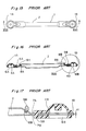
- a known finished link rod 1 subjected to cationic electrodeposition coating is shown in Figs. 15 to 17 and is produced as follows. Initially, each of opposite end portions of a tubular member is crushed over a predetermined distance by stamping and then, is subjected to punching. Thus, a rod having a predetermined length is obtained in which flat sections 1A and 1B are provided at opposite ends of a cylindrical section 2.
- a large-diameter hole 4A and a small-diameter hole 5A are, respectively, formed at outer and inner portions of the flat section 1A by punching, while a large-diameter hole 4B and a small-diameter hole 5B are, respectively, likewise formed at outer and inner portions of the flat section 1B by punching.
- the rod is washed by using cleaning fluid and then, is subjected to cationic electrodeposition coating.
- the flat sections 1A and 1B are inserted into molds and resinous coupling joints 6A and 6B are molded integrally with the opposite ends of the link rod 1, respectively.
- fluid drains 8A and 8B are, respectively, formed at opposite end portions of the cylindrical section 2 adjecent to the flat sections 11A and 11B such that the washing fluid penetrating into the cylindrical section 2 is discharged from the fluid drains 8A and 8B.
- a link rod of a wiper for a motor vehicle comprising a cylindrical section; a pair of flat sections which are, respectively, formed at opposite ends of said cylindrical section by crushing the opposite ends of said cylindrical section from above and below; and a pair of resinous coupling joints which are mounted on said flat sections, respectively; wherein a first hole having a large diameter and a second hole having a small diameter are, respectively, formed at outer and inner portions of each of said flat sections as viewed in a longitudinal direction of said cylindrical section; wherein a gap opens into an axially intermediate portion of a peripheral surface of the second hole such that interior of said cylindrical section is communicated with a mouth of the second hole through the gap; wherein each of said coupling joints includes a joint portion disposed at the first hole and seals the second hole and the gap.
- a method of manufacturing the link rod of the above described arrangement comprising the steps of: crushing each of opposite end portions of a tubular blank over a predetermined length by stamping; punching the opposite end portions of the tubular blank such that a rod body having a pair of flat sections provided at its opposite ends, respectively and a cylindrical section provided between the flat sections; punching a first hole having a large diameter and a second hole having a small diameter at outer and inner portions of each of the flat sections as viewed in a longitudinal direction of the rod body; wherein a gap opens into an axially intermediate portion of a peripheral surface of the second hole such that interior of the cylindrical section is communicated with a mouth of the second hole through the gap; washing the rod body with cleaning fluid; discharging from the mouth of the second hole, the cleaning fluid which has penetrated into the cylindrical section; coating the rod body; and molding a pair of resinous coupling joints integrally with the flat sections, respectively; wherein each of the coupling joints includes a joint portion
- a die formed continuously with a punching bore having a diameter corresponding to that of a punch and a recess disposed above the punching bore and having a diameter larger than that of the punching bore may be employed.
- the gap opens into the axially intermediate portion of the peripheral surface of the small-diameter hole such that interior of the cylindrical section is communicated with the mouth of the small-diameter hole through the gap.
- the resinous coupling joints are molded integrally with the flat sections, respectively so as to seal the gap communicated with the small-diameter hole, namely, seal the cylindrical section.
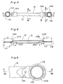
- the link rod K for driving a wiper of a motor vehicle, according to one embodiment of the present invention.
- the link rod K includes flat sections 11A and 11B provided at opposite end portions thereof, a rod body 10 disposed between the flat portions 11A and 11B and resinous coupling joints 13A and 13B molded integrally with opposite ends of the rod body 10, respectively.
- the rod body 10 includes a cylindrical section 12.
- the flat sections 11A and 11B are formed by crushing opposite end portions of the cylindrical section 12.
- the flat section 11A includes an upper plate portion 20A and a lower plate portion 21A.
- the flat section 11B includes an upper plate portion 20B and a lower plate portion 21B.
- the upper plate portions 20A and 20B have a length L1 smaller than a length L2 of the lower plate portions 21A and 21B.
- the upper plate portions 20A and 20B are, respectively, connected with the cylindrical section 12 through oblique portions 22A and 22B, while the lower plate portions 21A and 21B are, respectively, connected with the cylindrical section 12 through oblique portions 23A and 23B.
- a large-diameter hole 14A and a small-diameter hole 15A are, respectively, formed at outer and inner portions of the flat section 11A as viewed in a longitudinal direction of the cylindrical section 12.
- a large-diameter hole 14B and 15B are, respectively, formed at outer and inner portions of the flat section 11B as viewed in the longitudinal direction of the cylindrical section 12.
- the upper and lower plate portions 20B and 21B which constitute the flat section 11B are brought into close contact with each other at a periphery of the large-diameter hole 14B.
- the upper and lower plate portions 20A and 21A of the flat section 11A are also brought into close contact with each other at a periphery of the large-diameter hole 14A.
- a lower mouth of the small-diameter hole 15B projects downwardly from the lower plate portion 21B so as to form a boss 30B by a manufacturing process to be described later such that not only a gap 31B is formed between the upper and lower plate portions 20B and 21B but the gap 31B leads to a gap 32B having a size t2 and communicated with interior of the cylindrical section 12.
- interior of the cylindrical section 12 shown in Fig. 9 is communicated, through the gap 32B shown in Fig. 10, with the mouth of the small-diameter hole 14B and thus, is communicated with exterior of the link rod K. Since the same construction as described above is employed at the other small-diameter hole 15A, description thereof is abbreviated for the sake of brevity.
- the coupling joints 13A and 13B are made of resin and are molded integrally with the flat sections 11A and 11B, respectively.
- the coupling joint 13B includes a joint portion 40B disposed adjacent to the large-diameter hole 14B and a support sealing portion 41B.
- the joint portion 40B is formed by a hemispherical shell and is provided for coupling the joint rod K with another member (not shown ) of the wiper.
- the support sealing portion 41B not only is filled in the small-diameter hole 15B and the gap 31B communicated with the small-diameter hole 15B so as to support the joint portion 40B but seals the cylindrical section 12 from outside. Since the coupling joint 13A has the same construction as the coupling joint 13B, description thereof is abbreviated for the sake of brevity.
- a large-diameter hole 14A and a small-diameter hole 15A are formed at the flat section 11A by punching.
- a large-diameter hole 14B and a small-diameter hole 15B are formed at the flat section 11B by punching.
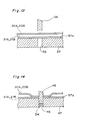
- the small-diameter hole 15A or 15B is formed by punching, it is usually so arranged as shown in Figs. 13 and 14. Namely, the lower plate portion 21A or 21B of the flat section 11A or 11B is placed on an upper face 57a of a die 57 formed with a punching bore 56 having a predetermined diameter. Then, a punch 58 having a diameter corresponding to that of the punching bore 56 is displaced downwardly in Fig. 13 so as to punch the small-diameter hole 15A or 15B. Since diameter of the punching bore 56 is fixed in the axial direction of the punching bore 56, the upper plate portion 20A or 20B is brought into close contact with the lower plate portion 21A or 21B at an outer peripheral portion of the punching bore 56 undesirably.
- a die 50 shown in Figs. 11 and 12 may be employed for forming the small-diameter hole 15A or 15B.
- the die 50 is formed with a stepped bore, i.e. recess 53 formed on an upper face 50a of the die 50 to a predetermined depth T and a punching bore 52 passing through the die 50 coaxially with the recess 53.
- the punching bore 52 has a diameter substantially equal to that of a punch 51, while the recess 53 has a diameter larger than that of the punching bore 52.
- the lower plate portion 20A or 20B of the flat section 11A or 11B is placed on the upper face 50a of the die 50 and then, the punch 51 is depressed downwardly in Fig. 11.
- the upper plate portion 20A or 20B and the lower plate portion 21A or 21B are bent into the recess 53 at an edge 53a of the recess 53.
- a central part of each of the bent portions of the upper plate portions 20A or 20B and the lower plate portions 21A or 21B is sheared by the punch 51 and the punching bore 52 so as to be discharged, as a punching residue 54, out of the punching bore 52.
- the small-diameter hole 15A or 15B is formed.
- each of the upper plate portion 20A or 20B and the lower plate portion 21A or 21B is bent into the recess 53 at a periphery of the small-diameter hole 15A or 15B.
- the boss 30A or 30B is formed on the lower plate portion 21A or 21B.
- the gap 31A or 31B opening into the small-diameter hole 15A or 15B and the gap 32A or 32B connecting the gap 31A or 31B with interior of the cylindrical section 12 can be secured.
- the rod body 10 When the rod body 10 has been formed, the rod body 10 is washed such that oil, etc. used during punching are removed from the rod body 10.
- the cleaning fluid in the cylindrical section 12 can be easily discharged from the small-diameter hole 15A or 15B through the gap 32A or 32B and the gap 31A or 31B.
- a period required for discharging the cleaning fluid from the cylindrical section 12 is usually about 30 sec. Therefore, in the manufacturing method deterioration, etc. of coating fluid caused by flow of the cleaning fluid into the coating fluid can be easily prevented.
- the rod body 10 is subjected to cationic electrodeposition coating.
- the coating fluid, hot water, etc. flow into the cylindrical section 12, the coating fluid, hot water, etc. can be easily and rapidly discharged from the small-diameter holes 15A and 15B.
- the resinous coupling joints 13A and 13B are molded integrally with the flat sections 11A and 11B.
- resin forming the coupling joints 13A and 13B closes the gaps 32A and 32B so as to seal interior of the cylindrical section 12. Meanwhile, such a phenomenon may happen in which the gaps 32A and 32B are closed by clamping force of molds used at the time of integral molding of the coupling joints 13A and 13B.
- a special discharge hole for discharging liquid in the cylindrical section is not provided and a plug member for closing the discharge hole are not required to be provided. Therefore, in the manufacturing method a process of forming the discharge liquid and a process of closing the discharge hole can be eliminated in contrast with a known manufacturing method.
- the link rod is simplified structurally.
- the cleaning fluid, etc. can be discharged from the cylindrical section easily and rapidly, deterioration, etc. of the coating fluid can be prevented easily.
- the process of forming the discharge hole and the process of closing the discharge hole can be eliminated, thereby resulting in reduction of manufacturing cost of the link rod.
Landscapes
- Engineering & Computer Science (AREA)
- General Engineering & Computer Science (AREA)
- Mechanical Engineering (AREA)
- Shafts, Cranks, Connecting Bars, And Related Bearings (AREA)
- Manufacture Of Motors, Generators (AREA)
- Pivots And Pivotal Connections (AREA)
Applications Claiming Priority (2)
| Application Number | Priority Date | Filing Date | Title |
|---|---|---|---|
| JP3129739A JP2536977B2 (ja) | 1991-05-31 | 1991-05-31 | 自動車用ワイパ―の連結継手及びその製造方法 |
| JP129739/91 | 1991-05-31 |
Publications (2)
| Publication Number | Publication Date |
|---|---|
| EP0517436A1 true EP0517436A1 (de) | 1992-12-09 |
| EP0517436B1 EP0517436B1 (de) | 1994-09-21 |
Family
ID=15017013
Family Applications (1)
| Application Number | Title | Priority Date | Filing Date |
|---|---|---|---|
| EP92304886A Expired - Lifetime EP0517436B1 (de) | 1991-05-31 | 1992-05-29 | Verbindungsstange für Kraftfahrzeugscheibenwischer und Verfahren zu ihrer Herstellung |
Country Status (4)
| Country | Link |
|---|---|
| EP (1) | EP0517436B1 (de) |
| JP (1) | JP2536977B2 (de) |
| CA (1) | CA2069586C (de) |
| DE (1) | DE69200435T2 (de) |
Cited By (8)
| Publication number | Priority date | Publication date | Assignee | Title |
|---|---|---|---|---|
| WO1995017324A1 (en) * | 1993-12-23 | 1995-06-29 | United Technologies Automotive, Inc. | Connecting links for windshield wipers and method for fabricating the link |
| EP0670252A1 (de) * | 1994-03-03 | 1995-09-06 | Valeo Systemes D'essuyage | Befestigungsteil für einen Scheibenwischer eines Kraftfahrzeuges |
| EP0851131A3 (de) * | 1996-12-26 | 1999-10-13 | Tenneco Automotive Inc. | Stahlverstärkter gefüllter Polymerdrehstab |
| FR2777846A1 (fr) * | 1998-04-23 | 1999-10-29 | Jidosha Denki Kogyo Kk | Tige de liaison articulee pour un dispositif d'essuie-glace |
| WO2009127748A1 (es) * | 2008-04-18 | 2009-10-22 | Doga S.A. | Biela para mecanismo de limpiaparabrisas |
| CN102554081A (zh) * | 2011-12-31 | 2012-07-11 | 广东亚太不锈钢制品有限公司 | 一种高强度、高硬度、高棱边直度汽车雨刮线的生产方法 |
| WO2013050219A1 (de) * | 2011-10-07 | 2013-04-11 | Zf Friedrichshafen Ag | Verbindungsbauteil für ein fahrzeug |
| CN103448681A (zh) * | 2012-05-30 | 2013-12-18 | 罗伯特·博世有限公司 | 用于窗玻璃刮水装置的刮水器连杆中的铰链杆 |
Families Citing this family (2)
| Publication number | Priority date | Publication date | Assignee | Title |
|---|---|---|---|---|
| KR101180942B1 (ko) * | 2009-12-04 | 2012-09-07 | 현대자동차주식회사 | 서스펜션 암 |
| JP5923154B2 (ja) * | 2014-10-28 | 2016-05-24 | 日本発條株式会社 | リンクアーム部材 |
Citations (3)
| Publication number | Priority date | Publication date | Assignee | Title |
|---|---|---|---|---|
| FR1508265A (fr) * | 1966-11-22 | 1968-01-05 | Ducellier & Cie | élément d'embiellage, notamment bielle pour tringlerie d'essuie-glace |
| FR2385935A1 (fr) * | 1977-04-01 | 1978-10-27 | Aerospatiale | Procede permettant la realisation d'un embout fixe pour une bielle de commande, et bielle ainsi obtenue |
| DE3843330A1 (de) * | 1988-12-22 | 1990-07-05 | Ishikawa Tekko Kk | Einsatzgiessartikel |
-
1991
- 1991-05-31 JP JP3129739A patent/JP2536977B2/ja not_active Expired - Lifetime
-
1992
- 1992-05-26 CA CA002069586A patent/CA2069586C/en not_active Expired - Lifetime
- 1992-05-29 DE DE69200435T patent/DE69200435T2/de not_active Expired - Lifetime
- 1992-05-29 EP EP92304886A patent/EP0517436B1/de not_active Expired - Lifetime
Patent Citations (3)
| Publication number | Priority date | Publication date | Assignee | Title |
|---|---|---|---|---|
| FR1508265A (fr) * | 1966-11-22 | 1968-01-05 | Ducellier & Cie | élément d'embiellage, notamment bielle pour tringlerie d'essuie-glace |
| FR2385935A1 (fr) * | 1977-04-01 | 1978-10-27 | Aerospatiale | Procede permettant la realisation d'un embout fixe pour une bielle de commande, et bielle ainsi obtenue |
| DE3843330A1 (de) * | 1988-12-22 | 1990-07-05 | Ishikawa Tekko Kk | Einsatzgiessartikel |
Cited By (13)
| Publication number | Priority date | Publication date | Assignee | Title |
|---|---|---|---|---|
| WO1995017324A1 (en) * | 1993-12-23 | 1995-06-29 | United Technologies Automotive, Inc. | Connecting links for windshield wipers and method for fabricating the link |
| US5522280A (en) * | 1993-12-23 | 1996-06-04 | United Technologies Motor Systems, Inc. | Connecting links for windshield wipers and method for fabricating the link |
| EP0670252A1 (de) * | 1994-03-03 | 1995-09-06 | Valeo Systemes D'essuyage | Befestigungsteil für einen Scheibenwischer eines Kraftfahrzeuges |
| FR2716852A1 (fr) * | 1994-03-03 | 1995-09-08 | Valeo Systemes Dessuyage | Essuie-glace de véhicule automobile comportant une tête d'entraînement perfectionnée. |
| EP0851131A3 (de) * | 1996-12-26 | 1999-10-13 | Tenneco Automotive Inc. | Stahlverstärkter gefüllter Polymerdrehstab |
| GB2337801A (en) * | 1998-04-23 | 1999-12-01 | Jidosha Denki Kogyo Kk | Link Rod For Wiper apparatus |
| FR2777846A1 (fr) * | 1998-04-23 | 1999-10-29 | Jidosha Denki Kogyo Kk | Tige de liaison articulee pour un dispositif d'essuie-glace |
| GB2337801B (en) * | 1998-04-23 | 2001-11-21 | Jidosha Denki Kogyo Kk | Link connecting rod for wiper apparatus |
| WO2009127748A1 (es) * | 2008-04-18 | 2009-10-22 | Doga S.A. | Biela para mecanismo de limpiaparabrisas |
| WO2013050219A1 (de) * | 2011-10-07 | 2013-04-11 | Zf Friedrichshafen Ag | Verbindungsbauteil für ein fahrzeug |
| CN102554081A (zh) * | 2011-12-31 | 2012-07-11 | 广东亚太不锈钢制品有限公司 | 一种高强度、高硬度、高棱边直度汽车雨刮线的生产方法 |
| CN103448681A (zh) * | 2012-05-30 | 2013-12-18 | 罗伯特·博世有限公司 | 用于窗玻璃刮水装置的刮水器连杆中的铰链杆 |
| CN103448681B (zh) * | 2012-05-30 | 2017-04-12 | 罗伯特·博世有限公司 | 用于窗玻璃刮水装置的刮水器连杆中的铰链杆 |
Also Published As
| Publication number | Publication date |
|---|---|
| EP0517436B1 (de) | 1994-09-21 |
| DE69200435D1 (de) | 1994-10-27 |
| CA2069586A1 (en) | 1992-12-01 |
| JP2536977B2 (ja) | 1996-09-25 |
| DE69200435T2 (de) | 1995-05-04 |
| CA2069586C (en) | 1997-03-25 |
| JPH04356256A (ja) | 1992-12-09 |
Similar Documents
| Publication | Publication Date | Title |
|---|---|---|
| US5213008A (en) | Link rod of wiper for motor vehicle and method of manufacturing the same | |
| EP0517436B1 (de) | Verbindungsstange für Kraftfahrzeugscheibenwischer und Verfahren zu ihrer Herstellung | |
| CA2224350C (en) | Gasket insert and method of making same | |
| US6803146B2 (en) | Battery terminal and method for making the same | |
| US6079715A (en) | Rotary shaft seal having a PTFE seal lip and a method and apparatus of manufacturing same | |
| US6341983B1 (en) | Co-molded seal and strain relief for automotive electrical connections | |
| DE102007040848A1 (de) | Wärmeaustauscher und Verfahren zu seiner Herstellung | |
| DE10012169B4 (de) | Druckerfassungsvorrichtung, Verfahren zu deren Herstellung und Gießvorrichtung | |
| EP2122784B1 (de) | Sensoranordnung | |
| EP0695624A1 (de) | Tankanschlussteilkonstruktion | |
| EP0747623A1 (de) | Verfahren zum Herstellen eines Behälters und eines Behälteranschlusses dafür | |
| EP0747622A1 (de) | Behälteranschluss | |
| CA2124096C (en) | Meltable core | |
| KR100537846B1 (ko) | 하우징 블록 | |
| US4429718A (en) | Pressure resistant accumulator device | |
| US5431764A (en) | Method of fabricating a tank and method of fabricating a tank connector therefor | |
| EP0687547A2 (de) | Behälter | |
| US4506431A (en) | Method of making pressure resistant accumulator device | |
| DE3144176A1 (de) | Druckgefaess, insbesondere hydrospeicher, und verfahren zu seiner herstellung | |
| US20020134194A1 (en) | Axle housing cover with variable thickness | |
| CA2633706A1 (en) | Differential housing and production method | |
| KR100215240B1 (ko) | 자동차 조향장치용 멀티 스텝 유니버셜조인트 | |
| IT8548738A1 (it) | Procedimento per la produzione di un elemento di raccordo per le tubazioni di adduzione e di scarico di panelli radianti | |
| JP2757503B2 (ja) | ホース用継手 | |
| JPS5838350B2 (ja) | 板金製品の穴封じ方法 |
Legal Events
| Date | Code | Title | Description |
|---|---|---|---|
| PUAI | Public reference made under article 153(3) epc to a published international application that has entered the european phase |
Free format text: ORIGINAL CODE: 0009012 |
|
| AK | Designated contracting states |
Kind code of ref document: A1 Designated state(s): DE FR GB |
|
| 17P | Request for examination filed |
Effective date: 19921218 |
|
| 17Q | First examination report despatched |
Effective date: 19940118 |
|
| GRAA | (expected) grant |
Free format text: ORIGINAL CODE: 0009210 |
|
| AK | Designated contracting states |
Kind code of ref document: B1 Designated state(s): DE FR GB |
|
| REF | Corresponds to: |
Ref document number: 69200435 Country of ref document: DE Date of ref document: 19941027 |
|
| ET | Fr: translation filed | ||
| PLBE | No opposition filed within time limit |
Free format text: ORIGINAL CODE: 0009261 |
|
| STAA | Information on the status of an ep patent application or granted ep patent |
Free format text: STATUS: NO OPPOSITION FILED WITHIN TIME LIMIT |
|
| 26N | No opposition filed | ||
| REG | Reference to a national code |
Ref country code: GB Ref legal event code: IF02 |
|
| PGFP | Annual fee paid to national office [announced via postgrant information from national office to epo] |
Ref country code: FR Payment date: 20110523 Year of fee payment: 20 |
|
| PGFP | Annual fee paid to national office [announced via postgrant information from national office to epo] |
Ref country code: GB Payment date: 20110525 Year of fee payment: 20 |
|
| PGFP | Annual fee paid to national office [announced via postgrant information from national office to epo] |
Ref country code: DE Payment date: 20110525 Year of fee payment: 20 |
|
| REG | Reference to a national code |
Ref country code: DE Ref legal event code: R071 Ref document number: 69200435 Country of ref document: DE |
|
| REG | Reference to a national code |
Ref country code: DE Ref legal event code: R071 Ref document number: 69200435 Country of ref document: DE |
|
| REG | Reference to a national code |
Ref country code: GB Ref legal event code: PE20 Expiry date: 20120528 |
|
| PG25 | Lapsed in a contracting state [announced via postgrant information from national office to epo] |
Ref country code: DE Free format text: LAPSE BECAUSE OF EXPIRATION OF PROTECTION Effective date: 20120530 |
|
| PG25 | Lapsed in a contracting state [announced via postgrant information from national office to epo] |
Ref country code: GB Free format text: LAPSE BECAUSE OF EXPIRATION OF PROTECTION Effective date: 20120528 |