EP0517759B1 - Procede de mesure d'une boue liquide - Google Patents
Procede de mesure d'une boue liquide Download PDFInfo
- Publication number
- EP0517759B1 EP0517759B1 EP91904981A EP91904981A EP0517759B1 EP 0517759 B1 EP0517759 B1 EP 0517759B1 EP 91904981 A EP91904981 A EP 91904981A EP 91904981 A EP91904981 A EP 91904981A EP 0517759 B1 EP0517759 B1 EP 0517759B1
- Authority
- EP
- European Patent Office
- Prior art keywords
- fluid
- measuring
- light source
- rinsing
- radiation
- Prior art date
- Legal status (The legal status is an assumption and is not a legal conclusion. Google has not performed a legal analysis and makes no representation as to the accuracy of the status listed.)
- Expired - Lifetime
Links
- 238000000034 method Methods 0.000 title claims abstract description 15
- 239000002002 slurry Substances 0.000 title claims abstract description 10
- 230000005855 radiation Effects 0.000 claims abstract description 40
- 239000012530 fluid Substances 0.000 claims abstract description 25
- 238000011156 evaluation Methods 0.000 claims abstract description 6
- 239000005416 organic matter Substances 0.000 claims description 4
- 238000005259 measurement Methods 0.000 claims description 3
- 229910052736 halogen Inorganic materials 0.000 claims description 2
- 150000002367 halogens Chemical class 0.000 claims description 2
- 229910052724 xenon Inorganic materials 0.000 claims description 2
- FHNFHKCVQCLJFQ-UHFFFAOYSA-N xenon atom Chemical compound [Xe] FHNFHKCVQCLJFQ-UHFFFAOYSA-N 0.000 claims description 2
- 230000005540 biological transmission Effects 0.000 claims 1
- 238000004140 cleaning Methods 0.000 description 5
- 239000010802 sludge Substances 0.000 description 5
- XLYOFNOQVPJJNP-UHFFFAOYSA-N water Substances O XLYOFNOQVPJJNP-UHFFFAOYSA-N 0.000 description 4
- 230000000155 isotopic effect Effects 0.000 description 3
- 238000013016 damping Methods 0.000 description 2
- 239000011796 hollow space material Substances 0.000 description 2
- 238000007789 sealing Methods 0.000 description 2
- 230000002238 attenuated effect Effects 0.000 description 1
- 230000000903 blocking effect Effects 0.000 description 1
- 238000011088 calibration curve Methods 0.000 description 1
- 239000004020 conductor Substances 0.000 description 1
- 230000005670 electromagnetic radiation Effects 0.000 description 1
- 238000011010 flushing procedure Methods 0.000 description 1
- 229910001385 heavy metal Inorganic materials 0.000 description 1
- 238000007654 immersion Methods 0.000 description 1
- 230000003287 optical effect Effects 0.000 description 1
- 239000008237 rinsing water Substances 0.000 description 1
- 239000000523 sample Substances 0.000 description 1
- 238000002604 ultrasonography Methods 0.000 description 1
Images

Classifications
-
- G—PHYSICS
- G01—MEASURING; TESTING
- G01N—INVESTIGATING OR ANALYSING MATERIALS BY DETERMINING THEIR CHEMICAL OR PHYSICAL PROPERTIES
- G01N21/00—Investigating or analysing materials by the use of optical means, i.e. using sub-millimetre waves, infrared, visible or ultraviolet light
- G01N21/84—Systems specially adapted for particular applications
- G01N21/85—Investigating moving fluids or granular solids
- G01N21/8507—Probe photometers, i.e. with optical measuring part dipped into fluid sample
-
- G—PHYSICS
- G01—MEASURING; TESTING
- G01N—INVESTIGATING OR ANALYSING MATERIALS BY DETERMINING THEIR CHEMICAL OR PHYSICAL PROPERTIES
- G01N21/00—Investigating or analysing materials by the use of optical means, i.e. using sub-millimetre waves, infrared, visible or ultraviolet light
- G01N21/01—Arrangements or apparatus for facilitating the optical investigation
- G01N21/15—Preventing contamination of the components of the optical system or obstruction of the light path
Definitions
- the invention relates to a method of continuously determining the parameters of a fluid, such as the dry-matter percentage in slurry or another industrial product, and whereby said fluid is subjected to a measuring system comprising a radiation source and a radiation detector placed opposite one another, the measuring signals being processed in an evaluation circuit, wherafter the results of the evaluation are displayed on display means.
- a measuring system comprising a radiation source and a radiation detector placed opposite one another, the measuring signals being processed in an evaluation circuit, wherafter the results of the evaluation are displayed on display means.
- a system for measuring parameter values of a passing fluid.
- the system comprises a radiation source and a radiation detector optionally in direct contact with the fluid.
- Means may furthermore be provided for cleaning the radiation source and the radiation detector.
- Such means may for instance be in form of a scraper or a jet of wash water, cf. US patent specification No. 4,896,047.
- Such systems are encumbered with the drawback that it is impossible to maintain clean surfaces and to clean said surfaces to the same extent each time. Accordingly, it is impossible to achieve correct measuring values.
- the apparatus comprises a sensing head for immersion in the fluid.
- the sensing head has two optical windows which are placed opposite one another in a hollow space having access from both sides so as to allow the fluid to penetrate into the hollow space.
- the sensing head requires a cleaning of the windows followed by a calibration.
- the calibration consists of a calibration in an almost pure fluid followed by a calibration with a mechanical interruption of the path of radiation. After that the calibration curve can be determined, and compensation may be made by means of a computer.
- a disadvantage of this apparatus is that the sensing head is relatively complicated and that it requires several fluid controlling systems and a mecanical blocking of the path of radiation.
- the object of the invention is to provide a method solving the above problems.
- the method according to the invention is characterised in that the radiation source and the radiation detector are mounted on a forked support immersible in the fluid in question.
- the measuring signal may be subjected to a simultaneous/following calibration, the source and the detector being subjected to a rinsing.
- the radiation used may for instance be provided by light, sound or soft isotopic radiation.
- the invention refers to highly polluted fluids, such as sludge.
- An interest has arisen in measuring the dry-matter percentage relative to the water percentage in slurry.
- the measuring may for instance be carried out by measuring the damping of a suitably selected radiation light, sound or isotopic radiation over a predetermined measuring length.
- a problem applies, however, because the radiation source and the radiation detector are polluted on the surface with the result that the measuring signal is degraded.
- the sludge passes a pipe 1 provided with two opposing transducers 2, 3 flushing with the inner side of said pipe 1.
- the inner side of the transducers 2, 3 are kept clean by means of a rotating, cylindrical scraper 4 comprising V-shaped notches.
- the rotation of the scraper 4 is caused by means of an outer gear wheel engaging said cylindrical, rotating scraper 4 through a slot in the pipe 1.
- Such a system is, however, encumbered with sealing problems.
- the scraper 4 may also be formed such that it is caused to rotate by the passing sludge, and then it is provided with inner fins.
- the scraper 4 can be made of an electrically conductive material and caused to rotate by means of an electromagnetic, rotating field applied from the outside by means of electromagnets 5 placed on the outside, whereby sealing problems are avoided.
- Permanent magnets may furthermore be embedded in the rotating scraper 4, said permanent magnets being caused to follow the rotating field.
- the rotating scraper is provided with inner fins, the permanent magnets may be used for indicating the flow velocity with the result that it is possible in addition to achieve a measurement of the viscosity which may also be of interest.
- the rotating scraper 22 has been inserted from the side perpendicular to said embodiment.
- the T-model is advantageous in facilitating the providing of a rotation by means of a motor 6.
- the rotating scraper 22 need only be mounted in a liquid-proof manner relative to the motor 6.
- the driving shaft 21 of the rotating scraper 22 extends through a housing via a liquid-proof bearing, said housing sealingly surrounding the pipe.
- the transducers 7, 7′ are preferably ultrasonic transducers.
- portions of the rotating scraper or a particularly shaped member mounted thereon may be used for calibration.
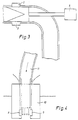
- the radiation source 8 and the radiation detector 9 are mounted on a forked support 10 immersible in the fluid to be measured. Before the calibration, the detector 8 and the radiation source 9 are rinsed by means of rinsing water being fed through a channel 11 in the forked support 10.
- the channel 11 may optinally split up into two branch pipes, one branch pipe facing the radiation source 8 and the other branch pipe facing the radiation detector 9.
- the feeding hose 14 to the channel 11 is provided with a valve controlling the supply of water.
- the radiation source 8 is spaced approximately 10 mm from the radiation detector 9. According to the invention a reference measurement is performed, i.e.
- the rinsing channel fills the entire space between the detector 9 and the source 8 with the result that the rinsing fluid functions as a reference fluid because said rinsing fluid fills the entire volume between the radiation source 8 and the radiation detector 9.
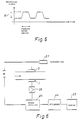
- Fig. 5 illustrates an example of measuring signals.
- Fig. 6 illustrates an example of the electronic circuit in question, where the transmitter 21 communicates with the transmitter-transducer 2.
- the signal received by the receiver-transducer 3 is transmitted to an amplifier 26 in turn transmitting said signal to an amplitude and phase detector 23. Subsequently, the signal is processed in a microprocessor circuit 24 connected to a display 25.
- the radiation in question is not necessarily ultrasound. Alternatively, it may be an electromagnetic radiation, such as light or a soft isotopic radiation when heavy metals are to be measured.
- the measuring value is compared with the reference value provided at the end of the cleaning process because said comparing turned out to provide sufficiently good measuring results.
- the measuring method is in particular used for measuring the dry-matter percentage in sludge by means of infrared light.
- the method can, however, also be used for other measurings of parameter values of a fluid.
- the light used is infrared and ultraviolet light.
- the ultraviolet light is attenuated in response to the amount of organic matter (BOD,COD).
- BOD,COD organic matter
- the ratio of infrared to ultraviolet damping is related to the amount of organic matter. Accordingly, a measuring of the attenuation of ultraviolet light relative to infrared light results in the percentage of organic matter in for instance sludge.
- the radiation source for emission of both ultraviolet and infrared light may for instance be a halogen or a xenon lamp.
- the receiving side is provided with a separate detector for infrared light and separate detector for ultraviolet light.
- the radiation source may be adapted to pulsed operation.
Landscapes
- Physics & Mathematics (AREA)
- Health & Medical Sciences (AREA)
- Life Sciences & Earth Sciences (AREA)
- Chemical & Material Sciences (AREA)
- Analytical Chemistry (AREA)
- Biochemistry (AREA)
- General Health & Medical Sciences (AREA)
- General Physics & Mathematics (AREA)
- Immunology (AREA)
- Pathology (AREA)
- Analysing Materials By The Use Of Radiation (AREA)
- Investigating Or Analysing Materials By Optical Means (AREA)
- Organic Low-Molecular-Weight Compounds And Preparation Thereof (AREA)
- Investigating Or Analyzing Materials Using Thermal Means (AREA)
Claims (6)
- Procédé pour la détermination en continu des paramètres d'un fluide, tels que le pourcentage en matière sèche dans la boue dans un produit industriel, ce fluide étant soumis à un système de mesure comprenant une source lumineuse et un détecteur lumineux monté sur un support en forme de fourche en regard l'un de l'autre de façon à définir un espace de mesure, les signaux de mesure étant traités dans un circuit d'évaluation, après quoi les résultats de l'évaluation sont affichés sur des moyens d'affichage, le procédé comprenant les étapes consistant à immerger le support en forme de fourche dans le fluide, après quoi l'espace de mesure est soumis à une période de rinçage en laissant entrer un fluide de rinçage pour remplir la totalité de l'espace par l'intermédiaire d'un canal de rinçage, la fin de cette période de rinçage étant consacrée à l'étalonnage selon lequel ce fluide de rinçage agit comme fluide de référence, après quoi, pendant la mesure, le signal de mesure réel est comparé au signal de référence formé pendant l'étalonnage.
- Procédé selon la revendication 1, caractérisé en ce que la source lumineuse est une source lumineuse infrarouge.
- Procédé selon la revendication 1, caractérisé en ce que la source lumineuse est une source lumineuse ultraviolette.
- Procédé selon la revendication 2 et 3, caractérisé en ce que l'on mesure le rapport de transmission de la lumière ultraviolette à la lumière infrarouge de façon à déterminer le pourcentage de matière organique.
- Procédé selon la revendication 2, 3 ou 4, caractérisé en ce que la source lumineuse émettant à la fois la lumière ultraviolette et la lumière infrarouge et une lampe halogène ou xénon.
- Procédé selon l'une quelconque des revendications précédentes, caractérisé par le fait d'utiliser une radiation à lumière pulsée.
Applications Claiming Priority (3)
| Application Number | Priority Date | Filing Date | Title |
|---|---|---|---|
| DK503/90 | 1990-02-26 | ||
| DK050390A DK170351B1 (da) | 1990-02-26 | 1990-02-26 | Fremgangsmåde til kontinuerlig bestemmelse af parametre af et fluidum |
| PCT/DK1991/000053 WO1991013340A1 (fr) | 1990-02-26 | 1991-02-21 | Procede de mesure d'une boue liquide |
Publications (2)
| Publication Number | Publication Date |
|---|---|
| EP0517759A1 EP0517759A1 (fr) | 1992-12-16 |
| EP0517759B1 true EP0517759B1 (fr) | 1995-11-08 |
Family
ID=8094305
Family Applications (1)
| Application Number | Title | Priority Date | Filing Date |
|---|---|---|---|
| EP91904981A Expired - Lifetime EP0517759B1 (fr) | 1990-02-26 | 1991-02-21 | Procede de mesure d'une boue liquide |
Country Status (6)
| Country | Link |
|---|---|
| EP (1) | EP0517759B1 (fr) |
| AT (1) | ATE130091T1 (fr) |
| AU (1) | AU7337791A (fr) |
| DE (1) | DE69114484T2 (fr) |
| DK (1) | DK170351B1 (fr) |
| WO (1) | WO1991013340A1 (fr) |
Cited By (1)
| Publication number | Priority date | Publication date | Assignee | Title |
|---|---|---|---|---|
| DE202016106236U1 (de) * | 2016-11-08 | 2018-02-09 | Hach Lange Gmbh | Optisches Messgerät |
Families Citing this family (4)
| Publication number | Priority date | Publication date | Assignee | Title |
|---|---|---|---|---|
| SE9101259D0 (sv) * | 1991-04-25 | 1991-04-25 | Fladda Mcs Ab | Metod foer att kompensera foer ljusintensitetsfoeraendringar i ett optiskt maetgap vid bestaemning av halten suspenderat material |
| WO2004068127A1 (fr) * | 2003-01-31 | 2004-08-12 | L'air Liquide - Societe Anonyme A Directoire Et Conseil De Surveillance Pour L'etude Et L'exploitation Des Procedes Georges Claude | Procede et dispositif permettant de controler la consistance d'une suspension epaisse |
| SE530500C2 (sv) * | 2006-11-16 | 2008-06-24 | Delaval Holding Ab | Anordning och förfarande för provtagning av mjölk |
| CN119715290B (zh) * | 2023-09-28 | 2025-09-30 | 中国石油天然气股份有限公司 | 一种填砂管泥浆污染实验装置及方法 |
Family Cites Families (5)
| Publication number | Priority date | Publication date | Assignee | Title |
|---|---|---|---|---|
| US4040743A (en) * | 1975-09-22 | 1977-08-09 | Howell Laboratories, Incorporated | Method and apparatus for measuring the brightness of pulp slurry |
| US4201477A (en) * | 1978-01-16 | 1980-05-06 | Fmc Corporation | Suspended solids meter |
| JPS5923378B2 (ja) * | 1979-05-17 | 1984-06-01 | 株式会社東芝 | 濃度計 |
| JPS56153242A (en) * | 1980-04-30 | 1981-11-27 | Fuji Electric Co Ltd | Measuring device for organic pollution component contained in water |
| JPH02501677A (ja) * | 1987-10-15 | 1990-06-07 | エレクトロニック・インストルメンテーション・アンド・テクノロジー・インコーポレーテッド | 溶液成分分析装置 |
-
1990
- 1990-02-26 DK DK050390A patent/DK170351B1/da not_active IP Right Cessation
-
1991
- 1991-02-21 AT AT91904981T patent/ATE130091T1/de active
- 1991-02-21 DE DE69114484T patent/DE69114484T2/de not_active Expired - Fee Related
- 1991-02-21 AU AU73377/91A patent/AU7337791A/en not_active Abandoned
- 1991-02-21 WO PCT/DK1991/000053 patent/WO1991013340A1/fr not_active Ceased
- 1991-02-21 EP EP91904981A patent/EP0517759B1/fr not_active Expired - Lifetime
Cited By (1)
| Publication number | Priority date | Publication date | Assignee | Title |
|---|---|---|---|---|
| DE202016106236U1 (de) * | 2016-11-08 | 2018-02-09 | Hach Lange Gmbh | Optisches Messgerät |
Also Published As
| Publication number | Publication date |
|---|---|
| ATE130091T1 (de) | 1995-11-15 |
| DK50390D0 (da) | 1990-02-26 |
| DK50390A (da) | 1991-08-27 |
| EP0517759A1 (fr) | 1992-12-16 |
| DK170351B1 (da) | 1995-08-07 |
| DE69114484T2 (de) | 1996-07-18 |
| DE69114484D1 (de) | 1995-12-14 |
| AU7337791A (en) | 1991-09-18 |
| WO1991013340A1 (fr) | 1991-09-05 |
Similar Documents
| Publication | Publication Date | Title |
|---|---|---|
| AU652553B2 (en) | Turbidity measurement | |
| US5471872A (en) | Acoustic liquid level measuring apparatus | |
| EP2105737A1 (fr) | Système de détection des défauts dans une paroi de tuyau par ultrasons | |
| KR900001575B1 (ko) | 액중 이물류의 계측방법 | |
| US5684252A (en) | Method and apparatus for ultrasonic inspection of electronic components | |
| US5459568A (en) | Concentration measuring apparatus | |
| CA2429063A1 (fr) | Dispositif et methode de mesure sur place en temps reel des proprietes des liquides | |
| JPS6256842A (ja) | 流体の品質を赤外線を用いて電気光学的に分析する方法及び装置 | |
| EP0517759B1 (fr) | Procede de mesure d'une boue liquide | |
| JP2686026B2 (ja) | 導管の内側に蓄積された薄層の厚みを決定する方法および装置 | |
| EP0833151A3 (fr) | Dispositif de mesure de la qualité de points de soudure | |
| CN104111237B (zh) | 用于光学地测量介质的一种或更多种物理、化学和/或生物学过程变量的布置 | |
| CA2241875A1 (fr) | Procede et dispositif pour determiner le niveau d'un liquide a l'aide d'impulsions ultrasonores | |
| US4201477A (en) | Suspended solids meter | |
| EP1305596B1 (fr) | Procede et systeme de mesure de turbidité | |
| US4940902A (en) | Apparatus and method for continuous measurement of suspended solids in a liquid medium with wiping means | |
| EP0050452B1 (fr) | Appareil d'indication de variations dans les propriétés acoustiques d'une interface | |
| KR101927673B1 (ko) | 데드존 센서를 구비한 수위 측정 장치 | |
| JP3271459B2 (ja) | 浸漬型光学センサとその自動校正方法 | |
| GB2284053A (en) | Detecting presence or absence of liquid in a vessel | |
| JPH1019764A (ja) | 濃度計測装置 | |
| EP1014048A3 (fr) | Dispositif d'indication du niveau de liquide dans un réservoir | |
| JPS5934135A (ja) | 光学式水質測定装置 | |
| JPH10122936A (ja) | 界面計 | |
| JPH06197893A (ja) | 超音波透過検査装置 |
Legal Events
| Date | Code | Title | Description |
|---|---|---|---|
| PUAI | Public reference made under article 153(3) epc to a published international application that has entered the european phase |
Free format text: ORIGINAL CODE: 0009012 |
|
| 17P | Request for examination filed |
Effective date: 19920810 |
|
| AK | Designated contracting states |
Kind code of ref document: A1 Designated state(s): AT BE CH DE DK ES FR GB GR IT LI LU NL SE |
|
| 17Q | First examination report despatched |
Effective date: 19940919 |
|
| GRAA | (expected) grant |
Free format text: ORIGINAL CODE: 0009210 |
|
| AK | Designated contracting states |
Kind code of ref document: B1 Designated state(s): AT BE CH DE DK ES FR GB GR IT LI LU NL SE |
|
| PG25 | Lapsed in a contracting state [announced via postgrant information from national office to epo] |
Ref country code: BE Effective date: 19951108 Ref country code: IT Free format text: LAPSE BECAUSE OF FAILURE TO SUBMIT A TRANSLATION OF THE DESCRIPTION OR TO PAY THE FEE WITHIN THE PRE;WARNING: LAPSES OF ITALIAN PATENTS WITH EFFECTIVE DATE BEFORE 2007 MAY HAVE OCCURRED AT ANY TIME BEFORE 2007. THE CORRECT EFFECTIVE DATE MAY BE DIFFERENT FROM THE ONE RECORDED.SCRIBED TIME-LIMIT Effective date: 19951108 Ref country code: LI Effective date: 19951108 Ref country code: NL Free format text: LAPSE BECAUSE OF FAILURE TO SUBMIT A TRANSLATION OF THE DESCRIPTION OR TO PAY THE FEE WITHIN THE PRESCRIBED TIME-LIMIT Effective date: 19951108 Ref country code: AT Effective date: 19951108 Ref country code: DK Effective date: 19951108 Ref country code: CH Effective date: 19951108 Ref country code: GR Free format text: LAPSE BECAUSE OF FAILURE TO SUBMIT A TRANSLATION OF THE DESCRIPTION OR TO PAY THE FEE WITHIN THE PRESCRIBED TIME-LIMIT Effective date: 19951108 Ref country code: ES Free format text: THE PATENT HAS BEEN ANNULLED BY A DECISION OF A NATIONAL AUTHORITY Effective date: 19951108 |
|
| REF | Corresponds to: |
Ref document number: 130091 Country of ref document: AT Date of ref document: 19951115 Kind code of ref document: T |
|
| REF | Corresponds to: |
Ref document number: 69114484 Country of ref document: DE Date of ref document: 19951214 |
|
| PG25 | Lapsed in a contracting state [announced via postgrant information from national office to epo] |
Ref country code: SE Effective date: 19960208 |
|
| PG25 | Lapsed in a contracting state [announced via postgrant information from national office to epo] |
Ref country code: LU Free format text: LAPSE BECAUSE OF NON-PAYMENT OF DUE FEES Effective date: 19960229 |
|
| ET | Fr: translation filed | ||
| NLV1 | Nl: lapsed or annulled due to failure to fulfill the requirements of art. 29p and 29m of the patents act | ||
| REG | Reference to a national code |
Ref country code: CH Ref legal event code: PL |
|
| PLBE | No opposition filed within time limit |
Free format text: ORIGINAL CODE: 0009261 |
|
| STAA | Information on the status of an ep patent application or granted ep patent |
Free format text: STATUS: NO OPPOSITION FILED WITHIN TIME LIMIT |
|
| 26N | No opposition filed | ||
| PGFP | Annual fee paid to national office [announced via postgrant information from national office to epo] |
Ref country code: FR Payment date: 19990210 Year of fee payment: 9 |
|
| PGFP | Annual fee paid to national office [announced via postgrant information from national office to epo] |
Ref country code: GB Payment date: 19990212 Year of fee payment: 9 |
|
| PGFP | Annual fee paid to national office [announced via postgrant information from national office to epo] |
Ref country code: DE Payment date: 19990427 Year of fee payment: 9 |
|
| PG25 | Lapsed in a contracting state [announced via postgrant information from national office to epo] |
Ref country code: GB Free format text: LAPSE BECAUSE OF NON-PAYMENT OF DUE FEES Effective date: 20000221 |
|
| GBPC | Gb: european patent ceased through non-payment of renewal fee |
Effective date: 20000221 |
|
| PG25 | Lapsed in a contracting state [announced via postgrant information from national office to epo] |
Ref country code: FR Free format text: LAPSE BECAUSE OF NON-PAYMENT OF DUE FEES Effective date: 20001031 |
|
| PG25 | Lapsed in a contracting state [announced via postgrant information from national office to epo] |
Ref country code: DE Free format text: LAPSE BECAUSE OF NON-PAYMENT OF DUE FEES Effective date: 20001201 |
|
| REG | Reference to a national code |
Ref country code: FR Ref legal event code: ST |