EP0517874B1 - Vorrichtung mit zwei in einer ebene beweglichen gelenkelementen für eine bohreinrichtung - Google Patents
Vorrichtung mit zwei in einer ebene beweglichen gelenkelementen für eine bohreinrichtung Download PDFInfo
- Publication number
- EP0517874B1 EP0517874B1 EP92901738A EP92901738A EP0517874B1 EP 0517874 B1 EP0517874 B1 EP 0517874B1 EP 92901738 A EP92901738 A EP 92901738A EP 92901738 A EP92901738 A EP 92901738A EP 0517874 B1 EP0517874 B1 EP 0517874B1
- Authority
- EP
- European Patent Office
- Prior art keywords
- elements
- lower element
- lever arm
- angle
- recess
- Prior art date
- Legal status (The legal status is an assumption and is not a legal conclusion. Google has not performed a legal analysis and makes no representation as to the accuracy of the status listed.)
- Expired - Lifetime
Links
Images


Classifications
-
- E—FIXED CONSTRUCTIONS
- E21—EARTH OR ROCK DRILLING; MINING
- E21B—EARTH OR ROCK DRILLING; OBTAINING OIL, GAS, WATER, SOLUBLE OR MELTABLE MATERIALS OR A SLURRY OF MINERALS FROM WELLS
- E21B17/00—Drilling rods or pipes; Flexible drill strings; Kellies; Drill collars; Sucker rods; Cables; Casings; Tubings
- E21B17/20—Flexible or articulated drilling pipes, e.g. flexible or articulated rods, pipes or cables
- E21B17/203—Flexible or articulated drilling pipes, e.g. flexible or articulated rods, pipes or cables with plural fluid passages
-
- E—FIXED CONSTRUCTIONS
- E21—EARTH OR ROCK DRILLING; MINING
- E21B—EARTH OR ROCK DRILLING; OBTAINING OIL, GAS, WATER, SOLUBLE OR MELTABLE MATERIALS OR A SLURRY OF MINERALS FROM WELLS
- E21B7/00—Special methods or apparatus for drilling
- E21B7/04—Directional drilling
- E21B7/06—Deflecting the direction of boreholes
- E21B7/067—Deflecting the direction of boreholes with means for locking sections of a pipe or of a guide for a shaft in angular relation, e.g. adjustable bent sub
Definitions
- the present invention relates to a device comprising two elements articulated in a single plane, having means for controlling the angle of misalignment of the two elements with respect to each other.
- One of the elements may have the freedom to rotate around its longitudinal axis whatever the angle of its misalignment with the other element.
- elbow fittings In the field of oil drilling, it is often necessary to use elbow fittings to divert the drilling of wells in a designated direction while following a predetermined path.
- elbow fittings with variable angle adjustable from the surface are used.
- patent FR-A-2432079 which relates to a device comprising two tubular elements assembled together, the first of the elements being able to pivot around an axis forming an angle with the ce of the other element .
- the rotation of the first element relative to the other causes a misalignment of the two elements.
- the misalignment is maximum for a rotation of 180 ° and is canceled for 360 °.
- the present invention by allowing control of the misalignment angle in a single plane for all positions, effectively solves this problem.
- US Pat. No. 3,627,356 discloses an elbow connector articulated in a plane, the angle of which is varied in particular by sending a rigid rod through the drill string.
- This device cannot be used when gravity is no longer active, as is the case in highly inclined drilling.
- the diameter of the internal passage for the circulation of fluids is significantly reduced.
- the device, object of the invention can be interposed between drilling tool and downhole motor since the lower element can be driven in rotation by the motor rotor. It will not go beyond the scope of this invention if a downhole motor is placed between the drilling tool and said device
- the present invention makes it possible to solve these problems by using the rotation of an eccentric as means for controlling the angle of misalignment of one element with respect to the other.
- the present invention uses the principle of a ball joint which gives it great mechanical resistance to axial or bending forces, in fact the distribution of forces is much better compared with a flat joint, in particular an axis.
- the present invention relates to a device allowing two elements connected by a joint to take angles of misalignment with respect to each other, in the same plane designated by displacement plane, one of the elements designated as lower extending beyond the joint in the form of a lever arm located in a second hollow element designated as upper.
- This device is characterized in that the articulation is of the ball joint type, in that said device comprises guide means maintaining the movement of the two elements in said displacement plane, said means are incorporated in the upper element, in that said device also includes in the upper element means for controlling said misalignment angle, and in that said control means comprises an eccentric, the position of which determines said angle.
- the control means may comprise a part substantially in the form of a ring, the internal recess in which said lever arm is positioned, has a cross section of circular shape whose center is eccentric relative to the axis of the upper element, and at the level of said ring, said lever arm may have two faces symmetrical with respect to its longitudinal axis and perpendicular to the plane of movement of the two elements, said recess may comprise a member guided in rotation by said recess and itself comprising an optionally oblong opening cooperating with said faces of the lever arm.
- the lower element may be hollow and comprise at the upper end of said lever arm a flexible and sealed connection cooperating with the end of a pipe allowing the circulation of a fluid through the lower element.
- the lower element can rotate around its axis, and said lever arm can cooperate with a coaxial fur whose angular position is fixed relative to said displacement plane.
- the pipe cooperating with the upper end of the lower element may be a hollow shaft for transmitting torque on the lower element.
- the guidance and control means can include light and face systems and some, at least, of said faces can be carried by said fur.
- the member guided in rotation by said recess may comprise two identical sectors filling the two spaces delimited by each face and the interior recess of the ring, and this recess may have the form of a symmetrical truncation of a sphere, and said sectors may be truncation sectors of said sphere.
- the upper element may include a control shaft which is concentric with it, and said control shaft may be rotationally integral with the ring.
- the device can include remote control means for controlling the angle of misalignment of the two elements.
- the present invention also relates to the application of the device to an integrated assembly in particular in a drill string.
- the application of the device can be characterized in that the device cooperates with a drilling tool screwed onto the lower element, with a bottom motor, a set of articulated elements, drill collars, drill rods.
- the device can also be applied to a drill string which may include from the bottom up: a drilling tool, said device, a downhole motor, articulated elements, drill rods, drill rods. Bottom motor and articulated elements can be reversed.
- the device can also be applied to a drill string which is characterized in that the drill string can comprise a bottom motor screwed onto the lower element of said device and in that a drilling tool is then screwed to the rotor of said motor.
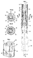
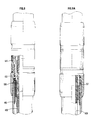
- FIG. 1 represents a block diagram of the device which will allow a better understanding of the operation of the means for controlling the angle of misalignment of the two elements with respect to each other.
- the lower element 1 is assembled with the upper element 2 by an articulated means of the ball-joint type 3.
- the lower element 1 is extended beyond the articulation 3 by a lever arm 7.
- the latter is present on the Figure 1, a portion of length in the form of a regular prism whose cross section has four parallel sides two by two and whose pairs of faces are perpendicular to each other.
- the guidance and control means are located at this portion of the lever arm.
- the guide means 4 comprise a slot 11 of elongated shape dimensioned to guide the lever arm 7 in the plane of movement.
- the guide means 4 are integral with the upper element 2.
- the means for controlling the angle of misalignment of the two elements 1 and 2 comprise a part substantially in the form of a ring 5.
- the external surface of this ring 5 is concentric in the body of the upper element 2 and free to rotate around of axis 12.
- the ring 5 has an interior recess of circular shape, the center of which is off-center with respect to the axis 12 which represents the axis of rotation of the ring 5.
- This eccentric recess will give the ring the name of eccentric 5. This term will be used in the following description.
- a control shaft 9 is integral in rotation with the eccentric ring 5.
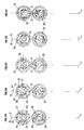
- the part 6 comprises an opening 10 of elongated shape dimensioned to cooperate with the faces 14 and 15 of the lever arm. This light is preferably centered on the axis of the part 6.
- the guide means are placed elsewhere than at the level of the lever arm 7. They may in particular be substantially at the level of the ball joint 3 or even opposite the lever arm 7 with respect to the joint.
- the guide means maintain the angular displacement of the lower element in a single plane containing the axis 12 of the upper element.
- a guide means which further excludes the rotation of the lower element around its longitudinal axis 13. This is not limiting of the principle which is based in particular on the fact that the light guide faces of the part 6 must remain perpendicular to the plane of movement and parallel to the axis 13. This is particularly the case where it is desired to reduce the mechanical play.
- the faces 14 and 15 are fixed in rotation by the guide means and the cooperation of the faces 14 and 15 with the light 10 indexes the position of the part 6 in the desired direction.
- the faces 14 and 15 which are subject to remain in the plane perpendicular to the plane of movement of the lever arm are driven, by cooperation with the light 10 of the part 6, substantially in a translational movement on either side of the axis 12.
- the lower element, linked to said faces by the lever arm, is thereby displaced in an angular manner around the joint and in the plane of movement.
- the value of the misalignment angle (i) is the angle between axis 12 and axis 13.
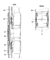
- control shaft 24 is connected by coupling means, with remote actuation equipment such as that taught by patent FR-2641320.
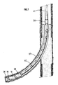
- bottom motor In both cases where the bottom motor is either screwed onto the upper element of the device, or screwed onto the lower element, it is preferable to use a type of bottom motor whose length is comparable with the length of the elements articulated 37.
- the articulated elements do not need to include a flexible torque transmission shaft, but simply allow the circulation of a pressurized fluid to the drilling tool.
Landscapes
- Engineering & Computer Science (AREA)
- Life Sciences & Earth Sciences (AREA)
- Geology (AREA)
- Mining & Mineral Resources (AREA)
- Physics & Mathematics (AREA)
- Environmental & Geological Engineering (AREA)
- Fluid Mechanics (AREA)
- General Life Sciences & Earth Sciences (AREA)
- Geochemistry & Mineralogy (AREA)
- Mechanical Engineering (AREA)
- Earth Drilling (AREA)
Claims (13)
- Vorrichtung, die es ermöglicht, zwei durch eine gelenkige Verbindung (3, 17) verbundenen Elementen (1, 2; 16, 18) einen Abweichungswinkel bezüglich einander in einer als Versetzungsebene bezeichneten Ebene einnehmen zu lassen, wobei eines der Elemente (1, 16), das als unteres bezeichnet ist, über die Gelenkverbindung (3, 17) in Form eines Hebelarms (7, 19) sich verlängert, das im zweiten hohlen als oberes bezeichneten Element (2, 18) angeordnet ist, dadurch gekennzeichnet, daß die Gelenkverbindung (3, 17) vom Typ Kugelgelenk ist, daß diese Vorrichtung Führungsmittel (4, 28 und 29) umfaßt, die die Verschiebung der beiden Elemente in dieser Versetzungsebene aufrecht erhalten, wobei diese Mittel in dieses obere Element (2, 18) eingebaut sind, daß diese Vorrichtung ebenfalls im oberen Element Mittel zum Regeln dieses Abweichungswinkels umfaßt und daß diese Regelmittel ein Element im wesentlichen von Ringform umfassen, das ein exzentrisches Loch (30) aufweist, dessen Winkelposition bezüglich der Achse (12) dieses zweiten Elements (2, 18) diesen Winkel bestimmt.
- Vorrichtung nach Anspruch 1, dadurch gekennzeichnet, daß dieser Hebelarm (7, 19) in diesem Loch (30) positioniert ist, wobei dieses Loch einen geraden Querschnitt kreisförmiger Gestalt aufweist, dessen Mitte exzentrisch bezüglich der Achse (12) des oberen Elements (2, 18) ist, daß in Höhe dieses Ringes (5, 25) dieser Hebelarm zwei Flächen (14, 15; 33 und 34) umfaßt, die symmetrisch bezüglich seiner Längsachse (13) und senkrecht zu der Versetzungsebene der beiden Elemente sind und daß diese Ausnehmung (30) ein Organ (6, 26 und 27) umfaßt, das mit Drehung durch diese Ausnehmung geführt ist und selbst über einen gegebenenfalls länglichen Schlitz (10) verfügt, der mit diesen Flächen (14, 15) des Hebelarms (7, 19) zusammenwirkt.
- Vorrichtung nach einem der Ansprüche 1 oder 2, dadurch gekennzeichnet, daß das untere Element (1, 16) hohl ist und am oberen Ende dieses Hebelarms (7, 19) eine nachgiebige und dichte Verbindung (21) aufweist, die mit dem Ende eines Kanals (22) zusammenwirkt, der die Zirkulation eines Fluides durch das untere Element ermöglicht.
- Vorrichtung nach einem der vorhergehenden Ansprüche, dadurch gekennzeichnet, daß das untere Element sich um seine Achse drehen kann, daß dieser Hebelarm mit wenigstens einer ko-axialen Büchse (20) zusammenwirkt und daß diese Büchse (22) eine Winkelposition hat, die fest bezüglich dieser Versetzungsebene ist.
- Vorrichtung nach Anspruch 4, dadurch gekennzeichnet, daß dieser mit dem oberen Ende des unteren Elements zusammenwirkende Kanal (22) eine hohle Welle zur Übertragung des Drehmoments auf dieses untere Element ist.
- Vorrichtung nach einem der Ansprüche 4 oder 5, dadurch gekennzeichnet, daß diese Führungs- und Regelmittel Systeme mit Schlitzen und Flächen (31, 32; 33, 34) umfassen und daß wenigstens gewisse dieser Flächen durch diese Büchse (20) getragen sind.
- Vorrichtung nach einem der Ansprüche 2 bis 6, dadurch gekennzeichnet, daß das in Drehung durch diese Ausnehmung (30) geführte Organ zwei identische Sektoren (26, 27) umfaßt, welche die beiden durch jede Fläche (33, 34) begrenzten Räume und die Ausnehmung (30) innerhalb des Ringes (25) ausfüllen, daß diese Ausnehmung (30) die Form eines symmetrischen Kugelabschnittes hat und daß diese Abschnitte (26, 27) Sektorabschnitte dieser Kugel sind.
- Vorrichtung nach einem der vorhergehenden Ansprüche, dadurch gekennzeichnet, daß das obere Element eine zu ihr konzentrische Betätigungswelle (24) aufweist und daß diese Welle drehfest mit dem Ring (25) ist.
- Vorrichtung nach einem der vorhergehenden Ansprüche, dadurch gekennzeichnet, daß sie Fernsteuermittel der Regelmittel für den Abweichungsausrichtwinkel der beiden Elemente umfaßt.
- Anwendung der Vorrichtung nach einem der vorhergehenden Ansprüche auf ein in eine Bohrausrüstung integriertes Aggregat.
- Anwendung der Vorrichtung nach Anspruch 10, dadurch gekennzeichnet, daß die Vorrichtung mit einem auf das untere Element (16) geschraubten Bohrwerkzeug (36) zusammenwirkt, mit einem Bodenmotor (38), einer Anordnung aus Gelenkelementen (37), Schwerstangen (39) und Bohrstangen (41).
- Anwendung der Vorrichtung nach einem der Ansprüche 10 oder 11, dadurch gekennzeichnet, daß die Bohrgarnitur von unten nach oben umfaßt: Ein Bohrwerkzeug (36), diese Vorrichtung, einen Bodenmotor (38), Gelenkelemente (37), Schwerstangen (39), Bohrstangen (41) und daß der Bodenmotor und die Gelenkelemente invertierbar sind.
- Anwendung der Vorrichtung nach Anspruch 10, dadurch gekennzeichnet, daß die Bohrgarnitur einen Bodenmotor (38) aufweist, der auf das untere Element (16) dieser Vorrichtung geschraubt ist und daß ein Bohrwerkzeug (36) auf den Rotor dieses Motors (38) geschraubt ist.
Applications Claiming Priority (3)
| Application Number | Priority Date | Filing Date | Title |
|---|---|---|---|
| FR9016442A FR2671130B1 (fr) | 1990-12-28 | 1990-12-28 | Dispositif comportant deux elements articules dans un plan, applique a un equipement de forage. |
| FR9016442 | 1990-12-28 | ||
| PCT/FR1991/000977 WO1992012324A1 (fr) | 1990-12-28 | 1991-12-06 | Dispositif comportant deux elements articules dans un plan, applique a un equipement de forage |
Publications (2)
| Publication Number | Publication Date |
|---|---|
| EP0517874A1 EP0517874A1 (de) | 1992-12-16 |
| EP0517874B1 true EP0517874B1 (de) | 1995-03-22 |
Family
ID=9403808
Family Applications (1)
| Application Number | Title | Priority Date | Filing Date |
|---|---|---|---|
| EP92901738A Expired - Lifetime EP0517874B1 (de) | 1990-12-28 | 1991-12-06 | Vorrichtung mit zwei in einer ebene beweglichen gelenkelementen für eine bohreinrichtung |
Country Status (5)
| Country | Link |
|---|---|
| US (1) | US5305838A (de) |
| EP (1) | EP0517874B1 (de) |
| CA (1) | CA2076627A1 (de) |
| FR (1) | FR2671130B1 (de) |
| WO (1) | WO1992012324A1 (de) |
Families Citing this family (31)
| Publication number | Priority date | Publication date | Assignee | Title |
|---|---|---|---|---|
| US5411082A (en) * | 1994-01-26 | 1995-05-02 | Baker Hughes Incorporated | Scoophead running tool |
| US5617926A (en) * | 1994-08-05 | 1997-04-08 | Schlumberger Technology Corporation | Steerable drilling tool and system |
| US5484029A (en) * | 1994-08-05 | 1996-01-16 | Schlumberger Technology Corporation | Steerable drilling tool and system |
| US5542482A (en) * | 1994-11-01 | 1996-08-06 | Schlumberger Technology Corporation | Articulated directional drilling motor assembly |
| US5727641A (en) * | 1994-11-01 | 1998-03-17 | Schlumberger Technology Corporation | Articulated directional drilling motor assembly |
| DE19612902C2 (de) * | 1996-03-30 | 2000-05-11 | Tracto Technik | Verfahren zum Richtungsbohren und eine Vorrichtung zur Durchführung des Verfahrens |
| US5803187A (en) * | 1996-08-23 | 1998-09-08 | Javins; Brooks H. | Rotary-percussion drill apparatus and method |
| US6092610A (en) * | 1998-02-05 | 2000-07-25 | Schlumberger Technology Corporation | Actively controlled rotary steerable system and method for drilling wells |
| US6158529A (en) * | 1998-12-11 | 2000-12-12 | Schlumberger Technology Corporation | Rotary steerable well drilling system utilizing sliding sleeve |
| US6109372A (en) * | 1999-03-15 | 2000-08-29 | Schlumberger Technology Corporation | Rotary steerable well drilling system utilizing hydraulic servo-loop |
| US6216802B1 (en) | 1999-10-18 | 2001-04-17 | Donald M. Sawyer | Gravity oriented directional drilling apparatus and method |
| DE60011587T2 (de) | 1999-11-10 | 2005-06-30 | Schlumberger Holdings Ltd., Road Town | Steuerungsverfahren für steuerbares bohrsystem |
| US7136795B2 (en) | 1999-11-10 | 2006-11-14 | Schlumberger Technology Corporation | Control method for use with a steerable drilling system |
| US6364034B1 (en) * | 2000-02-08 | 2002-04-02 | William N Schoeffler | Directional drilling apparatus |
| US20030127252A1 (en) * | 2001-12-19 | 2003-07-10 | Geoff Downton | Motor Driven Hybrid Rotary Steerable System |
| US7513318B2 (en) * | 2002-02-19 | 2009-04-07 | Smith International, Inc. | Steerable underreamer/stabilizer assembly and method |
| WO2003096075A1 (en) | 2002-05-13 | 2003-11-20 | Camco International (Uk) Limited | Recalibration of downhole sensors |
| US7861802B2 (en) * | 2006-01-18 | 2011-01-04 | Smith International, Inc. | Flexible directional drilling apparatus and method |
| US7506703B2 (en) * | 2006-01-18 | 2009-03-24 | Smith International, Inc. | Drilling and hole enlargement device |
| FR2898935B1 (fr) * | 2006-03-27 | 2008-07-04 | Francois Guy Jacques Re Millet | Dispositif d'orientation d'outils de forage |
| US7810582B2 (en) * | 2007-11-19 | 2010-10-12 | Webb Charles T | Counterbalance enabled power generator for horizontal directional drilling systems |
| US9410390B2 (en) * | 2010-08-24 | 2016-08-09 | Stanislav Tolstihin | Device for drilling through a formation |
| US9068423B2 (en) | 2012-02-03 | 2015-06-30 | National Oilwell Varco, L.P. | Wellhead connector and method of using same |
| US9074450B2 (en) | 2012-02-03 | 2015-07-07 | National Oilwell Varco, L.P. | Blowout preventer and method of using same |
| CN104271870B (zh) * | 2012-04-04 | 2017-09-22 | 国民油井华高公司 | 错位耐受的井场连接器组件、系统和方法 |
| US9169710B2 (en) | 2012-04-05 | 2015-10-27 | National Oilwell Varco, L.P. | Wellsite connector with piston driven collets and method of using same |
| CN103061674A (zh) * | 2012-11-29 | 2013-04-24 | 中国石油集团长城钻探工程有限公司 | 井下油层钻孔器 |
| US9366087B2 (en) * | 2013-01-29 | 2016-06-14 | Schlumberger Technology Corporation | High dogleg steerable tool |
| WO2015200390A1 (en) * | 2014-06-24 | 2015-12-30 | Pine Tree Gas, Llc | Systems and methods for drilling wellbores having a short radius of curvature |
| WO2017000053A1 (en) | 2015-07-02 | 2017-01-05 | Halliburton Energy Services, Inc. | Drilling apparatus with a fixed internally tilted driveshaft |
| CN111287659B (zh) * | 2020-03-30 | 2021-09-07 | 西安石油大学 | 一种基于全旋转指向式导向钻井工具的造斜率调节方法 |
Family Cites Families (11)
| Publication number | Priority date | Publication date | Assignee | Title |
|---|---|---|---|---|
| US3190374A (en) * | 1960-12-22 | 1965-06-22 | Neyrpic Ets | Soil drilling apparatus having means to change the direction of the drill |
| US3586116A (en) * | 1969-04-01 | 1971-06-22 | Turboservice Sa | Directional drilling equipment |
| US3627356A (en) * | 1969-11-19 | 1971-12-14 | Edwin A Anderson | Directional drilling apparatus with retrievable limiting device |
| US3667556A (en) * | 1970-01-05 | 1972-06-06 | John Keller Henderson | Directional drilling apparatus |
| US3853186A (en) * | 1973-03-12 | 1974-12-10 | Continental Oil Co | Drilling assembly deflection apparatus |
| US4396073A (en) * | 1981-09-18 | 1983-08-02 | Electric Power Research Institute, Inc. | Underground boring apparatus with controlled steering capabilities |
| GB8531382D0 (en) * | 1985-12-20 | 1986-02-05 | Kayes A G | Soil displacement hammer |
| US4834196A (en) * | 1987-06-22 | 1989-05-30 | Falgout Sr Thomas E | Well drilling tool |
| DE3735018C2 (de) * | 1987-07-25 | 1995-02-16 | Schmidt Paul | Rammbohrgerät |
| US4928776A (en) * | 1988-10-31 | 1990-05-29 | Falgout Sr Thomas E | Deviation control tool |
| US4895214A (en) * | 1988-11-18 | 1990-01-23 | Schoeffler William N | Directional drilling tool |
-
1990
- 1990-12-28 FR FR9016442A patent/FR2671130B1/fr not_active Expired - Fee Related
-
1991
- 1991-12-06 US US07/920,445 patent/US5305838A/en not_active Expired - Fee Related
- 1991-12-06 WO PCT/FR1991/000977 patent/WO1992012324A1/fr not_active Ceased
- 1991-12-06 EP EP92901738A patent/EP0517874B1/de not_active Expired - Lifetime
- 1991-12-06 CA CA002076627A patent/CA2076627A1/fr not_active Abandoned
Also Published As
| Publication number | Publication date |
|---|---|
| WO1992012324A1 (fr) | 1992-07-23 |
| US5305838A (en) | 1994-04-26 |
| FR2671130B1 (fr) | 1993-04-23 |
| EP0517874A1 (de) | 1992-12-16 |
| FR2671130A1 (fr) | 1992-07-03 |
| CA2076627A1 (fr) | 1992-06-29 |
Similar Documents
| Publication | Publication Date | Title |
|---|---|---|
| EP0517874B1 (de) | Vorrichtung mit zwei in einer ebene beweglichen gelenkelementen für eine bohreinrichtung | |
| EP2004946B1 (de) | Vorrichtung zum lenken von bohrwerkzeugen | |
| CA2006939C (fr) | Garniture de forage a trajectoire controlee comportant un stabilisateur a geometrie variable et utilisation de cette garniture | |
| CA1128925A (fr) | Raccord coude a angle variable pour forages diriges | |
| CA2006920C (fr) | Equipement pour garniture de forage comportant un element a actionner, un moteur et des moyens de commande | |
| WO1997035085A1 (fr) | Dispositif de protection et de guidage d'un composant allonge associe, au niveau de l'articulation, a deux elements rigides articules l'un a l'autre, et ses applications industrielles | |
| CA2006927C (fr) | Garniture de forage a trajectoire controlee comportant un element coude a angle variable et utilisation de cette garniture | |
| FR2577005A1 (fr) | Manchon-raccord a la cardan pour des systemes de canalisations | |
| CA1294604C (fr) | Dispositif de reglage a distance de l'orientation relative de deux troncons d'une colonne | |
| WO2001092761A1 (fr) | Transmission a vis, ecrou et cable attache a la vis | |
| EP0013845A1 (de) | Kugelgelenk für Gelenkarm | |
| FR2544422A1 (fr) | Dispositif d'accouplement a petit debattement pour arbres oscillants | |
| WO2011064467A1 (fr) | Composants de garniture de forage et train de composants | |
| EP0884505A1 (de) | Vorrichtung mit einem drehbaren Hebel zur Bewegungsüberbringung und Ventil mit einer solchen Vorrichtung | |
| FR2722238A1 (fr) | Ensemble de mesure comportant des moyens d'orientation d'une partie des elements de mesure | |
| CA2382596C (en) | Directional well drilling | |
| WO2004113763A1 (fr) | Verin a vis et ecrou | |
| EP0275737A1 (de) | Löt- bzw. Schweissgasbrenner mit gegliedertem und ausziehbarem Körper | |
| EP0042330B1 (de) | Homokinetische Kupplung | |
| EP0843050B1 (de) | Eine Bohrvorrichtung enthaltende Bohranlage | |
| BE865955A (fr) | Perfectionnements aux installations de forage | |
| CA2055481C (fr) | Dispositif de transmission etanche d'un mouvement de rotation, a soufflet metallique | |
| FR2827926A1 (fr) | Joint universel a croisillon double, centre | |
| CA1254757A (fr) | Dispositif d'accouplement a denture pour arbres oscillants | |
| FR2548298A1 (fr) | Joint homocinetique |
Legal Events
| Date | Code | Title | Description |
|---|---|---|---|
| PUAI | Public reference made under article 153(3) epc to a published international application that has entered the european phase |
Free format text: ORIGINAL CODE: 0009012 |
|
| 17P | Request for examination filed |
Effective date: 19920814 |
|
| AK | Designated contracting states |
Kind code of ref document: A1 Designated state(s): GB IT NL |
|
| 17Q | First examination report despatched |
Effective date: 19930903 |
|
| GRAA | (expected) grant |
Free format text: ORIGINAL CODE: 0009210 |
|
| AK | Designated contracting states |
Kind code of ref document: B1 Designated state(s): GB IT NL |
|
| ITF | It: translation for a ep patent filed | ||
| GBT | Gb: translation of ep patent filed (gb section 77(6)(a)/1977) |
Effective date: 19950321 |
|
| PLBE | No opposition filed within time limit |
Free format text: ORIGINAL CODE: 0009261 |
|
| STAA | Information on the status of an ep patent application or granted ep patent |
Free format text: STATUS: NO OPPOSITION FILED WITHIN TIME LIMIT |
|
| 26N | No opposition filed | ||
| PG25 | Lapsed in a contracting state [announced via postgrant information from national office to epo] |
Ref country code: NL Effective date: 19960701 |
|
| NLV4 | Nl: lapsed or anulled due to non-payment of the annual fee |
Effective date: 19960701 |
|
| PGFP | Annual fee paid to national office [announced via postgrant information from national office to epo] |
Ref country code: GB Payment date: 19961118 Year of fee payment: 6 |
|
| PG25 | Lapsed in a contracting state [announced via postgrant information from national office to epo] |
Ref country code: GB Free format text: LAPSE BECAUSE OF NON-PAYMENT OF DUE FEES Effective date: 19971206 |
|
| GBPC | Gb: european patent ceased through non-payment of renewal fee |
Effective date: 19971206 |
|
| PG25 | Lapsed in a contracting state [announced via postgrant information from national office to epo] |
Ref country code: IT Free format text: LAPSE BECAUSE OF NON-PAYMENT OF DUE FEES;WARNING: LAPSES OF ITALIAN PATENTS WITH EFFECTIVE DATE BEFORE 2007 MAY HAVE OCCURRED AT ANY TIME BEFORE 2007. THE CORRECT EFFECTIVE DATE MAY BE DIFFERENT FROM THE ONE RECORDED. Effective date: 20051206 |