EP0518082A2 - Appareil pour le bricolage des décorations de paille - Google Patents
Appareil pour le bricolage des décorations de paille Download PDFInfo
- Publication number
- EP0518082A2 EP0518082A2 EP92108386A EP92108386A EP0518082A2 EP 0518082 A2 EP0518082 A2 EP 0518082A2 EP 92108386 A EP92108386 A EP 92108386A EP 92108386 A EP92108386 A EP 92108386A EP 0518082 A2 EP0518082 A2 EP 0518082A2
- Authority
- EP
- European Patent Office
- Prior art keywords
- clamping ring
- ring
- interruption
- rods
- laying aid
- Prior art date
- Legal status (The legal status is an assumption and is not a legal conclusion. Google has not performed a legal analysis and makes no representation as to the accuracy of the status listed.)
- Withdrawn
Links
- 239000010902 straw Substances 0.000 title claims abstract description 50
- 238000005034 decoration Methods 0.000 title 1
- 238000004904 shortening Methods 0.000 claims abstract description 7
- 230000007480 spreading Effects 0.000 claims description 6
- 238000003892 spreading Methods 0.000 claims description 6
- 210000002105 tongue Anatomy 0.000 description 9
- JXYWFNAQESKDNC-BTJKTKAUSA-N (z)-4-hydroxy-4-oxobut-2-enoate;2-[(4-methoxyphenyl)methyl-pyridin-2-ylamino]ethyl-dimethylazanium Chemical compound OC(=O)\C=C/C(O)=O.C1=CC(OC)=CC=C1CN(CCN(C)C)C1=CC=CC=N1 JXYWFNAQESKDNC-BTJKTKAUSA-N 0.000 description 7
- 210000003811 finger Anatomy 0.000 description 5
- 230000004048 modification Effects 0.000 description 5
- 238000012986 modification Methods 0.000 description 5
- MOVRNJGDXREIBM-UHFFFAOYSA-N aid-1 Chemical compound O=C1NC(=O)C(C)=CN1C1OC(COP(O)(=O)OC2C(OC(C2)N2C3=C(C(NC(N)=N3)=O)N=C2)COP(O)(=O)OC2C(OC(C2)N2C3=C(C(NC(N)=N3)=O)N=C2)COP(O)(=O)OC2C(OC(C2)N2C3=C(C(NC(N)=N3)=O)N=C2)COP(O)(=O)OC2C(OC(C2)N2C(NC(=O)C(C)=C2)=O)COP(O)(=O)OC2C(OC(C2)N2C3=C(C(NC(N)=N3)=O)N=C2)COP(O)(=O)OC2C(OC(C2)N2C3=C(C(NC(N)=N3)=O)N=C2)COP(O)(=O)OC2C(OC(C2)N2C3=C(C(NC(N)=N3)=O)N=C2)COP(O)(=O)OC2C(OC(C2)N2C(NC(=O)C(C)=C2)=O)COP(O)(=O)OC2C(OC(C2)N2C3=C(C(NC(N)=N3)=O)N=C2)COP(O)(=O)OC2C(OC(C2)N2C3=C(C(NC(N)=N3)=O)N=C2)COP(O)(=O)OC2C(OC(C2)N2C3=C(C(NC(N)=N3)=O)N=C2)COP(O)(=O)OC2C(OC(C2)N2C(NC(=O)C(C)=C2)=O)COP(O)(=O)OC2C(OC(C2)N2C3=C(C(NC(N)=N3)=O)N=C2)COP(O)(=O)OC2C(OC(C2)N2C3=C(C(NC(N)=N3)=O)N=C2)COP(O)(=O)OC2C(OC(C2)N2C3=C(C(NC(N)=N3)=O)N=C2)CO)C(O)C1 MOVRNJGDXREIBM-UHFFFAOYSA-N 0.000 description 2
- 230000000694 effects Effects 0.000 description 2
- 238000004519 manufacturing process Methods 0.000 description 2
- 206010016352 Feeling of relaxation Diseases 0.000 description 1
- 230000009471 action Effects 0.000 description 1
- 230000008901 benefit Effects 0.000 description 1
- 230000015572 biosynthetic process Effects 0.000 description 1
- 230000008859 change Effects 0.000 description 1
- 230000001419 dependent effect Effects 0.000 description 1
- 210000004905 finger nail Anatomy 0.000 description 1
- 210000005224 forefinger Anatomy 0.000 description 1
- 230000005484 gravity Effects 0.000 description 1
- 239000002184 metal Substances 0.000 description 1
- 238000012856 packing Methods 0.000 description 1
- 239000007787 solid Substances 0.000 description 1
- 238000005728 strengthening Methods 0.000 description 1
- 210000003813 thumb Anatomy 0.000 description 1
- 239000002023 wood Substances 0.000 description 1
Images




Classifications
-
- B—PERFORMING OPERATIONS; TRANSPORTING
- B44—DECORATIVE ARTS
- B44C—PRODUCING DECORATIVE EFFECTS; MOSAICS; TARSIA WORK; PAPERHANGING
- B44C3/00—Processes, not specifically provided for elsewhere, for producing ornamental structures
-
- B—PERFORMING OPERATIONS; TRANSPORTING
- B44—DECORATIVE ARTS
- B44C—PRODUCING DECORATIVE EFFECTS; MOSAICS; TARSIA WORK; PAPERHANGING
- B44C5/00—Processes for producing special ornamental bodies
- B44C5/06—Natural ornaments; Imitations thereof
-
- D—TEXTILES; PAPER
- D04—BRAIDING; LACE-MAKING; KNITTING; TRIMMINGS; NON-WOVEN FABRICS
- D04C—BRAIDING OR MANUFACTURE OF LACE, INCLUDING BOBBIN-NET OR CARBONISED LACE; BRAIDING MACHINES; BRAID; LACE
- D04C7/00—Tools or apparatus for braiding or lacing by hand
Definitions
- the invention relates to a laying aid for tinkering straw stars with a laying part made of a central disc, in the top of which a wreath of upright rods is anchored, and with a loose clamping ring which fits tightly into the rod wreath under elastic tension.
- straw strips formed by longitudinally splitting straws are placed crossed between the rods on the upper side of the central disk so that they form the pattern of a star and their ends protrude beyond the central disk.
- the straw strips intersect at these protruding ends and they are connected to one another at the intersections, as a result of which the straw star which has been laid gains its hold so that it can be removed from the laying aid after these connections have been made.
- the formation and binding of the straw star is made easier, particularly in the case of stacked layers of straw, by the clamping ring, which is placed from above onto the layer of straw that has already been reached and which compresses and holds it together for binding or for provisional holding during an interruption of laying.
- the clamping ring is a closed rubber ring.
- the object of the invention is to design the clamping ring so that it is used securely by tension and is also able to withstand the lifting forces emanating from the position of the straw strips and, on the other hand, is easily removable, also taking into account is that such laying aids from small children with correspondingly weak forces can be used in the fingers.
- the clamping ring has an opening forming an opening in its circumference, that the two ends of the clamping ring delimiting the opening are movable towards each other against a restoring force inherent in the clamping ring while shortening the interruption, and in that the clamping ring also moves with a shortened interruption Game fits into the pole ring, but not when the break is spread.
- Such a clamping ring can be designed so that it sits relieved with considerable tension and thus with a solid clamping effect in the rod collar. However, it can be easily removed because it is only necessary to shorten the interruption accordingly.
- the handling associated therewith can be favored in that both ends of the clamping ring each have a handle which is turned away when the clamping ring of the central disk is inserted and which are advantageously arranged along the legs of the U-shaped bracket.
- Such a handle can be a projection that is easy to grasp with the fingers from above. But there can also be recesses that can be gripped with fingers or pliers. An embodiment of the handles as projections is preferred because they are more convenient to use.
- the projections are expediently designed such that they are aligned with the underside of the clamping ring facing the central disk when the clamping ring is inserted, and so continue the support on the straw star into the interruption.
- the spread of the interruption can then be easily limited so that it is just enough to clamp the clamping ring used. Then a small shortening of the interruption is sufficient to insert the loose clamping ring in the pole ring.
- the tension with which it is to be fitted is no longer dependent on the stroke with which the interruption for inserting the clamping ring is shortened due to the action of the stop.
- the cross section of the clamping ring is rectangular, with two sides of the rectangle parallel to the plane of the ring.
- the rods are perpendicular to the surface of the central disc.
- the clamping ring with a rectangular cross-section then fits positively into the cross-sectional shape of the open space between the surface of the central disk and the inside of the rod ring. If an open space with a different cross-sectional shape is defined between the rods and the central disk, then you can either use a clamping ring with a rectangular cross-section, but you can also use a clamping ring whose cross-section is form-fittingly adapted to the cross-sectional shape of this open space. Finally, it is also possible to use a clamping ring with a round or oval cross section. The round and rectangular cross-sectional shape is preferred because it is easier to manufacture and more general use.
- the form-fitting, non-round and non-rectangular cross-sectional shape is preferred if it matters, if possible to achieve a positive fit, on the one hand, to compress the straw star packing tightly, and on the other hand, to find sufficient frictional grip on the rods.
- the main pattern of the star is formed within the pole wreath.
- the finished star only protrudes with the tapering ends of the straw strips and the connections at the crossing points are close to the circumference of the laying aid.
- the size of a straw star to be crafted is limited by the diameter of the laying aid.
- the object of a development of the invention is to reduce the additional effort required in this connection in the production of the laying aid.
- This object is achieved in that a loose extension ring is provided which fits coaxially tight on the circumference of the central disk, which can be extended radially outwards, and that a ring of rods is provided, the rods of which are anchored or anchored on the top of the extension ring are.
- the rods of the central disc may get in the way when placing a straw star with an extension ring attached.
- One solution is that when the extension ring is attached, the smooth underside of the central disk is flush with the top of the extension ring by the extension ring with its top facing upward fitting on the central disk facing downward, that is to say turned. Then the poles of the central disc are on the side of the laying aid that faces away from the straw star to be laid and are out of the way.
- the second solution consists in that the top of the extension ring is placed flush with the top of the central disk on the central disk, in that the top of the extension ring fits with the top of the central disk, which also faces upward, i.e. does not turn, and that the rods the central disc are removable and removed with the extension ring attached.
- This solution is somewhat more complex because the rods must be designed to be removable, but offers the advantage that the rods that are not required or are in the way do not protrude from the underside of the laying aid and may interfere with handling there.
- a second, loose extension ring is sufficient, which, like the first extension ring on the central disc, fits on the first extension ring and so on with any other extension rings provided.
- the laying aid can be designed as in the two solutions described above in such a way that the rods of the central disk and possibly the rods of one or more extension rings, with the exception of the outermost extension ring attached, from which the outermost extension ring defined surface can be removed by removing or by turning the central disc and if necessary the relevant inner extension rings.
- each star made is a plane star.
- the object of a further development of the invention is also to offer help for tinkering curved straw stars.
- the straw strips are straight at first. They are then appropriately pre-curved by pulling them between a hard edge, for example the thumb fingernail, and a soft counterpart, for example the forefinger tip. If the original inside of the straw glides over the edge, the straw strip bulges permanently with the original outside facing outwards.
- the straw strips are placed with the outside of the straw facing upwards on the curved top of the central disk, so that they form a curved star. This is fixed in its curvature by the clamping ring and then the ends are connected to each other, as with a flat star.
- the curved upper side can be integrally formed on the central disk, but it can also be formed by a loose insert that fits positively on the central disk formed with a flat upper side and between the rod ring.
- the insert is usefully fixable with a light press fit compared to the pole ring.
- the angular orientation of the insert part can be done simply by providing one or more tongues on the insert part which are distributed over the circumference and which project radially outwards and are dimensioned so narrow in the circumferential direction that they are between two adjacent rods fit.
- the desired clamping fit can be brought about by the tongues by fitting them between two adjacent rods.
- the curvature of the top can be round without kinks, it can but also be formed or formed by buckling edges.
- the rods can extend parallel to the axis of the central disc, but they can also be inclined obliquely outwards, preferably according to the curvature, so that they are perpendicular to the outer edge of the curvature.
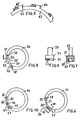
- 1 designates a laying aid, which consists of a circular plastic disc 2, on the circumference of which are uniformly distributed in a centrally symmetrical arrangement, rods 3 to 9 of equal size, which extend perpendicular to the plane defined by the central disc 14.
- a clamping ring 10 is inserted into this ring of rods.
- This clamping ring 10 has an opening 11 forming an opening on its circumference.
- the clamping ring 10 is made of elastic plastic, so that the two ring ends 12, 13 forming the interruption 11 can be moved towards one another against the restoring force inherent in the clamping ring while shortening the interruption. In the relaxed state, the clamping ring does not fit into the collar. It only fits in with a short interruption and then, when released, sits tightly inside the pole ring.
- the interruption 11 is bridged by a U-shaped bracket 29 designed as a resilience, which is formed on the two clamping ring ends 12, 13.
- a U-shaped bracket 29 designed as a resilience, which is formed on the two clamping ring ends 12, 13.
- an upward-facing handle 15, 16 is provided, which is arranged along the legs 48, 49 of the bracket 29. Due to the restoring force inherent in the bracket 29, when the clamping ring is compressed, the restoring force of the clamping ring directed towards spreading becomes 10 reinforced.
- the bracket 29 is molded onto the clamping ring 10. Bracket 29 and clamping ring 10 preferably consist of a one-piece plastic part.
- the bracket 29 can also stop if the restoring force of the clamping ring 10 is sufficiently large. Then the handles corresponding to the handles 15, 16 are attached to the two end pieces of the clamping ring, as indicated by dashed lines in FIG. 1 under positions 67 and 68. If the restoring force of the clamping ring 10 is sufficiently large, the section 69 of the bracket 29 between the two handles 15, 16 can also cease to exist.
- the cross-section of the clamping ring 10 is adapted to the cross-sectional shape of the open space between the surface 17 of the central disk 14 and the inside of the rod collar 3, 4 and has the shape of a rectangle according to Figures 1 to 3.
- the cross section of the clamping ring 39 which corresponds to the clamping ring 10 from FIGS. 1 to 3, has the shape of a trapezoid with the narrow side inwards, so that a wedge-shaped gap 85 with its tip directed outwards between the clamping ring 39 and the central disc 14 remains free. This favors the frictional force and thus the fit of the clamping ring.
- the tension of the clamping ring 10 is selected so that it can be conveniently inserted into the rod ring on the one hand, but is braced there with sufficient strength on the other hand.
- the clamping ring 10 has a rectangular cross section.
- the clamping ring 62 shown in Figure 5 has on its circumference arranged, radially outwardly projecting tongues 63, 64 which are dimensioned so narrow in the circumferential direction that they fit between two adjacent rods, for example the rods 65, 66 of the associated laying aid .
- the tongues 63, 64 are preferably dimensioned so wide that they fit in a clamping manner between two adjacent rods and thereby fix or additionally fix the clamping ring in its functional position.
- a projection 23 is provided on one clamping ring end 22, which protrudes into the interruption 24 and bridges it completely and has a place in a recess 25 at the opposite clamping ring end 26.
- the recess 25 is long enough so that the clamping ring 21 can be compressed sufficiently.
- the two handles corresponding to handles 15 and 16 are designated 27 and 28.
- projections 33, 34 are provided on both clamping ring ends 31 and 32, which project overlapping one another into the spread interruption 35.
- the projections 33 and 34 each do not extend over the entire length of the spread interruption 35 and find, even if the clamping ring is compressed sufficiently is still 35 place in the break to fit in the pole ring.
- the two handles corresponding to the handles 15 and 16 are 37 and 38.
- the projections are aligned with the underside of the clamping ring, that is to say with the side with which it fits into the bar collar on the straw strip, so that the projections prevent sections of straw strip from continuing into the interruption to dodge at the top.
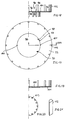
- the surface 17 of the central disk on which the straw star is formed is a plane. In the exemplary embodiments according to FIGS. 11 to 16, this surface 50 is curved upwards.
- This curved surface 50 is achieved by an appropriately shaped insert 51 which is inserted into a laying aid 52.
- This laying aid 52 is designed as described in the text relating to FIG. 1, that is to say it consists of a flat, circular central disk 53 and upwardly projecting rods 54 to 57, which form a ring evenly distributed over the circumference.
- the associated clamping ring 58 which is designed as a loose part and drawn, has an approximately trapezoidal cross section, so that it conforms to the annular space formed by the rods on the one hand and by the surface 50 on the other.
- the insert 51 is provided with a plurality of radial tongues 59, 60 distributed over the circumference, which are each dimensioned so narrow in the circumferential direction that they fit between two adjacent rods, the tongue 59, for example between the rods 54, 55, and thereby fix the insert 51 sufficiently in the inserted state.
- the radial tongues 59, 60 ... can also be omitted and this insert with a circular circumference can be designed to fit in a form-fitting manner in the rod collar and hold there sufficiently by gravity.
- a domed star is placed from straw strips, as indicated by the dash-dotted line 61.
- the straw strips are preferably pre-curved for this purpose by pulling them between two pressed fingers, namely the original inside along the transverse thumbnail and the original outside along the index finger tip.
- the embodiment of Figure 11 can also be used to lay out flat straw stars.
- the insert 51 is let out.
- the trapezoidal cross section of the clamping ring 58 is not optimal for this case, but it is sufficient.
- a clamping ring with a rectangular cross-section can also be used, such as the clamping ring 72 from FIG. 13.
- the exemplary embodiment according to FIG. 13 differs from the exemplary embodiment according to FIG. 11 only in that the curved surface 70 corresponding to the curved surface 50 is formed by the central disk 71, which is designed to be curved accordingly. A special insert is therefore not required.
- the clamping ring 72 is formed with a rectangular cross section for the sake of simplicity.
- the curved surface 74 is formed by the central disk 75.
- the rods for example rod 73, are not perpendicular to the plane defined by the central disk, but are inclined slightly outward, to the extent that they are perpendicular to the corresponding curvature corresponding to tangent 76.
- the clamping ring 77 is positively adapted to the curved surface 74 and the rods in terms of its cross section.
- the clamping ring is not shown in FIGS. 15 and 16. Both embodiments are very similar to the embodiment according to FIG. 13, the only difference being that according to FIG. 13 the curved surface 70 is round, while the curved surface 78 has annular fold edges 79 and 80 and circular-conical sections between the fold edges.
- annular buckling edges 81, 82 are also provided in the curved surface 83.
- the section between these fold edges, for example section 84, is slightly curved.
- clamping rings are no longer shown, they can be designed accordingly as described in the text for FIGS. 1 to 10 and are adapted in size to the rod collar in operation.
- FIGS. 17 and 18 show a laying aid 90 which is designed in exactly the same way as the laying aid 1 from FIG. 1. It is only arranged with its rods 91 ... and its top 92 facing downwards and radially outwards by means of an attached extension ring 93 extended. This extension ring 93 faces upwards with its top 94 and this is flush with the smooth bottom 95 of the central disk 96 of the laying aid 90.
- the extension ring 93 is placed with its inner circumference 97 on the outer circumference 98 of the central disk 96 and is releasably secured again by means of molded catches 100, 101 distributed over the circumference.
- the extension ring 93 has uniformly distributed rods 102 of equal length on its circumference in a centrally symmetrical arrangement, which extend perpendicular to the surface 94.
- the laying aid formed by the central disk 96 and the extension ring 93 is also covered with straw strips to form a star, although longer straw strips can be used so that a larger star is formed.
- the rods 102 ... of the extension ring 93 serve as guides, while the rods 91 ... of the laying aid 90 have no function are. If you want to place a smaller straw star, then you remove the extension ring again, turn the laying aid 90 around and use it as described in the text for Figures 1 to 3.
- a small clamping ring is available for the rod ring of rods 91 ..., a larger clamping ring is available for the rod ring of rods 102 ...
- the rods 91... Of the laying aid 90 can also be pulled out. You pull them out when they are not needed so that they do not interfere with the bottom.
- the result is a large laying aid formed from a central disk 110, an extension ring 111 and the rods 112 ... associated with the extension ring, which can be reduced by removing the extension ring 111 and the rods, for example the rod 112, back in the holes 113 ... provided.
- the removable rods can be functionally shaped, for example like the rod 114 from FIGS. 22 and 23, which has a circular cross section 115 at its upper end and has a plug 116 at its lower end, which fits into a hole corresponding to the hole 113 the central disc fits.
- FIGS. 24 to 28 Modified embodiments result from FIGS. 24 to 28.
- the connectors with a trapezoidal cross section from FIGS. 26, 27 and 28 are noteworthy, for which, as shown in FIG. 20, trapezoidal holes 113.. are directed radially inwards and offer a particularly secure hold.
- the connector tapered can also continue be designed as the plug 117 of the rod 118.
- the cross-sectional shape from FIG. 30 belongs to FIG. 29 and modifications are shown in FIGS. 31 to 35.
- a laying aid can also be enlarged by more than one extension ring, for example by two extension rings, as shown in FIG. 36.
- 130 shows a laying aid corresponding to the laying aid 1 from FIG. 1, which is installed turned, namely with its top side facing down.
- a first extension ring 131 is attached to this laying aid 130, which likewise points downward with its associated rods, that is to say is turned over.
- Around this first extension ring 131 is a second extension ring 132, which points upwards with its rods 133 ... and its surface 134 and whose surface 134 forms a continuous work surface with the rear sides of the extension ring 131 and the laying aid 130, on which the straw strips are placed can be.
- the rods 135 ... of the laying aid 130 and the rods 136 ... of the extension ring 131 point downwards and have no function.
- the functionless rods of the laying aid 140 and the first extension ring 141 can be pulled out and, because they are not needed at the moment, pulled out, so that only the rods 142 ... of the second extension ring 143 that are required for function are present. Otherwise, the exemplary embodiment according to FIG. 37 is designed in exactly the same way as that according to FIG. 36.
- FIGS. 38 to 41 four modified embodiments are shown in sections, of which only parts of the clamping ring 150 to 153 and an associated rod 154 to 157 of the associated pole ring are shown.
- sliding brakes 158 to 165 are fitted on the outside of the clamping ring and on the inside of the rods, specifically according to FIG. 38, studs 158 on the rods and a downward barb barb 162 on the clamping ring, according to FIG. 39, studs 159 on the inside of the rods and a pointed one Edge 163 on the outside of the clamping ring, according to FIG.
- undulations 160 extending horizontally on the rods 156 and a round curvature 164 fitting therein, on the outside of the clamping ring and, according to FIG. 41, barbs 161 on the inside of the rods and an upwardly directed barb-like edge 165 outside of the clamping ring.
- the described parts of all exemplary embodiments namely the central disk, the extension rings with the molded or insertable rods and the clamping rings are preferably molded from plastic, but they can also be molded from metal or wood.
Landscapes
- Engineering & Computer Science (AREA)
- Textile Engineering (AREA)
- Table Equipment (AREA)
Applications Claiming Priority (6)
| Application Number | Priority Date | Filing Date | Title |
|---|---|---|---|
| DE9106850U | 1991-06-04 | ||
| DE9106851U | 1991-06-04 | ||
| DE9106852U | 1991-06-04 | ||
| DE9106850U DE9106850U1 (de) | 1991-06-04 | 1991-06-04 | Legehilfe zum Basteln von Strohsternen |
| DE9106852U DE9106852U1 (de) | 1991-06-04 | 1991-06-04 | Legehilfe für das Basteln von Strohsternen |
| DE9106851U DE9106851U1 (de) | 1991-06-04 | 1991-06-04 | Legehilfe für Bastler von Strohsternen |
Publications (2)
| Publication Number | Publication Date |
|---|---|
| EP0518082A2 true EP0518082A2 (fr) | 1992-12-16 |
| EP0518082A3 EP0518082A3 (en) | 1994-11-09 |
Family
ID=27208304
Family Applications (1)
| Application Number | Title | Priority Date | Filing Date |
|---|---|---|---|
| EP9292108386A Withdrawn EP0518082A3 (en) | 1991-06-04 | 1992-05-19 | Device for assembling hand-crafted straw decorations |
Country Status (2)
| Country | Link |
|---|---|
| EP (1) | EP0518082A3 (fr) |
| DE (1) | DE9209830U1 (fr) |
Cited By (2)
| Publication number | Priority date | Publication date | Assignee | Title |
|---|---|---|---|---|
| CN107214792A (zh) * | 2017-06-29 | 2017-09-29 | 湖南农业大学 | 一种全自动秸秆编织机 |
| CN113146779A (zh) * | 2021-04-09 | 2021-07-23 | 北川羌族自治县和谐旅游开发有限公司 | 南瓜草编方法及南瓜盆景的制备方法 |
Family Cites Families (3)
| Publication number | Priority date | Publication date | Assignee | Title |
|---|---|---|---|---|
| US2043770A (en) * | 1935-07-27 | 1936-06-09 | Frederick W Oltmanns | Ornament |
| GB8728633D0 (en) * | 1987-12-08 | 1988-01-13 | Congleton Eng Developments Ltd | Method & apparatus for making fabric adornment |
| GB2227977A (en) * | 1989-01-16 | 1990-08-15 | Congleton Eng Dev | Apparatus for controlling sequential movement |
-
1992
- 1992-05-19 EP EP9292108386A patent/EP0518082A3/de not_active Withdrawn
- 1992-07-22 DE DE9209830U patent/DE9209830U1/de not_active Expired - Lifetime
Cited By (3)
| Publication number | Priority date | Publication date | Assignee | Title |
|---|---|---|---|---|
| CN107214792A (zh) * | 2017-06-29 | 2017-09-29 | 湖南农业大学 | 一种全自动秸秆编织机 |
| CN107214792B (zh) * | 2017-06-29 | 2018-03-09 | 湖南农业大学 | 一种全自动秸秆编织机 |
| CN113146779A (zh) * | 2021-04-09 | 2021-07-23 | 北川羌族自治县和谐旅游开发有限公司 | 南瓜草编方法及南瓜盆景的制备方法 |
Also Published As
| Publication number | Publication date |
|---|---|
| EP0518082A3 (en) | 1994-11-09 |
| DE9209830U1 (de) | 1992-09-24 |
Similar Documents
| Publication | Publication Date | Title |
|---|---|---|
| DE2901061C2 (de) | Verschlußplombe | |
| DE2536424C3 (de) | Gegen unbefugtes öffnen gesicherter einteiliger Laschenverschluß | |
| DE2646024C3 (de) | Lösbares, schellenartiges sowie einstückiges Verbindungsmittel, insbesondere zum Schließen von Tüten oder zum Zusammenbinden eines Pflanzenstiels bzw. -Stammes mit einer Stütze oder auch zum Verbinden einer Vielzahl von elektrischen Kabeln | |
| DE908669C (de) | Unterleiste fuer Bretchenvorhaenge | |
| DE2128812B2 (de) | Aus federndem Material bestehender Klemmverbinder | |
| DE3516174C2 (de) | Befestigungsband | |
| DE1211032B (de) | Befestigungselement | |
| DE9209830U1 (de) | Legehilfe für das Basteln von Strohsternen | |
| DE4414577C2 (de) | Spule | |
| DE9106850U1 (de) | Legehilfe zum Basteln von Strohsternen | |
| DE9106852U1 (de) | Legehilfe für das Basteln von Strohsternen | |
| DE9106851U1 (de) | Legehilfe für Bastler von Strohsternen | |
| DE3001195A1 (de) | Schnappvorrichtung zur loesbaren verbindung von zwei teilen oder brettern | |
| DE3301592C2 (de) | Lockenwickel | |
| DE7038195U (de) | Neue rastenvorrichtung fuer klappmesser | |
| DE2710184C2 (de) | Sperrvorrichtung | |
| DE8911970U1 (de) | Dauerwellwickler | |
| DE948363C (de) | Spulenkoerper aus Kunststoff | |
| DE29514119U1 (de) | Schnur zum reversiblen Verschließen von Beutelöffnungen oder Zusammenhalten von Bündeln oder Strängen | |
| AT393106B (de) | Hefteinrichtung fuer blattstapel | |
| DE2154312C2 (de) | Mosaikstein für ein Mosaikspiel | |
| DE2460100A1 (de) | Loesbare drehsicherung fuer ein mit einem umfangsprofil versehenes teil | |
| DE2912702C2 (de) | Verbindungselement für Drahtgitter | |
| DE1536596A1 (de) | Reiter | |
| DE29818078U1 (de) | Tragevorrichtung für Wulsthalsflaschen |
Legal Events
| Date | Code | Title | Description |
|---|---|---|---|
| PUAI | Public reference made under article 153(3) epc to a published international application that has entered the european phase |
Free format text: ORIGINAL CODE: 0009012 |
|
| AK | Designated contracting states |
Kind code of ref document: A2 Designated state(s): AT CH DE FR GB IT LI |
|
| PUAL | Search report despatched |
Free format text: ORIGINAL CODE: 0009013 |
|
| AK | Designated contracting states |
Kind code of ref document: A3 Designated state(s): AT CH DE FR GB IT LI |
|
| STAA | Information on the status of an ep patent application or granted ep patent |
Free format text: STATUS: THE APPLICATION IS DEEMED TO BE WITHDRAWN |
|
| 18D | Application deemed to be withdrawn |
Effective date: 19941201 |