EP0518162A2 - Dispositif de commutation de securité pour véhicules - Google Patents
Dispositif de commutation de securité pour véhicules Download PDFInfo
- Publication number
- EP0518162A2 EP0518162A2 EP92109226A EP92109226A EP0518162A2 EP 0518162 A2 EP0518162 A2 EP 0518162A2 EP 92109226 A EP92109226 A EP 92109226A EP 92109226 A EP92109226 A EP 92109226A EP 0518162 A2 EP0518162 A2 EP 0518162A2
- Authority
- EP
- European Patent Office
- Prior art keywords
- switch
- seat
- flap
- arrangement according
- safety switch
- Prior art date
- Legal status (The legal status is an assumption and is not a legal conclusion. Google has not performed a legal analysis and makes no representation as to the accuracy of the status listed.)
- Withdrawn
Links
Images


Classifications
-
- B—PERFORMING OPERATIONS; TRANSPORTING
- B60—VEHICLES IN GENERAL
- B60K—ARRANGEMENT OR MOUNTING OF PROPULSION UNITS OR OF TRANSMISSIONS IN VEHICLES; ARRANGEMENT OR MOUNTING OF PLURAL DIVERSE PRIME-MOVERS IN VEHICLES; AUXILIARY DRIVES FOR VEHICLES; INSTRUMENTATION OR DASHBOARDS FOR VEHICLES; ARRANGEMENTS IN CONNECTION WITH COOLING, AIR INTAKE, GAS EXHAUST OR FUEL SUPPLY OF PROPULSION UNITS IN VEHICLES
- B60K28/00—Safety devices for propulsion-unit control, specially adapted for, or arranged in, vehicles, e.g. preventing fuel supply or ignition in the event of potentially dangerous conditions
- B60K28/02—Safety devices for propulsion-unit control, specially adapted for, or arranged in, vehicles, e.g. preventing fuel supply or ignition in the event of potentially dangerous conditions responsive to conditions relating to the driver
- B60K28/04—Safety devices for propulsion-unit control, specially adapted for, or arranged in, vehicles, e.g. preventing fuel supply or ignition in the event of potentially dangerous conditions responsive to conditions relating to the driver responsive to presence or absence of the driver, e.g. to weight or lack thereof
-
- B—PERFORMING OPERATIONS; TRANSPORTING
- B60—VEHICLES IN GENERAL
- B60N—SEATS SPECIALLY ADAPTED FOR VEHICLES; VEHICLE PASSENGER ACCOMMODATION NOT OTHERWISE PROVIDED FOR
- B60N2/00—Seats specially adapted for vehicles; Arrangement or mounting of seats in vehicles
- B60N2/002—Seats provided with an occupancy detection means mounted therein or thereon
-
- B—PERFORMING OPERATIONS; TRANSPORTING
- B60—VEHICLES IN GENERAL
- B60N—SEATS SPECIALLY ADAPTED FOR VEHICLES; VEHICLE PASSENGER ACCOMMODATION NOT OTHERWISE PROVIDED FOR
- B60N2/00—Seats specially adapted for vehicles; Arrangement or mounting of seats in vehicles
- B60N2/24—Seats specially adapted for vehicles; Arrangement or mounting of seats in vehicles for particular purposes or particular vehicles
- B60N2/38—Seats specially adapted for vehicles; Arrangement or mounting of seats in vehicles for particular purposes or particular vehicles specially constructed for use on tractors or like off-road vehicles
-
- B—PERFORMING OPERATIONS; TRANSPORTING
- B60—VEHICLES IN GENERAL
- B60N—SEATS SPECIALLY ADAPTED FOR VEHICLES; VEHICLE PASSENGER ACCOMMODATION NOT OTHERWISE PROVIDED FOR
- B60N2/00—Seats specially adapted for vehicles; Arrangement or mounting of seats in vehicles
- B60N2/68—Seat frames
- B60N2/686—Panel like structures
Definitions
- the invention relates to a safety switch arrangement for a vehicle equipped with a driver's seat with a switch that can be switched on and off, which prevents a vehicle function when switched off and can be switched on under the weight of a person in the driver's seat and allows this vehicle function when switched on.
- Such safety switch arrangements are generally used to immediately and automatically switch off a vehicle engine and other units that are driven by the vehicle engine when the driver leaves the vehicle.
- the object to be achieved with the invention is seen in a first aspect in making the actuation for a switch in a safety switch arrangement easier, and in a further aspect in installing the switch in the seat.
- the first aspect is solved in that a bendable switch flap is integrated into the seat below the seat which is bent out by the weight of the operator sitting on the seat and is arranged in the area of the switch. This creates a simple actuation that is part of the seat.
- the switch can expediently have a plunger part which is pressed downward when the switch flap is bent out and switches on the switch.
- the switch flap can be designed to be bendable in a simple manner by integrating a bent part into the seat, which is integrated at the other end into the switch flap.
- the bent part thus forms the web that connects the switch flap to the seat.
- the one-piece construction can be achieved in a particularly simple manner according to a further proposal of the invention in that the seat has a first plastic seat shell into which the switch flap, which is also made of plastic, is integrated.
- the second aspect of the object can be achieved in that a second seat shell, which is connected to the seat shell and accommodates the switch, is provided below the first seat shell.
- the switch flap has a sufficient swivel range if the bent part is designed to extend forward from a front part of the switch flap and merges with its front end into the first seat shell.
- a quick snap back of the switch flap into its starting position and a permanent connection can be achieved if the bent part is reinforced by ribs.
- the vehicle function that should be enabled or interrupted via the switch is preferably the engine running or its shutdown. However, the engine should continue to run even if the operator shifts their weight to a seat side or forward, which is why It is proposed in the invention that the switch flap has a width which corresponds approximately to the width of the seat surface and a length which corresponds to approximately one third to half the length of the seat surface.
- the invention can provide that the switch is not operated when someone is only sitting on the front edge of the seat, which is the case with children.
- the invention proposes that the switch flap is arranged in a corresponding opening in the rear horizontal section of the first seat pan, the bent part being designed as a reinforced web between the switch flap and the front section of the first seat pan.
- a vehicle 10 for garden and lawn care is shown.
- This vehicle is equipped with a driver's seat 12 and a mower 14 for lawn cutting.
- the vehicle itself like the mower, is driven by an internal combustion engine (not shown) or another power source.
- Such vehicles are not only operated by experienced people, but also used by less experienced people. It cannot be ruled out that even children or young people will cut the lawn. That is why such vehicles are equipped with special safety precautions.
- One of them is a safety switch arrangement 16, which is described in detail below.
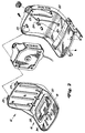
- the safety switch arrangement can be seen in FIGS. 2 to 4 and installed in the driver's seat 12. It causes the vehicle engine to stop immediately when an operator leaves the driver's seat.
- the entire vehicle can be made in plastic.
- the driver's seat 12 which is made of plastic, is of interest.
- It consists in detail of two seat shells 18 and 20, which are produced by injection molding and which accommodate parts of the safety switch arrangement and are later assembled.
- an upholstery 22 can be placed on the first seat shell 18 so that a driver can sit comfortably and safely.
- the second seat shell 20 is located below and behind the first seat shell 18 and a fuel tank, which can be seen in FIG. 2, can still be provided between the two backrests.
- Permanent assembly is achieved by engaging parts 23 and screws on the second seat shell 20, which are to be connected to corresponding openings, such as eyelets 25, on the first seat shell 18.
- the second seat shell 20 receives a switch 24 with a plunger part 26, which are part of the safety circuit.
- the switch 24 is inserted into a corresponding opening in the second seat shell 20 and, as can be seen from FIG. 4, held there by deflectable wing parts 27 which are bent outwards when the switch is inserted and thus hold the switch in a kind of press fit .
- the switch 24 can be wired to the ignition system of the internal combustion engine and can switch off the engine when it switches off.
- the switch acts on other components of a vehicle, such as, for example, on the coupling for the mower 14.
- the switch 24 is designed in such a way that it switches itself off when no operator is in the driver's seat located. It is switched on by a switch flap 28 which is integrated into the first seat shell and which can be bent out, and which is formed during injection molding.
- the switch flap is in a rear horizontal section 30 of the first seat pan 18 is provided movably and is connected to the front part 34 of section 30 via a narrower web on the front. The web functions like a bent part 32 and enables the switch flap to swing down under the weight of a driver.
- the web or bending part 32 allows the switch flap to snap back into its original position when the seat is no longer loaded by the weight of the driver. So that the web can also permanently fulfill this function, it is also provided with stiffening ribs 36, which contribute to the switch flap springing back into its starting position at lightning speed.
- stiffening ribs 36 contribute to the switch flap springing back into its starting position at lightning speed.
- the switch flap can also be designed differently, for example connected to the front part 34 over its entire front width. In such a case, it is then to be designed so flexibly or resiliently that it springs back into its initial position in the unloaded state. If necessary, it can also be made of another material.
- the switch door should be sized and arranged so that the engine continues to run when the operator shifts their seating position from one side to the other of the seat or forward.
- the front part 34 of the horizontal section 30 of the first seat shell 18 is still so large that children who, because of their shorter legs, can usually only sit on the front edge of the seat, cannot engage the switch 24, since their weight then causes the switch flap not reached.
- the switch flap will then bend downwards due to the weight acting on it, as a result of which the plunger is pressed down and the circuit 24 to the ignition system is closed via the switch 24.
- the vehicle can be operated with its units. If the circuit acts on units other than the motor, they can be operated. In such a case, the engine can also be started without the switch 24 closed. It is therefore preferred that the Switch 24 is provided in the circuit for the ignition. If an operator gets off the vehicle without switching off the engine, the switch flap is relieved and jumps back to its starting position due to the inherent flexibility. The switch 24 then immediately turns to its off position, the ignition circuit is interrupted and the vehicle with all its units driven by the engine is switched off.
Landscapes
- Engineering & Computer Science (AREA)
- Transportation (AREA)
- Mechanical Engineering (AREA)
- Aviation & Aerospace Engineering (AREA)
- Chemical & Material Sciences (AREA)
- Combustion & Propulsion (AREA)
- Seats For Vehicles (AREA)
- Push-Button Switches (AREA)
Applications Claiming Priority (2)
| Application Number | Priority Date | Filing Date | Title |
|---|---|---|---|
| US715168 | 1991-06-14 | ||
| US07/715,168 US5162626A (en) | 1991-06-14 | 1991-06-14 | Seat switch mud flap activator integrally mounted to the seat |
Publications (2)
| Publication Number | Publication Date |
|---|---|
| EP0518162A2 true EP0518162A2 (fr) | 1992-12-16 |
| EP0518162A3 EP0518162A3 (en) | 1993-09-08 |
Family
ID=24872934
Family Applications (1)
| Application Number | Title | Priority Date | Filing Date |
|---|---|---|---|
| EP19920109226 Withdrawn EP0518162A3 (en) | 1991-06-14 | 1992-06-02 | Safety switch arrangement for a vehicle |
Country Status (3)
| Country | Link |
|---|---|
| US (1) | US5162626A (fr) |
| EP (1) | EP0518162A3 (fr) |
| CA (1) | CA2070861C (fr) |
Cited By (3)
| Publication number | Priority date | Publication date | Assignee | Title |
|---|---|---|---|---|
| WO2009123773A1 (fr) * | 2008-03-31 | 2009-10-08 | The Boeing Company | Procédés et systèmes pour détecter une activité au moyen de dispositifs de collecte d'énergie |
| ITMI20082159A1 (it) * | 2008-12-05 | 2010-06-06 | Ggp Italy Spa | Dispositivo di sicurezza collegato alla presenza dell'operatore sul sedile di un trattorino |
| US8344912B2 (en) | 2008-03-31 | 2013-01-01 | The Boeing Company | Wireless aircraft sensor network |
Families Citing this family (18)
| Publication number | Priority date | Publication date | Assignee | Title |
|---|---|---|---|---|
| US5424502A (en) * | 1993-07-27 | 1995-06-13 | Delta Systems, Inc. | Quick-install seat switch |
| DE4408481C2 (de) * | 1994-03-14 | 1997-01-23 | Grammer Ag | Sitzplatte, insbesondere für den Fahrersitz eines Nutzfahrzeuges |
| US5565829A (en) * | 1995-04-06 | 1996-10-15 | Clark Equipment Company | Side pivot seat |
| US6359245B1 (en) | 2000-10-18 | 2002-03-19 | Michigan Seat Company | Tractor seat safety system |
| JP4595267B2 (ja) * | 2001-08-29 | 2010-12-08 | アイシン精機株式会社 | 感圧スイッチ |
| US6739116B2 (en) * | 2002-09-13 | 2004-05-25 | The Toro Company | Powered actuator system for mower parking brake system |
| US7582092B2 (en) | 2003-06-25 | 2009-09-01 | Depuy Products, Inc. | Assembly tool for modular implants and associated method |
| US8998919B2 (en) | 2003-06-25 | 2015-04-07 | DePuy Synthes Products, LLC | Assembly tool for modular implants, kit and associated method |
| US7297166B2 (en) | 2003-06-25 | 2007-11-20 | Depuy Products, Inc. | Assembly tool for modular implants and associated method |
| US7726432B2 (en) * | 2007-06-29 | 2010-06-01 | Seats, Inc. | Seat assembly with ignition switch and switch actuator |
| US8556912B2 (en) | 2007-10-30 | 2013-10-15 | DePuy Synthes Products, LLC | Taper disengagement tool |
| US8518050B2 (en) | 2007-10-31 | 2013-08-27 | DePuy Synthes Products, LLC | Modular taper assembly device |
| US20110025109A1 (en) * | 2009-07-31 | 2011-02-03 | Steve Ryczek | Mesh Seat for Ride-On Power Equipment |
| US8533921B2 (en) | 2010-06-15 | 2013-09-17 | DePuy Synthes Products, LLC | Spiral assembly tool |
| US9095452B2 (en) | 2010-09-01 | 2015-08-04 | DePuy Synthes Products, Inc. | Disassembly tool |
| US8393432B2 (en) * | 2011-03-18 | 2013-03-12 | Seats, Inc. | Vehicle seat switch actuator |
| EP2856974B1 (fr) | 2011-04-06 | 2017-03-01 | DePuy Synthes Products, LLC | Alésoir distal |
| US20230249588A1 (en) * | 2022-02-10 | 2023-08-10 | Matthew BAYES | Vehicle seat adjustment system and method |
Family Cites Families (9)
| Publication number | Priority date | Publication date | Assignee | Title |
|---|---|---|---|---|
| US2794089A (en) * | 1954-12-20 | 1957-05-28 | James N Hogg | Switches for automotive vehicles |
| US3736729A (en) * | 1972-02-28 | 1973-06-05 | Cooper Manufacturing Co Inc | Safety interlock system |
| US4198092A (en) * | 1978-05-01 | 1980-04-15 | Fmc Corporation | Seat suspension system |
| US4361741A (en) * | 1980-12-19 | 1982-11-30 | Towmotor Corporation | Switch actuator apparatus |
| US4478307A (en) * | 1981-10-05 | 1984-10-23 | J. I. Case Company | Control handle lockup |
| US4446345A (en) * | 1982-05-19 | 1984-05-01 | Eaton Corporation | Seat switch assembly |
| US4544205A (en) * | 1983-06-16 | 1985-10-01 | Caterpillar Tractor Co. | Seat and self-locking cushion assembly therefor |
| US4795865A (en) * | 1987-12-10 | 1989-01-03 | Delta Systems, Inc. | Safety switch for automatic de-activation of a motor vehicle |
| US4969533A (en) * | 1988-07-29 | 1990-11-13 | Deere & Company | Work vehicle |
-
1991
- 1991-06-14 US US07/715,168 patent/US5162626A/en not_active Expired - Fee Related
-
1992
- 1992-06-02 EP EP19920109226 patent/EP0518162A3/de not_active Withdrawn
- 1992-06-09 CA CA002070861A patent/CA2070861C/fr not_active Expired - Fee Related
Cited By (5)
| Publication number | Priority date | Publication date | Assignee | Title |
|---|---|---|---|---|
| WO2009123773A1 (fr) * | 2008-03-31 | 2009-10-08 | The Boeing Company | Procédés et systèmes pour détecter une activité au moyen de dispositifs de collecte d'énergie |
| US8274383B2 (en) | 2008-03-31 | 2012-09-25 | The Boeing Company | Methods and systems for sensing activity using energy harvesting devices |
| US8344912B2 (en) | 2008-03-31 | 2013-01-01 | The Boeing Company | Wireless aircraft sensor network |
| ITMI20082159A1 (it) * | 2008-12-05 | 2010-06-06 | Ggp Italy Spa | Dispositivo di sicurezza collegato alla presenza dell'operatore sul sedile di un trattorino |
| EP2193703A1 (fr) * | 2008-12-05 | 2010-06-09 | GGP Italy S.p.A. | Dispositif de sécurité basé sur la présence d'un opérateur sur le siège d'un tracteur |
Also Published As
| Publication number | Publication date |
|---|---|
| EP0518162A3 (en) | 1993-09-08 |
| CA2070861A1 (fr) | 1992-12-15 |
| CA2070861C (fr) | 1994-10-18 |
| US5162626A (en) | 1992-11-10 |
Similar Documents
| Publication | Publication Date | Title |
|---|---|---|
| EP0518162A2 (fr) | Dispositif de commutation de securité pour véhicules | |
| DE2335795C3 (de) | Gelenkbeschlag für Fahrzeugsitze | |
| DE69302213T2 (de) | Armlehne für Kraftfahrzeugsitze | |
| DE69302259T2 (de) | Armlehne für Kraftfahrzeugrücksitze | |
| DE69500826T2 (de) | Kindersicherheitssitz für Kraftfahrzeuge | |
| DE10321746B4 (de) | Fahrzeugsitz für Kraftfahrzeuge | |
| DE2708461C3 (de) | Kraftfahrzeugsitz | |
| EP2768697B1 (fr) | Ensemble de verrouillage et de réglage de l'inclinaison, en particulier serrure de dossier | |
| EP3195912B1 (fr) | Vehicule pour enfants | |
| DE69905937T2 (de) | Elektrischer toaster mit einer elektromagnetischen schalteinheit | |
| DE3110689A1 (de) | Sicherheitsgurtanordnung fuer die ruecksitze von kraftfahrzeugen | |
| EP1799494B1 (fr) | Dispositif pour limiter la possibilite de reglage d'un element, en particulier d'un siege de vehicule, a une zone de reglage s'etendant longitudinalement et siege de vehicule | |
| DE60108058T2 (de) | Einziehbare Leiter | |
| DE3425723A1 (de) | Fahrzeugsitz | |
| DE4126518C2 (de) | Fahrzeugsitz | |
| DE19718838B4 (de) | Fahrzeugsitz mit einem Sitzgestell und mit einer im fertiggestellten Zustand an dieses Sitzgestell anmontierbaren Rückenlehne | |
| DE102009009139A1 (de) | Mittelarmlehne für ein Kraftfahrzeug | |
| EP0845384B1 (fr) | Mécanisme de vérrouillage pour le dispositif de déplacement longitudinal de sièges, en particulier de sièges de véhicule automobile | |
| DE1949085C3 (de) | Fahrzeugsitz, insbesondere Kraftfahrzeugsitz | |
| EP0751034B1 (fr) | Siège d'enfants pour véhicules | |
| DE69800043T2 (de) | Antriebsvorrichtung für Rasenmäher | |
| DE2339535C3 (de) | Betätigungshebel für den Rastteil einer Ein- und Feststellvorrichtung von Gelenkbeschlägen für Kraftfahrzeugsitze | |
| EP0236847B1 (fr) | Repose-pieds | |
| WO2023217420A1 (fr) | Système de volet de charge pour un véhicule motorisé | |
| DE29502987U1 (de) | Ausklinkbares Schnappschloß |
Legal Events
| Date | Code | Title | Description |
|---|---|---|---|
| PUAI | Public reference made under article 153(3) epc to a published international application that has entered the european phase |
Free format text: ORIGINAL CODE: 0009012 |
|
| AK | Designated contracting states |
Kind code of ref document: A2 Designated state(s): DE ES FR GB IT SE |
|
| PUAL | Search report despatched |
Free format text: ORIGINAL CODE: 0009013 |
|
| AK | Designated contracting states |
Kind code of ref document: A3 Designated state(s): DE ES FR GB IT SE |
|
| STAA | Information on the status of an ep patent application or granted ep patent |
Free format text: STATUS: THE APPLICATION IS DEEMED TO BE WITHDRAWN |
|
| 18D | Application deemed to be withdrawn |
Effective date: 19940309 |