EP0518199A2 - Querverbindungssystem für B-ISDN - Google Patents
Querverbindungssystem für B-ISDN Download PDFInfo
- Publication number
- EP0518199A2 EP0518199A2 EP92109375A EP92109375A EP0518199A2 EP 0518199 A2 EP0518199 A2 EP 0518199A2 EP 92109375 A EP92109375 A EP 92109375A EP 92109375 A EP92109375 A EP 92109375A EP 0518199 A2 EP0518199 A2 EP 0518199A2
- Authority
- EP
- European Patent Office
- Prior art keywords
- loop
- cell
- monitor cell
- unit
- vpi
- Prior art date
- Legal status (The legal status is an assumption and is not a legal conclusion. Google has not performed a legal analysis and makes no representation as to the accuracy of the status listed.)
- Ceased
Links
Images




Classifications
-
- H—ELECTRICITY
- H04—ELECTRIC COMMUNICATION TECHNIQUE
- H04L—TRANSMISSION OF DIGITAL INFORMATION, e.g. TELEGRAPHIC COMMUNICATION
- H04L49/00—Packet switching elements
- H04L49/10—Packet switching elements characterised by the switching fabric construction
- H04L49/104—Asynchronous transfer mode [ATM] switching fabrics
- H04L49/105—ATM switching elements
- H04L49/107—ATM switching elements using shared medium
-
- H—ELECTRICITY
- H04—ELECTRIC COMMUNICATION TECHNIQUE
- H04L—TRANSMISSION OF DIGITAL INFORMATION, e.g. TELEGRAPHIC COMMUNICATION
- H04L49/00—Packet switching elements
- H04L49/30—Peripheral units, e.g. input or output ports
- H04L49/3009—Header conversion, routing tables or routing tags
-
- H—ELECTRICITY
- H04—ELECTRIC COMMUNICATION TECHNIQUE
- H04L—TRANSMISSION OF DIGITAL INFORMATION, e.g. TELEGRAPHIC COMMUNICATION
- H04L49/00—Packet switching elements
- H04L49/30—Peripheral units, e.g. input or output ports
- H04L49/3081—ATM peripheral units, e.g. policing, insertion or extraction
- H04L49/309—Header conversion, routing tables or routing tags
-
- H—ELECTRICITY
- H04—ELECTRIC COMMUNICATION TECHNIQUE
- H04L—TRANSMISSION OF DIGITAL INFORMATION, e.g. TELEGRAPHIC COMMUNICATION
- H04L49/00—Packet switching elements
- H04L49/55—Prevention, detection or correction of errors
- H04L49/555—Error detection
-
- H—ELECTRICITY
- H04—ELECTRIC COMMUNICATION TECHNIQUE
- H04Q—SELECTING
- H04Q11/00—Selecting arrangements for multiplex systems
- H04Q11/04—Selecting arrangements for multiplex systems for time-division multiplexing
- H04Q11/0428—Integrated services digital network, i.e. systems for transmission of different types of digitised signals, e.g. speech, data, telecentral, television signals
- H04Q11/0478—Provisions for broadband connections
-
- H—ELECTRICITY
- H04—ELECTRIC COMMUNICATION TECHNIQUE
- H04L—TRANSMISSION OF DIGITAL INFORMATION, e.g. TELEGRAPHIC COMMUNICATION
- H04L12/00—Data switching networks
- H04L12/54—Store-and-forward switching systems
- H04L12/56—Packet switching systems
- H04L12/5601—Transfer mode dependent, e.g. ATM
- H04L2012/5603—Access techniques
- H04L2012/5609—Topology
- H04L2012/561—Star, e.g. cross-connect, concentrator, subscriber group equipment, remote electronics
-
- H—ELECTRICITY
- H04—ELECTRIC COMMUNICATION TECHNIQUE
- H04L—TRANSMISSION OF DIGITAL INFORMATION, e.g. TELEGRAPHIC COMMUNICATION
- H04L12/00—Data switching networks
- H04L12/54—Store-and-forward switching systems
- H04L12/56—Packet switching systems
- H04L12/5601—Transfer mode dependent, e.g. ATM
- H04L2012/5625—Operations, administration and maintenance [OAM]
-
- H—ELECTRICITY
- H04—ELECTRIC COMMUNICATION TECHNIQUE
- H04L—TRANSMISSION OF DIGITAL INFORMATION, e.g. TELEGRAPHIC COMMUNICATION
- H04L49/00—Packet switching elements
- H04L49/30—Peripheral units, e.g. input or output ports
Definitions
- the present invention relates to a cross-connection apparatus for B-ISDN (Broadband-Integrated Service Digital Network), more particularly, it relates to a cross-connection apparatus having a monitor function using a monitor cell which is inserted therein and extracted therefrom.
- B-ISDN Broadband-Integrated Service Digital Network
- B-ISDN has been developed and widely utilized as a high speed and broadband information processing network enabling, so-called, multi media service.
- a fixed length packet is used to transfer the information in this type of network.
- an ATM (Asynchronous Transfer Mode) network has been developed as a technique easily realizing a B-ISDN.
- ATM Asynchronous Transfer Mode
- ATM cells are used as the above fixed length packets rather than STM (Synchronous Transfer Mode) method, because the ATM cells are suitable for the control of a distributed processing since it is not necessary to perform an allocation of time slots when transferring information. Accordingly, the ATM network can easily realize the multi media service.
- a monitor cell is used for the above.
- An OAM (Operation, Administration and Maintenance) cell is used as the monitor cell in the B-ISDN as explained in detail below.
- the object of the present invention is to provide a cross-connection apparatus enabling easy monitoring of an operation of the apparatus.
- a cross-connection apparatus for B-ISDN including: plural interface units, each having a reception port for receiving a fixed length packet or inserting a monitor cell, and a transmission port for transferring the fixed length packet or extracting the monitor cell; plural multiplexers, each operatively connected to corresponding interface unit for multiplexing the fixed length packet or the monitor cell; plural virtual path identifier (VPI) conversion tables, each operatively connected to corresponding multiplexer for converting the VPI to change a transmission route of the fixed length packet or the monitor cell; a switch unit operatively connected to the VPI conversion tables for switching the transmission route of the fixed length packet or the monitor cell based on the VPI; plural demultiplexers operatively connected to the switch unit for demultiplexing the fixed length packet or the monitor cell and transferring these cells to the transmission port; and plural loop-back units operatively connected to corresponding interface unit for changing the transmission route so as to transfer the monitor cell to the same interface unit which said monitor cell is inserted, and
- the fixed length packet is an ATM (Asynchronous Transfer Mode) cell.
- the monitor cell is an OAM cell including a header area and a payload area, the header area having information of the VPI and the transmission route, and the payload area having loop-back information written at insertion to the reception port and rewritten in the loop-back unit.
- the loop-back unit is further provided between the multiplexer and the demultiplexer so as to bypass the VPI conversion table and the switch unit.
- the loop-back unit includes: four input/output ports, i.e., two input ports and two output ports; an extraction unit receiving the monitor cell from the input port 2 and extracting the monitor cell to be loop-backed; and a write unit operatively connected to the extraction unit to receive the monitor cell to be loop-backed for writing an information of a passage point of the monitor cell on the transmission route and outputting the information to the output port 1.
- the extraction unit includes: a detection unit connected to the input port 2 for detecting the monitor cell and extracting counter values indicating numbers passed through the loop-back means, i.e., passage counter values; an update unit receiving the passage counter values to update them and generating two kinds of control signals to switch the transmission route; an insertion unit for inserting the updated passage counter values into the monitor cell based on the control signal S1; and a switch unit for switching the transmission route of the monitor cell between the output port 2 and the loop-back port based on the control signal S2.
- the header area includes an OAM cell discriminator for defining the OAM cell, a loop-back cell discriminator for defining the loop-back, and an output designating value for designating an address of the interface unit outputting the OAM cell.
- the payload area includes an insertion point discrimination for recording the discriminator of the insertion point; a passage counter value for designating the number of the loop-back unit i.e., loop-back point, to perform loop-back operation; a new output designating value set so as to output to the insertion point of the OAM cell, and copied to the output designating value of the header area in the first loop-back unit; a loop-back point discriminator for indicating a space to insert the discriminator of the loop-back unit which has already performed loop-back operation; and data for monitoring error rate.
- Figure 1 shows the basic structure of an ATM cell.
- the ATM cell is formed by a header area H having five bytes and a payload area P having forty-eight bytes.
- the header area H is formed by a virtual path identifier area VPI having twelve bits for identifying a virtual path VP, a virtual channel identifier area VCI for identifying a virtual channel, a payload type area PT for identifying a monitor cell, and remainder area.
- FIG. 2 shows one example of an ATM network.
- reference numbers 1a to 3a denote cross-connection apparatuses
- 1b to 4b denote terminal equipments.
- thin lines denote virtual paths (VP)
- thick lines denote high speed transmission lines (TL) connecting between cross-connection apparatuses.
- Each of terminal equipments 1b to 4b is connected to a corresponding cross-connecting apparatus through the high speed transmission line TL.
- the virtual path VP is provided for indicating the allocation of high speed transmission lines between any two terminal equipments. Accordingly, the virtual path identifier VPI shown in Fig. 1 is used to identify the virtual path VP.
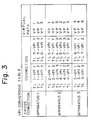
- Figure 3 shows a VPI conversion table provided in the cross-connection apparatus.
- a virtual path identifier VPI is individually set to each transmission line TL in each cross-connection apparatus, and the connection relationship between the transmission line and the virtual path identifier VPI is set to the corresponding virtual path VP. Accordingly, the transmission route of the ATM cell and the monitor cell is selected in the cross-connection apparatus based on the virtual path identifier VPI.
- a monitor cell is provided in the payload type area PT in the header area H shown in Fig. 1 to periodically monitor the transfer state of the ATM cell in the cross-connection apparatus to determine whether or not it is transferred normally through the virtual path VP.
- an OAM cell is used as a monitor cell in the ATM network.
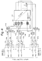
- FIG. 4 is a schematic block diagram for explaining the transfer of the ATM cell and the OAM cell in a conventional cross-connection apparatus for the ATM network.
- reference numbers 10-1 to 10-N denote interface units each having a reception port (RP) 10a and a transmission port (TP) 10b.
- the reception port 10a receives the ATM cell as a main signal (MS) and periodically inserts the OAM cell C.
- the transmission port 10b transfers the ATM cell as a main signal (MS) and extracts the OAM cell C.
- Reference numbers 11-1a, 11-2a and 11-Na denote multiplexers (MUXs) each multiplexing the ATM cell or the OAM cell.
- Reference numbers 11-1b, 11-2b and 11-Nb denote demultiplexers (DMUXs) each demultiplexing the multiplexed ATM cell or the OAM cell.
- Reference numbers 12-1 to 12-N denote VPI conversion tables each converting the VPI of the header area H of the OAM cell into the VPI for the next transmission route.
- Reference number 13 denotes a switch unit for switching the transmission route based on the converted VPI of the header area H of the OAM cell.
- the OAM cell is inserted to the reception port 10a of the interface 10-1, transferred to the multiplexer 11-1a, transferred to the switch unit 13 after conversion of the VPI in the VPI conversion table, transferred to the demultiplexer 11-Nb, and finally, transferred to the transmission port 10b of the interface 10-N and output therefrom.
- Figures 5A and 5B are detailed block diagrams of the reception port and the transmission port shown in Fig. 4.
- Figure 5A denotes the reception port
- Figure 5B denotes the transmission port.
- reference number 101 denotes a monitor cell insertion unit for inserting the OAM cell when monitoring the apparatus
- 102 denotes an ATM receiving/processing unit for receiving the ATM cell from the other cross-connection apparatus
- 103 denotes a selection unit (SEL) for selecting between the ATM cell and the OAM cell.
- reference number 104 denotes a monitor cell extraction unit for extracting the OAM cell when it is transferred from the demultiplexer DMUX and outputting the OAM cell
- 105 denotes an ATM transmitting/processing unit.
- the OAM cell When checking the cross-connection apparatuses, the OAM cell is inserted to the monitor cell insertion unit 101 of the reception port 10a from the terminal equipment. When inserting the OAM cell, it is multiplexed by the multiplexer MUX and transferred to the switch unit 13 after conversion of the VPI in the VPI conversion table. Further, the OAM cell is input from the demultiplexer DMUX to the monitor cell extracting unit 104 so that the OAM cell is extracted.
- the interface unit into which the OAM is periodically inserted to monitor the apparatus is different from the interface unit which the OAM cell is extracted. That is, the OAM cell is inserted into the interface unit 10a, and is extracted from the interface unit 10N. Accordingly, it is necessary to monitor the OAM cell for two interface units so that the monitor step becomes complex and much time is required to monitor the cross-connection apparatus.
- the feature of the present invention is to provide a cross-connection apparatus enabling easy monitoring of the apparatus in such a way that the same monitor cell is inserted into and extracted from the same interface unit.
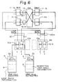
- FIG. 6 is a schematic block diagram of a cross-connection apparatus according to an embodiment of the present invention.
- reference numbers 10a to 10N denote interface units
- 11-1a to 11-Na denote multiplexers
- 11-1b to 11-Nb denote demultiplexers
- 12-1 to 12-N denote VPI conversion tables
- 13 denotes switch unit
- 20-1 to 20-N denote loop-back units.
- each loop-back unit 20-1 to 20-N is provided for each corresponding interface units 10-1 to 10-N.
- the OAM cell to be inserted (below, OAM cell Ca) is input to the reception port 10a, and the OAM cell to be extracted (below, OAM cell Cb) is output from the transmission unit 10b in the same interface unit.
- the OAM cell has information for the VPI and the transmission route in the header area H, and the information for the loop-back route in the payload area P.
- the OAM cell Ca When the OAM cell Ca is inserted into the reception port 10a of the interface 10-1, the OAM cell Ca is transferred to the multiplexer 11-1a through the loop-back unit 20-1. Further, the OAM cell is transferred to the switch unit 13 through the VPI conversion table 12-1. The route of the OAM cell Ca is changed to the other route in the switch unit 13 based on the VPI conversion table 12-1.
- the OAM cell Ca is transferred to the loop-back unit 20-N through the demultiplexer 11-Nb.
- the loop-back unit 20-N performs a loop-back operation after rewriting the loop-back information of the payload area P as explained in detail herein after, and generates a rewritten OAM cell Cb. Accordingly, when the OAM cell Ca reaches to the loop-back unit 20-N, a new OAM cell Cb, for which loop-back information is rewritten, is transferred from the interface unit 20-N to the multiplexer 11-Na. That is, the OAM cell is not transferred to the interface unit 10-N.
- the OAM cell Cb is transferred from the interface unit 10-N to the multiplexer 11-Na, and transferred to the switch unit 13 through the VPI conversion table 12-N, which performs a further VPI conversion. Then, the transmission route of the OAM cell Cb is changed by the switch unit 13, and transferred to the loop-back unit 20-1 through the demultiplexer 11-1b. Finally, the OAM cell Cb is transferred to the transmission port 10b of the same interface unit 10-1 into which the OAM cell is inserted and the OAM cell Cb is extracted therefrom.
- the loop-back information of the OAM cell Ca is rewritten by the loop-back unit 20-N so that the OAM cell Ca becomes the OAM cell Cb having the rewritten loop-back information. Accordingly, the original loop-back information of the OAM cell Ca is compared with the rewritten loop-back information of the OAM cell Cb so that it is possible to determine whether or not the cross-connection apparatus is operating normally.
- FIG. 7 is a schematic block diagram of a cross-connection apparatus according to another embodiment of the present invention.
- the same reference numbers as used in Fig. 6 are attached to the same components in this drawing.
- Reference numbers 30-1 and 30-N denote loop-back units in addition to the loop-back units 20-1 and 20-N.
- a plurality of the loop-back units 20-1 to 20-N and 30-1 to 30-N are provided in the transmission route.
- the loop-back unit 30-1 directly connects the multiplexer 11-1a and the demultiplexer 11-1b so as to bypass the VPI conversion table 12-1 and the switch unit 13. Accordingly, the VPI conversion table 12-1 is not used for converting the transmission route.
- the loop-back units 20-1 to 20-N are not used for a loop-back operation.
- the OAM cell Ca is inserted into the reception port 10a of the interface unit 10-1 and transferred to the multiplexer 11-1a through the loop-back unit 20-1. Further, the OAM cell is transferred to the demultiplexer 11-1b through the loop-back unit 30-1, then, the OAM cell is transferred to the transmission port 10b of the same interface unit 10-1 through the same loop-back unit 20-1.
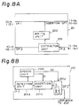
- Figure 8A is a detailed structure of the loop-back unit shown in Figs. 7 and 8, and Figure 8B is a detailed structure of an extraction unit in Fig. 8A.
- the loop-back unit is formed by four input/output ports, i.e., two input ports IP1 and IP2 and two output ports OP1 and OP2; an extraction unit 201 receiving the monitor cell from the input port 2 and extracting the monitor cell to be loop-backed; and write unit 202 operatively connected to the extraction unit to receive the monitor cell to be loop-backed for writing information of the passage point of the monitor cell on the transmission route and outputting the information to the output port 1.
- the extraction unit 201 is formed by a detection unit 201a connected to the input port 2 for detecting the monitor cell and extracting counter values indicating the numbers passed through the loop-back means, i.e., passage counter values; an update unit 201b receiving the passage counter values to update them and generating two kinds of control signals S1 and S2 to switch the transmission route; an insertion unit 201c for inserting the updated passage counter values into the monitor cell based on the control signal S1; and a switch unit 201d for switching the transmission route of the monitor cell between the output port 2 and the loop-back port based on the control signal S2.
- a detection unit 201a connected to the input port 2 for detecting the monitor cell and extracting counter values indicating the numbers passed through the loop-back means, i.e., passage counter values
- an update unit 201b receiving the passage counter values to update them and generating two kinds of control signals S1 and S2 to switch the transmission route
- an insertion unit 201c for inserting the updated passage counter values into the monitor cell
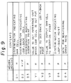
- Figure 9 shows loop-back information of the OAM cell when it is inserted into the reception port of the interface unit 10-1 shown in Figs. 6 and 7.
- H denotes the header area of the OAM cell
- P denotes the payload area of the OAM cell as mentioned above.
- the header area H includes an OAM cell discriminator D1 for defining the OAM cell, a loop-back cell discriminator D2 for defining the loop-back cell, and an output designating value V1 (i.e., VPI etc) for designating an address of the interface unit outputting the OAM cell.
- V1 i.e., VPI etc
- the loop-back cell discriminator D2 is also included in the payload area P.
- the payload area P includes an insertion point discriminator D3 for recording the discrimination number of the insertion point (interface unit to be inserted); a passage counter value V2 for designating a loop-back unit number to perform a loop-back operation (i.e., a loop-back point); a new output designating value V3 (i.e., VPI) set so as to output to the insertion point of the OAM cell, and this value is copied to the output designating value V1 of the header area H in the first loop-back unit; a loop-back point discriminator D4 for indicating a space to insert the discriminator of the loop-back unit which has already performed the loop-back operation; and data DA for monitoring error rate, for example, a pseudo noise (PN) pattern.
- PN pseudo noise
- new output designating value V3 is set as a new value in the loop-back unit which performs the loop-back operation, and this value V3 is copied to the header area H after loop-back operation. Accordingly, since this new value V3 does not have an effective value for the loop-back point discriminator D4 in the same timing, it is possible to hold this new value V3 and the loop-back point discriminator D4 in the same area.
- the OAM cell When the OAM cell is inserted into the reception port 10a of the interface unit 10-1 shown in Fig. 6, the OAM cell is transferred to the multiplexer 11-1a through the loop-back unit 20-1. This corresponds to the thick line from the input port 1 (IP1) to the output port 1 (OP1) in Fig. 8A.
- IP1 input port 1
- OP1 output port 1
- the OAM cell is transferred to the VPI conversion table 12-1 through the multiplexer 11-1a, the output port number of the switch unit 13 is determined based on the output designating value V1 shown in Fig. 9. Then, the OAM cell is transferred from the output port of the switch unit 13, which is determined by the output designating value V1, to the loop-back unit 20-N through the demultiplexer 11-Nb.
- the OAM cell is input from the input port 2 (IP2) shown in Fig. 8A, and transferred to the extraction unit 201.
- the OAM cell detection unit 201a detects the OAM cell based on the OAM cell discriminator D1 of the header area H, extracts the passage counter value V2 of the payload area P, and outputs this counter value V2 to the update unit 201b.
- the counter value V2 is decremented by "1", and this decremented value is transferred to the insertion unit 201c. Accordingly, the counter value V2 of the OAM cell passing through the insertion unit 201c is always decremented by "1" from the input counter value, and this decremented value is transferred to the switch unit 201d.
- the switch unit 201d determines whether or not the loop-back operation is performed based on the counter value updated by the update unit 201b. That is, for example, in the case of the loop-back route shown in Fig. 6, the passage counter value V2 of the OAM cell shown in Fig. 9 is determined so as to become the same value as the output designating value V1. Accordingly, when the counter value is decremented by "1" in the update unit 201b when the OAM cell passes through the loop-back unit 20-1, and the passage counter value V2 becomes "0" when the OAM cell reaches the loop-back unit 20-N. When the passage counter value V2 becomes "0", the update unit 201b generates the control signal to the switch unit 201d to switch the transmission route to the loop-back route.
- the OAM cell is transferred from the input port 2 (IP2) to the extraction unit 201, and is further transferred to the write unit 202.
- the loop-back point discriminator D4 which indicates passage point, is written to the payload area P so that the OAM cell is transferred to the multiplexer 11-Na through the input port 1 (IP1).
- the OAM cell is transferred from the multiplexer 11-Na to the VPI conversion table 12-N.
- a new output designating value V3 indicating the above operation is set to the payload P of the OAM cell. That is, as explained above, when it is previously known that the OAM cell again passes through the VPI conversion table after a loop-back operation, the new output designating value V3 denotes the output designating value determined so as to output to the insertion point of the OAM cell, and this new output designating value V3 is copied to the output designating value V1 of the header area H in the first loop-back unit.
- the VPI conversion of the OAM cell is performed to the VPI conversion table 12-N in accordance with the new output designating value V3 so that, as shown in Fig. 6, the OAM cell is transferred to the demultiplexer 11-1b through the switch unit 13, and further transferred to the first interface 10-1 through the loop-back unit 20-1.
- the OAM cell can be returned to the same interface 20-1 into which the OAM cell is inserted.
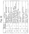
- Figure 10 shows loop-back information of the OAM cell when it is extracted from the transmission port of the interface unit 10-1 shown in Figs. 6 and 7.
- the new output designating value V3 which is set in the insertion step is written to the output designating value V1 of the header area H so that the new output designating value V3 is changed.
- the OAM cell is input from the demultiplexer 11-Nb to the input port 2 (IP2) shown in Fig. 8A.
- the extraction unit 201 shown in Fig. 8B since the passage counter value V2 becomes "0", the OAM cell is transferred from the switch unit 201d to the output port 2 (OP2) so that the loop-back operation is not performed in this loop-back unit 20-1. Accordingly, the OAM cell is transferred to the transmission port 10b of the same interface unit 10-1, and it is extracted therefrom.
- the inserted OAM cell shown in Fig. 9 is compared with the extracted OAM cell shown in Fig. 10 so that it is possible to easily check an operation of the cross-connection apparatus.
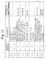
- Figure 11 shows data of the OAM cell for judging failure of the cross-connection apparatus. The judgement is performed based on the following facts, and the error portion is estimated based on the result of the judgement. First, it is determined whether the OAM cell discriminator D1 indicates the OAM cell, and then it is determined whether the loop-back cell discriminator indicates the loop-back cell.
- the error portion in the apparatus is estimated when each of the above items is not satisfied as follows. That is, in the case of item (1), the error portion is estimated as the VPI conversion table 12, the switch unit 13 and the OAM cell insertion port 10a. In the case of item (2), the error portion is estimated as the VPI conversion table 12 and the loop-back point 20 and 30. In the case of item (3), the error portion is estimated as the loop-back point 20 and 30. In the case of item (5), the error portion is estimated as the VPI conversion table 12, the switch unit 13 and the OAM cell insertion port 10a. In the case of item (6), the error portion is estimated as the data error on the transmission route.
- the OAM cell is transferred from the input port 2 (IP2) to the extraction unit 201 of the loop-back unit 30-1 through the multiplexer 11-1a (indicated by (11-1a) in Fig. 8A), and transferred to the output port 1 (OP1) through the write unit 202 (indicated by (11-1b) in Fig. 8A). Further, the OAM cell is transferred from the demultiplexer 11-1b to the interface 10-1 through the loop-back unit 20-1. Accordingly, as explained in Fig. 7, the OAM cell does not pass the VPI conversion table after the loop-back operation.
- a monitor cell i.e., OAM cell
- the monitor cell has predetermined loop-back information in the payload area thereof.
- the loop-back information is rewritten in the loop-back unit when the OAM cell passes therethrough, and the loop-back information of the inserted OAM cell is compared with that of the extracted OAM cell so that the function of the cross-connection apparatus is checked based on the above comparison. Accordingly, it is possible to easily monitor the function of the cross-connection apparatus in a B-ISDN.
Landscapes
- Engineering & Computer Science (AREA)
- Computer Networks & Wireless Communication (AREA)
- Signal Processing (AREA)
- Data Exchanges In Wide-Area Networks (AREA)
Applications Claiming Priority (2)
| Application Number | Priority Date | Filing Date | Title |
|---|---|---|---|
| JP160037/91 | 1991-06-03 | ||
| JP16003791A JP3025060B2 (ja) | 1991-06-03 | 1991-06-03 | 装置監視方式 |
Publications (2)
| Publication Number | Publication Date |
|---|---|
| EP0518199A2 true EP0518199A2 (de) | 1992-12-16 |
| EP0518199A3 EP0518199A3 (en) | 1997-01-15 |
Family
ID=15706576
Family Applications (1)
| Application Number | Title | Priority Date | Filing Date |
|---|---|---|---|
| EP92109375A Ceased EP0518199A3 (en) | 1991-06-03 | 1992-06-03 | A cross-connection apparatus for b-isdn |
Country Status (4)
| Country | Link |
|---|---|
| US (1) | US5265088A (de) |
| EP (1) | EP0518199A3 (de) |
| JP (1) | JP3025060B2 (de) |
| CA (1) | CA2069832C (de) |
Cited By (10)
| Publication number | Priority date | Publication date | Assignee | Title |
|---|---|---|---|---|
| EP0619661A1 (de) * | 1993-04-08 | 1994-10-12 | Alcatel STR AG | Belastungsprüfung einer ATM-Vermittlungsstelle |
| FR2706712A1 (fr) * | 1993-06-11 | 1994-12-23 | Girard Alain | Système de commutation temporelle destiné à un réseau de transmission de cellules. |
| GB2285366A (en) * | 1993-12-30 | 1995-07-05 | Samsung Electronics Co Ltd | Asynchronous data transfer |
| US5872770A (en) * | 1995-12-21 | 1999-02-16 | Electronics And Telecommunications Research Institute | Received asynchronous transfer mode layer operation and maintenance cell processing apparatus |
| EP0719067A3 (de) * | 1994-12-23 | 1999-03-10 | Philips Patentverwaltung GmbH | Übertragungssystem |
| WO1999001009A3 (en) * | 1997-06-27 | 1999-03-18 | Nokia Telecommunications Oy | Processing of signalling messages in atm node |
| EP0866631A3 (de) * | 1997-03-19 | 1999-12-22 | Fujitsu Limited | Vorrichtung zum Abschliessen von mehreren Leitungen und dessen "OAM" Verfahren |
| CN100369417C (zh) * | 1998-08-06 | 2008-02-13 | 富士通株式会社 | 固定长度数据处理设备 |
| EP2544409A1 (de) * | 2011-07-04 | 2013-01-09 | Telefonaktiebolaget L M Ericsson AB (Publ) | Generischer Überwachungs-Pakethandhabungsmechanismus für OpenFlow 1.1 |
| EP3389224A1 (de) * | 2017-04-13 | 2018-10-17 | Bull SAS | Verfahren zur erzeugung und kontrolle eines test-datenverkehrs, entsprechender eingangs- oder ausgangsanschluss eines schalters und entsprechender schalter |
Families Citing this family (27)
| Publication number | Priority date | Publication date | Assignee | Title |
|---|---|---|---|---|
| JPH05252184A (ja) * | 1992-03-06 | 1993-09-28 | Hitachi Ltd | バーチャルパス接続装置およびバーチャルパストレース方法 |
| US5577032A (en) * | 1992-09-11 | 1996-11-19 | Fujitsu Limited | Broadcast service system |
| DE4230743C2 (de) * | 1992-09-14 | 1994-03-17 | Siemens Ag | Verfahren zum Rundsenden von Zellen in einer im Asynchron-Transfer-Modus wirkenden Koppelstruktur eines Kommunikationssystems |
| WO1994009576A1 (en) * | 1992-10-21 | 1994-04-28 | Bell Communications Research, Inc. | A broadband virtual private network service and system |
| JP2953924B2 (ja) * | 1992-10-21 | 1999-09-27 | 日本電気株式会社 | パケット通信における私設網構成方法およびシステム |
| DE4308174C1 (de) * | 1993-03-15 | 1994-03-24 | Siemens Ag | Verfahren für Punkt-zu-Mehrpunkt-Verbindungen in selbstroutenden ATM-Koppelfeldern |
| US5442628A (en) * | 1993-11-15 | 1995-08-15 | Motorola, Inc. | Local area network data processing system containing a quad elastic buffer and layer management (ELM) integrated circuit and method of switching |
| US6005844A (en) * | 1994-10-03 | 1999-12-21 | Fujitsu Limited | Information collection device and method for use with communications networks |
| JP3452657B2 (ja) * | 1994-10-03 | 2003-09-29 | 富士通株式会社 | 通信ネットワークにおける情報収集装置および方法 |
| JP2738344B2 (ja) * | 1995-05-29 | 1998-04-08 | 日本電気株式会社 | Atmセルループバック方式 |
| US5787086A (en) * | 1995-07-19 | 1998-07-28 | Fujitsu Network Communications, Inc. | Method and apparatus for emulating a circuit connection in a cell based communications network |
| JP3171773B2 (ja) * | 1995-08-31 | 2001-06-04 | 富士通株式会社 | 交換機におけるコネクション制御方法及び装置 |
| US5712853A (en) * | 1995-09-11 | 1998-01-27 | General Datacomm, Inc. | Apparatus and method for transferring operation, administration and management cells across and ATM data frame user network interface |
| AU6970896A (en) * | 1995-09-14 | 1997-04-01 | Ascom Nexion Inc. | Transmitter controlled flow control for buffer allocation in wide area atm networks |
| JP3264803B2 (ja) * | 1995-09-25 | 2002-03-11 | 富士通株式会社 | 固定長セルをサポートしたアド・ドロップ多重化装置 |
| US5812528A (en) * | 1995-11-17 | 1998-09-22 | Telecommunications Techniques Corporation | Measuring round trip time in ATM network virtual connections |
| US5659540A (en) * | 1995-12-15 | 1997-08-19 | General Datacomm, Inc. | Apparatus and method for detection of operation administration and management (OAM) cell loopback and physical loopbacks in an asynchronous transfer mode (ATM) network |
| AU1697697A (en) * | 1996-01-16 | 1997-08-11 | Fujitsu Limited | A reliable and flexible multicast mechanism for atm networks |
| US5748905A (en) * | 1996-08-30 | 1998-05-05 | Fujitsu Network Communications, Inc. | Frame classification using classification keys |
| TW353838B (en) * | 1996-11-12 | 1999-03-01 | Toshiba Corp | Ring network system and control method of its communication path |
| JPH11122261A (ja) | 1997-10-17 | 1999-04-30 | Fujitsu Ltd | Atm交換機の装置内導通試験装置 |
| KR100297590B1 (ko) * | 1998-09-18 | 2001-08-07 | 서평원 | 교환기에서 스위치 네트워크의 경로 시험 방법 |
| JP3482996B2 (ja) | 1999-12-03 | 2004-01-06 | 日本電気株式会社 | Atmスイッチ |
| US6977922B2 (en) * | 2000-10-02 | 2005-12-20 | Paradyne Corporation | Systems and methods for automatically configuring cross-connections in a digital subscriber line access multiplexer (DSLAM) |
| US6894970B1 (en) * | 2000-10-31 | 2005-05-17 | Chiaro Networks, Ltd. | Router switch fabric protection using forward error correction |
| ATE405070T1 (de) * | 2002-04-11 | 2008-08-15 | Nxp Bv | Synchronisierung von zellenübertragung in einer paketvermittlungsstelle |
| US9419903B2 (en) * | 2012-11-08 | 2016-08-16 | Texas Instruments Incorporated | Structure for implementing openflow all group buckets using egress flow table entries |
Family Cites Families (5)
| Publication number | Priority date | Publication date | Assignee | Title |
|---|---|---|---|---|
| US4551830A (en) * | 1984-03-19 | 1985-11-05 | Rockwell International Corporation | Apparatus for providing loopback of signals where the signals being looped back have an overhead data format which is incompatible with a high speed intermediate carrier overhead format |
| US4745593A (en) * | 1986-11-17 | 1988-05-17 | American Telephone And Telegraph Company, At&T Bell Laboratories | Arrangement for testing packet switching networks |
| JPS63283345A (ja) * | 1987-05-15 | 1988-11-21 | Nec Corp | クロスコネクト装置の診断方式 |
| JP2753294B2 (ja) * | 1988-12-23 | 1998-05-18 | 株式会社日立製作所 | パケット輻輳制御方法およびパケット交換装置 |
| JP2834253B2 (ja) * | 1990-02-07 | 1998-12-09 | 株式会社日立製作所 | パケツト交換機 |
-
1991
- 1991-06-03 JP JP16003791A patent/JP3025060B2/ja not_active Expired - Fee Related
-
1992
- 1992-05-28 CA CA002069832A patent/CA2069832C/en not_active Expired - Fee Related
- 1992-06-02 US US07/889,924 patent/US5265088A/en not_active Expired - Lifetime
- 1992-06-03 EP EP92109375A patent/EP0518199A3/en not_active Ceased
Cited By (17)
| Publication number | Priority date | Publication date | Assignee | Title |
|---|---|---|---|---|
| EP0619661A1 (de) * | 1993-04-08 | 1994-10-12 | Alcatel STR AG | Belastungsprüfung einer ATM-Vermittlungsstelle |
| US5504754A (en) * | 1993-04-08 | 1996-04-02 | Alcatel Str A.G. | Method and arrangement for the load testing of a switch for cell structured digital data |
| FR2706712A1 (fr) * | 1993-06-11 | 1994-12-23 | Girard Alain | Système de commutation temporelle destiné à un réseau de transmission de cellules. |
| GB2285366A (en) * | 1993-12-30 | 1995-07-05 | Samsung Electronics Co Ltd | Asynchronous data transfer |
| GB2285366B (en) * | 1993-12-30 | 1998-07-15 | Samsung Electronics Co Ltd | Asychronous data transfer |
| EP0719067A3 (de) * | 1994-12-23 | 1999-03-10 | Philips Patentverwaltung GmbH | Übertragungssystem |
| US6163529A (en) * | 1994-12-23 | 2000-12-19 | U.S. Philips Corporation | Transmission system with line status determination independent of received packet order |
| US5872770A (en) * | 1995-12-21 | 1999-02-16 | Electronics And Telecommunications Research Institute | Received asynchronous transfer mode layer operation and maintenance cell processing apparatus |
| EP0866631A3 (de) * | 1997-03-19 | 1999-12-22 | Fujitsu Limited | Vorrichtung zum Abschliessen von mehreren Leitungen und dessen "OAM" Verfahren |
| US6198726B1 (en) | 1997-03-19 | 2001-03-06 | Fujitsu Limited | Plural-line terminating apparatus and OAM processing method thereof |
| WO1999001009A3 (en) * | 1997-06-27 | 1999-03-18 | Nokia Telecommunications Oy | Processing of signalling messages in atm node |
| US6731641B1 (en) | 1997-06-27 | 2004-05-04 | Nokia Corporation | Processing of signalling messages in ATM node |
| CN100369417C (zh) * | 1998-08-06 | 2008-02-13 | 富士通株式会社 | 固定长度数据处理设备 |
| EP2544409A1 (de) * | 2011-07-04 | 2013-01-09 | Telefonaktiebolaget L M Ericsson AB (Publ) | Generischer Überwachungs-Pakethandhabungsmechanismus für OpenFlow 1.1 |
| EP3389224A1 (de) * | 2017-04-13 | 2018-10-17 | Bull SAS | Verfahren zur erzeugung und kontrolle eines test-datenverkehrs, entsprechender eingangs- oder ausgangsanschluss eines schalters und entsprechender schalter |
| FR3065302A1 (fr) * | 2017-04-13 | 2018-10-19 | Bull Sas | Procede de generation et de controle de trafic de test, port d'entree ou de sortie de commutateur et commutateur associes |
| US11621906B2 (en) | 2017-04-13 | 2023-04-04 | Bull Sas | Method for test traffic generation and inspection, and associated switch input or output port and switch |
Also Published As
| Publication number | Publication date |
|---|---|
| CA2069832C (en) | 1994-11-15 |
| JP3025060B2 (ja) | 2000-03-27 |
| EP0518199A3 (en) | 1997-01-15 |
| JPH0530128A (ja) | 1993-02-05 |
| US5265088A (en) | 1993-11-23 |
Similar Documents
| Publication | Publication Date | Title |
|---|---|---|
| US5265088A (en) | Cross-connection apparatus for B-ISDN | |
| US6229822B1 (en) | Communications system for receiving and transmitting data cells | |
| US5313453A (en) | Apparatus for testing ATM channels | |
| EP1045557B1 (de) | ATM Übermittlungssystem | |
| EP0674457B1 (de) | Vermittlungseinrichtung | |
| US5715239A (en) | ATM multiplex transmission system having test equipment | |
| JP2892180B2 (ja) | Atmクロスコネクト装置の監視方式 | |
| CA2056652C (en) | Telephone subscriber accommodation system in a broadband network | |
| EP0468498B1 (de) | Leitweglenkungssystem mit Eignung zur effektiven Verarbeitung der Leitweglenkungsinformation | |
| US5805568A (en) | Add/drop multiplexer for supporting fixed length cell | |
| CA2268563C (en) | Atm transmission equipment | |
| EP0674409B1 (de) | Gerät zum Testen von ATM-Vermittlungskanälen | |
| RU2134024C1 (ru) | Устройство и способ обработки элементов данных режима асинхронной передачи в системе коммутации режима асинхронной передачи | |
| US5608719A (en) | ATM multiplex transmission system having test equipment | |
| JP2824483B2 (ja) | Atm交換機におけるスイッチ診断方式 | |
| JP2639345B2 (ja) | Atmスイッチ試験装置 | |
| KR100236605B1 (ko) | Atm 접속카드의 atm 망 접속을 위한 셀 다중화장치 | |
| JPH0918490A (ja) | 制御回線多重化装置 | |
| JP3005553B1 (ja) | Aal1−sar機能の試験方法及び装置 | |
| JPH0522404A (ja) | Stm−atm相互変換制御方式 | |
| WO1999018752A1 (en) | System and method for telecommunications bus control | |
| JPH04310033A (ja) | Atmクロスコネクト装置 | |
| JPH05327757A (ja) | 監視セル挿入制御方式 | |
| KR20000028082A (ko) | 사설 교환기의 셀 스위칭 장치 및 방법 | |
| JP2000049796A (ja) | 通信システムおよびそのoamセル転送方法 |
Legal Events
| Date | Code | Title | Description |
|---|---|---|---|
| PUAI | Public reference made under article 153(3) epc to a published international application that has entered the european phase |
Free format text: ORIGINAL CODE: 0009012 |
|
| AK | Designated contracting states |
Kind code of ref document: A2 Designated state(s): DE FR GB |
|
| PUAL | Search report despatched |
Free format text: ORIGINAL CODE: 0009013 |
|
| AK | Designated contracting states |
Kind code of ref document: A3 Designated state(s): DE FR GB |
|
| 17P | Request for examination filed |
Effective date: 19970711 |
|
| 17Q | First examination report despatched |
Effective date: 19991216 |
|
| GRAG | Despatch of communication of intention to grant |
Free format text: ORIGINAL CODE: EPIDOS AGRA |
|
| STAA | Information on the status of an ep patent application or granted ep patent |
Free format text: STATUS: THE APPLICATION HAS BEEN REFUSED |
|
| 18R | Application refused |
Effective date: 20010917 |