EP0518217A1 - Presse pour bois à lames pour la fabrication de poutres fermes collées et arguées - Google Patents
Presse pour bois à lames pour la fabrication de poutres fermes collées et arguées Download PDFInfo
- Publication number
- EP0518217A1 EP0518217A1 EP92109471A EP92109471A EP0518217A1 EP 0518217 A1 EP0518217 A1 EP 0518217A1 EP 92109471 A EP92109471 A EP 92109471A EP 92109471 A EP92109471 A EP 92109471A EP 0518217 A1 EP0518217 A1 EP 0518217A1
- Authority
- EP
- European Patent Office
- Prior art keywords
- press
- abutments
- pressing
- wood glue
- holding
- Prior art date
- Legal status (The legal status is an assumption and is not a legal conclusion. Google has not performed a legal analysis and makes no representation as to the accuracy of the status listed.)
- Granted
Links
- 239000002023 wood Substances 0.000 title claims abstract description 48
- 238000004519 manufacturing process Methods 0.000 title claims abstract description 10
- 239000003292 glue Substances 0.000 title claims description 34
- 238000010030 laminating Methods 0.000 title 1
- 238000003825 pressing Methods 0.000 claims description 44
- 239000011230 binding agent Substances 0.000 claims description 38
- 240000008669 Hedera helix Species 0.000 claims description 4
- 239000000853 adhesive Substances 0.000 claims description 4
- 230000001070 adhesive effect Effects 0.000 claims description 4
- 239000011120 plywood Substances 0.000 description 15
- 241000446313 Lamella Species 0.000 description 6
- 238000005452 bending Methods 0.000 description 3
- 210000000078 claw Anatomy 0.000 description 2
- 238000010276 construction Methods 0.000 description 2
- 238000000034 method Methods 0.000 description 2
- 238000004026 adhesive bonding Methods 0.000 description 1
- 238000011161 development Methods 0.000 description 1
- 230000018109 developmental process Effects 0.000 description 1
- 238000006073 displacement reaction Methods 0.000 description 1
- 239000003063 flame retardant Substances 0.000 description 1
Images


Classifications
-
- B—PERFORMING OPERATIONS; TRANSPORTING
- B27—WORKING OR PRESERVING WOOD OR SIMILAR MATERIAL; NAILING OR STAPLING MACHINES IN GENERAL
- B27M—WORKING OF WOOD NOT PROVIDED FOR IN SUBCLASSES B27B - B27L; MANUFACTURE OF SPECIFIC WOODEN ARTICLES
- B27M3/00—Manufacture or reconditioning of specific semi-finished or finished articles
- B27M3/0013—Manufacture or reconditioning of specific semi-finished or finished articles of composite or compound articles
- B27M3/0026—Manufacture or reconditioning of specific semi-finished or finished articles of composite or compound articles characterised by oblong elements connected laterally
- B27M3/0053—Manufacture or reconditioning of specific semi-finished or finished articles of composite or compound articles characterised by oblong elements connected laterally using glue
-
- B—PERFORMING OPERATIONS; TRANSPORTING
- B27—WORKING OR PRESERVING WOOD OR SIMILAR MATERIAL; NAILING OR STAPLING MACHINES IN GENERAL
- B27D—WORKING VENEER OR PLYWOOD
- B27D1/00—Joining wood veneer with any material; Forming articles thereby; Preparatory processing of surfaces to be joined, e.g. scoring
- B27D1/04—Joining wood veneer with any material; Forming articles thereby; Preparatory processing of surfaces to be joined, e.g. scoring to produce plywood or articles made therefrom; Plywood sheets
- B27D1/08—Manufacture of shaped articles; Presses specially designed therefor
- B27D1/083—Presses specially designed for making the manufacture of shaped plywood articles
Definitions
- the invention relates to a laminated wood pressing device for the production of bent wood glue beams.
- Such binders are generally full-walled and are produced by gluing board slats of the same width.
- the glue fastener used in wood glue binders unlike dowel and nail connections, allows the full arithmetic cross-section of the fastener to be used in the strength calculation because of the lack of flexibility of the fastener; Reduction factors are not to be taken into account. Wood glue constructions have therefore fully established themselves on the market.
- such rectangular binders are fire-retardant from a minimum thickness of 12 cm without special proof.
- Laminated wood pressing devices are known for producing straight wood glue trusses or wooden frame legs.
- binders can be manufactured partly lying, partly standing.
- the pressing devices regularly have lateral holding devices, between which the individual plywood boards are laterally aligned and held.
- the plywood stack rests on an abutment device.
- a pressing device which comprises several presses, the top of the straight or stepped plywood stack is pressed against the abutment and thus against the underside of the stack.
- the cross-section of the glued plywood stack corresponds to a straight wood glue binder to be produced in each case; however it is It is also possible and customary to cut squared timber of any size and length from this glued plywood stack.
- Such plywood pressing devices are largely automated.
- the pressing of the plywood stack inserted in such a device is largely automatic.
- the binder produced can be lifted out of the device with a crane tool and transported away, but it is also possible to roll the binder out of the device on a roller conveyor.
- the object of the invention is to provide a laminated wood pressing device with which curved wood glue binders can be produced in a manner comparable to straight wood glue binders with the least possible cost.
- this laminated wood pressing device is characterized according to the invention in that the abutment device has a plurality of abutments which are adjustably mounted on at least one of the holding devices in such a way that the abutment is in the most exact possible position along one Curved line can be brought, and that the press cylinder of the press device can be actuated pneumatically or hydraulically and connected to a common pressure medium line.
- a laminated wood pressing device has the advantage that curved wood glue binders can be pressed as far as possible in an automated manner in a
- the abutments can be adjusted parallel to the direction of the pressing force of the pressing device and also alternatively or in combination to this direction.
- the abutments are pivotably mounted according to a further embodiment of the invention.
- the lateral holding devices of the pressing device can be designed to be movable relative to one another. This mobility can be achieved in a structurally simple manner, for example, in that one of the two holding devices is designed to be pivotable away from the other holding device.
- the abutments for the wood glue binder to be glued are then expediently fastened to the non-pivotable holding device in a lying pressing device and to the pivoting holding device in a vertically oriented pressing device. In both cases, the pressing device can then be loaded with laminated wood lamellae in a more or less horizontal orientation of the binder.
- An advantageous device has several stands which are attached to one of the two holding devices. These stands are aligned approximately parallel to the direction of the press force on the holding device. An abutment is attached to each stand. This abutment is adjustably supported along the stand. In addition, the stand can be adjusted transversely to the direction of the press force and thus approximately parallel to the longitudinal direction of the binder on the holding device.
- the holding device For easy adjustability of the stand in the longitudinal direction of the device, it has proven to be expedient to design the holding device with two spaced-apart parallel frame legs which are aligned in the longitudinal direction of the device. The stand can then be adjustably supported on the same along these two frame legs.
- the pivot shaft can be used as a bearing for one end of the stand.
- the press plate of the press cylinder which is placed against the upper side, is pivotally mounted on the piston rod of the press cylinder.
- adhesive members can be arranged on the pressing plate. These adhesive members can be pins projecting away from the press plate and digging into the top of the uppermost layer of the laminated wood slats from above.
- guides for the press plate or the piston rod to which the press plate is fastened can also be provided .
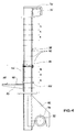
- the plywood pressing device 10 shown in Fig. 1 is used to manufacture sheet binders, d. H. of curved wood glue binders 12.
- Bow binders have an increased load capacity compared to straight binders due to their curved underside 14 and top 16.
- the device 10 has a substructure 18 with which it is supported on a floor 20.
- a vertical frame 22 is fastened to the substructure 18 (FIG. 3).
- This frame 22 has vertically aligned, spaced-apart straightening handles 24. These straightening handles 24 are in the horizontal direction, i. H. in the vertical direction out of the plane of the frame 22, slidably supported by means of the press cylinder 26 (Fig. 3).
- This frame 28 When the device 10 is closed, there is a second, front vertical frame 28 at a parallel distance from the rear vertical frame 22.
- This frame 28 also has vertically aligned, spaced-apart straightening handles 30.
- the straightening handles 30 are aligned so that they are offset from the straightening handles 24.
- the frame 28 is pivotally mounted about a pivot shaft 32 in the area of the substructure 18.
- the pivoting is made possible by means of a pressing device 29.
- the pivoting movement is represented in FIG. 3 by an arrow 34.
- the frame 28 can thus be pivoted from the vertical orientation shown in FIG. 1 into a horizontal orientation and thus by approximately 90 degrees.
- the straightening handles 30 of the front vertical frame 28 are connected in their upper region by a frame leg 36 running parallel to the pivot shaft 32.
- This frame leg 36 is attached to the outside of the directional handles 38.
- a rod-shaped stand 38 which is aligned parallel to the directional stems 30, is present in each case between two directional stems 30.
- This stand has at its upper end a claw 40 with which it grips around the inside of the frame leg 36 and can thus be supported on the frame leg 36 in the horizontal direction.
- the stand 38 has two base plates 42 which have an arch 44.
- the curvature 44 is adapted in size and curvature to the outside of the pivot shaft 32. As a result, the base plate 42 and thus also the stand 38 can sit snugly on the swivel shaft 32.
- the two base plates 42 and thus also the stand 38 in question can be displaced or shifted as desired in the longitudinal axis 33 of the pivot shaft 32.
- This arbitrary lateral displacement also allows the claw 40, so that each stand 38 can thereby be placed laterally offset on the swivel shaft 32 and the frame leg 36. This is indicated by way of example in FIG.
- each stand 38 In its longitudinal direction, ie perpendicular to the longitudinal axis 33 of the pivot shaft 32, each stand 38 has a series of bores 45, which are each arranged at a distance a from one another (FIGS. 2-4).
- a U-shaped holding plate 46 On the inside of the stand is a U-shaped holding plate 46 is present, on which an abutment plate 48 is attached, projecting inward.
- a stiffening plate 50 fastened under the abutment plate 48 serves for the rigid mounting of the abutment plate 48 on the holding plate 46.
- the abutment plate 48 forms a lower support for the stack 52 of laminated wood slats.
- the underside 14 of this laminated wood lamella stack 52 rests on the abutment plate 48 (FIG. 1).
- the holding plate 46 is screwed to the stand 38 by means of a screw 54 which passes through one of the bores 45.
- a bolt 56 is also fastened to the holding plate 46 and protrudes through another of the bores 45.
- the holding plate 46 is held against rotation on the stand 38 by means of the screw 54 and the bolt 56, which are spaced apart from one another.
- the high pressure forces 58 acting on the abutment plate 48 which occur during the pressing of the laminated wood lamella stack 52, can be absorbed by the stand 38 and derived into the pivot shaft 33 and the upper frame leg 36 and thus into the entire laminated wood pressing device 10.
- the laminated wood pressing device 10 also has an upper structure 60 which is fixedly connected to the vertical rear frame 22. Press cylinders 62 are fastened to this superstructure 60. These press cylinders 62 are connected in a manner not shown to a corresponding pressure medium source via a hydraulic pressure medium line. By introducing pressure medium into the press cylinder 62, each piston rod 64 of the press cylinder 62 in question can be moved out of the same or retracted in the opposite direction. A press plate 66 is attached to the lower end of each piston rod 64. The attachment is carried out by means of a pivot shaft 68, which is oriented perpendicular to the longitudinal direction of the press cylinder and perpendicular to the longitudinal orientation 67 of the plywood pressing device 10 is.
- the press plate 66 is pivotally attached to the piston rod 64.
- the press plate 66 can thus rest on the entire surface of the top 16 of the laminated wood lamella stack 52 as soon as the piston rod 64 has moved out of the press cylinder 62 accordingly.
- the production of a bent wood glue binder in the laminated wood pressing device 10 is carried out in the following way. Individual plywood slats 52.1-52.8 are pushed or placed on the frame frame 28 pivoted down into the horizontal.
- the abutment plates 48 are fastened to the stands 38 in accordance with the arch shape of the underside 14. If the corresponding stack 52 is already placed superimposed, the frame 28 is pivoted into its vertical position shown in FIG. 1.
- the stack 52 is laterally aligned and held between the alignment posts 24, 30 of the two frame frames 22, 28.
- the stands 38 are not required as a lateral holder. Because the stands 38 are at a certain distance from the stack 52, the stack 52 does not rest on the stands 38 when the frame 30 is opened.
- the stands 38 can thus be moved or precisely aligned in the longitudinal direction 67 during the stacking process.
- the press cylinders 62 are pressurized with pressure medium, so that their press plates 66 move to the top 16 of the stack 52. Since all press cylinders 62 are connected to a common pressure medium line, all press plates 66 finally press against the upper side 16 with the same force.
- the pressure plates 66 are moved back again, the front frame 30 is pivoted away from the rear frame 22 and the laminated wood lamella stack 52 is transported out of the device 10, for example by means of a crane. A new plywood slat stack 52 can then be assembled on the front frame 28 pivoted into the horizontal.
- the abutment plate 48 is fastened to the stand 38 in a rotationally fixed manner. As a result, the abutment plate 48 will press itself more or less strongly into the underside 14. Since the bottom lamella 52.1 is not regularly part of the wood glue binder, these press-in does not interfere. However, these press-ins can be avoided or at least greatly reduced if the abutment plate 48 is fastened to the stand 38 so as to be pivotable about a pivot shaft parallel to the pivot shaft 68 of the press plate 66. Similar to the press plate 66 can then also Align the abutment plate 48 parallel to the arch shape of the stack 52, ie to the underside 14. The pressure forces 58 acting on the abutment plate 48 can then be distributed over the entire surface of the abutment plate 48 on the underside 14 of the stack 52.
Landscapes
- Engineering & Computer Science (AREA)
- Life Sciences & Earth Sciences (AREA)
- Manufacturing & Machinery (AREA)
- Wood Science & Technology (AREA)
- Forests & Forestry (AREA)
- Mechanical Engineering (AREA)
- Veneer Processing And Manufacture Of Plywood (AREA)
Applications Claiming Priority (2)
| Application Number | Priority Date | Filing Date | Title |
|---|---|---|---|
| DE4119009 | 1991-06-08 | ||
| DE4119009A DE4119009A1 (de) | 1991-06-08 | 1991-06-08 | Schichtholzpressvorrichtung zum herstellen von gebogenen holzleimbindern |
Publications (2)
| Publication Number | Publication Date |
|---|---|
| EP0518217A1 true EP0518217A1 (fr) | 1992-12-16 |
| EP0518217B1 EP0518217B1 (fr) | 1995-08-23 |
Family
ID=6433580
Family Applications (1)
| Application Number | Title | Priority Date | Filing Date |
|---|---|---|---|
| EP92109471A Expired - Lifetime EP0518217B1 (fr) | 1991-06-08 | 1992-06-04 | Presse pour bois à lames pour la fabrication de poutres fermes collées et arguées |
Country Status (3)
| Country | Link |
|---|---|
| EP (1) | EP0518217B1 (fr) |
| AT (1) | ATE126750T1 (fr) |
| DE (2) | DE4119009A1 (fr) |
Cited By (8)
| Publication number | Priority date | Publication date | Assignee | Title |
|---|---|---|---|---|
| EP0624441A1 (fr) * | 1993-05-11 | 1994-11-17 | REINHOLD HESS GmbH & Co. KG. MASCHINENBAU | Presse à cadre |
| WO1996027056A1 (fr) * | 1995-02-28 | 1996-09-06 | Hausbau Schöb Ag | Elements de construction en bois et leur systeme d'assemblage |
| US5727457A (en) * | 1995-10-05 | 1998-03-17 | Prensas Ramarch, S.L. | Hydraulic press for forming door frames and panels or the like |
| ITUD20100219A1 (it) * | 2010-11-29 | 2012-05-30 | Gianfranco Ventre | Macchina e procedimento per la sagomatura di una trave in materiale legnoso |
| CN110328730A (zh) * | 2019-07-31 | 2019-10-15 | 烟台博海木工机械有限公司 | 一种木梁压机 |
| CN112589929A (zh) * | 2020-12-11 | 2021-04-02 | 黄祥梅 | 一种胶合板热压工艺中的板胚定位工装 |
| CN117301233A (zh) * | 2023-11-09 | 2023-12-29 | 江苏零界科技集团有限公司 | 胶合木弯梁自动加压生产设备 |
| CN117507086A (zh) * | 2023-10-20 | 2024-02-06 | 中建科技集团华南有限公司 | 一种木拱梁的胶合设备和方法 |
Families Citing this family (3)
| Publication number | Priority date | Publication date | Assignee | Title |
|---|---|---|---|---|
| DE202012011616U1 (de) * | 2012-12-05 | 2013-12-06 | H.I.T. Maschinenbau Gmbh + Co. Kg | Presse für Leimbinder |
| DE102013001100B4 (de) * | 2013-01-23 | 2020-07-30 | Minda Industrieanlagen Gmbh | Vorrichtung und Verfahren zum Herstellen von Holzleimbindern |
| CN114030040A (zh) * | 2021-12-09 | 2022-02-11 | 湖南红崀山木业科技有限公司 | 一种胶合板多层一次性加工设备 |
Citations (3)
| Publication number | Priority date | Publication date | Assignee | Title |
|---|---|---|---|---|
| US4141775A (en) * | 1977-08-12 | 1979-02-27 | Bohemia, Inc. | Hydraulic board-laminating press |
| EP0211810A1 (fr) * | 1985-06-10 | 1987-02-25 | Remo Angelucci | Plateau de formage de structures laminées courbes |
| US4776919A (en) * | 1986-01-24 | 1988-10-11 | Trus Joist Corporation | Laminated lumber press apparatus |
-
1991
- 1991-06-08 DE DE4119009A patent/DE4119009A1/de not_active Withdrawn
-
1992
- 1992-06-04 EP EP92109471A patent/EP0518217B1/fr not_active Expired - Lifetime
- 1992-06-04 AT AT92109471T patent/ATE126750T1/de not_active IP Right Cessation
- 1992-06-04 DE DE59203346T patent/DE59203346D1/de not_active Expired - Fee Related
Patent Citations (3)
| Publication number | Priority date | Publication date | Assignee | Title |
|---|---|---|---|---|
| US4141775A (en) * | 1977-08-12 | 1979-02-27 | Bohemia, Inc. | Hydraulic board-laminating press |
| EP0211810A1 (fr) * | 1985-06-10 | 1987-02-25 | Remo Angelucci | Plateau de formage de structures laminées courbes |
| US4776919A (en) * | 1986-01-24 | 1988-10-11 | Trus Joist Corporation | Laminated lumber press apparatus |
Cited By (9)
| Publication number | Priority date | Publication date | Assignee | Title |
|---|---|---|---|---|
| EP0624441A1 (fr) * | 1993-05-11 | 1994-11-17 | REINHOLD HESS GmbH & Co. KG. MASCHINENBAU | Presse à cadre |
| WO1996027056A1 (fr) * | 1995-02-28 | 1996-09-06 | Hausbau Schöb Ag | Elements de construction en bois et leur systeme d'assemblage |
| US5727457A (en) * | 1995-10-05 | 1998-03-17 | Prensas Ramarch, S.L. | Hydraulic press for forming door frames and panels or the like |
| ITUD20100219A1 (it) * | 2010-11-29 | 2012-05-30 | Gianfranco Ventre | Macchina e procedimento per la sagomatura di una trave in materiale legnoso |
| CN110328730A (zh) * | 2019-07-31 | 2019-10-15 | 烟台博海木工机械有限公司 | 一种木梁压机 |
| CN110328730B (zh) * | 2019-07-31 | 2023-12-29 | 烟台博海木工机械有限公司 | 一种木梁压机 |
| CN112589929A (zh) * | 2020-12-11 | 2021-04-02 | 黄祥梅 | 一种胶合板热压工艺中的板胚定位工装 |
| CN117507086A (zh) * | 2023-10-20 | 2024-02-06 | 中建科技集团华南有限公司 | 一种木拱梁的胶合设备和方法 |
| CN117301233A (zh) * | 2023-11-09 | 2023-12-29 | 江苏零界科技集团有限公司 | 胶合木弯梁自动加压生产设备 |
Also Published As
| Publication number | Publication date |
|---|---|
| DE4119009A1 (de) | 1992-12-10 |
| DE59203346D1 (de) | 1995-09-28 |
| ATE126750T1 (de) | 1995-09-15 |
| EP0518217B1 (fr) | 1995-08-23 |
Similar Documents
| Publication | Publication Date | Title |
|---|---|---|
| EP0518217B1 (fr) | Presse pour bois à lames pour la fabrication de poutres fermes collées et arguées | |
| DE1752098A1 (de) | Presse mit einem aus dieser herausfuehrbaren Rollentraeger od.dgl. | |
| DE102012102208B4 (de) | Automatische Presse zum Querleimen massiver lamellenartiger Elemente | |
| DE102009019458B4 (de) | Pressenanlage | |
| DE2801904A1 (de) | Geraet zum herstellen von holzkonstruktionen | |
| DE29617447U1 (de) | Bohrtisch | |
| DE3120897A1 (de) | "presse zum herstellen von holmen oder platten aus verleimten staeben" | |
| DE3027873A1 (de) | Vorrichtung zum zusammennageln von aus mehreren bretterschichten bestehenden schalungsplatten | |
| DE3808754C2 (de) | Verfahren zum Einbringen von Preßpfählen und Spunddielen | |
| DE2512185C2 (de) | Vorrichtung zum stirnseitigen Verleimen von Platten | |
| DE102013001100B4 (de) | Vorrichtung und Verfahren zum Herstellen von Holzleimbindern | |
| EP1125700A1 (fr) | Procédé de fabrication de lamellés collés incurvés | |
| AT404332B (de) | Lamellierpresse | |
| DE4127053C2 (de) | Plattenpresse | |
| DE19622324C2 (de) | Montagepresse für die Herstellung von Holzfertigbauelementen | |
| DE20103899U1 (de) | Pressvorrichtung | |
| DE2624003A1 (de) | Anlage bzw. vorrichtung zur herstellung von traegern aus geleimten lamellen | |
| DE9320608U1 (de) | Vorrichtung zur Verlegung eines Fertigparkett- oder Laminarfußbodens | |
| DE4315606C1 (de) | Rahmenpresse | |
| DE2414139C3 (de) | Anlage zum Herstellen von Holzträgern | |
| DE2502373C3 (de) | Verfahren zum Herstellen von Bauelementen, bestehend aus Ober- und Unterplatten aus nagelfähigem Werkstoff und Vorrichtung zum Durchführen des Verfahrens | |
| EP0183675A2 (fr) | Dispositif pour assembler des poutres latéralement en utilisant des connecteurs | |
| DE3344460A1 (de) | Steinstapelgreifer | |
| DE4041553A1 (de) | Verfahren und einrichtung zum kontinuierlichen pressverleimen von leisten | |
| DE2302912A1 (de) | Verfahren und vorrichtung zum zusammenpressen von auf einer foerdereinrichtung liegenden guetern |
Legal Events
| Date | Code | Title | Description |
|---|---|---|---|
| PUAI | Public reference made under article 153(3) epc to a published international application that has entered the european phase |
Free format text: ORIGINAL CODE: 0009012 |
|
| AK | Designated contracting states |
Kind code of ref document: A1 Designated state(s): AT BE CH DE DK FR IT LI LU NL SE |
|
| 17P | Request for examination filed |
Effective date: 19930426 |
|
| 17Q | First examination report despatched |
Effective date: 19940518 |
|
| GRAA | (expected) grant |
Free format text: ORIGINAL CODE: 0009210 |
|
| AK | Designated contracting states |
Kind code of ref document: B1 Designated state(s): AT BE CH DE DK FR IT LI LU NL SE |
|
| PG25 | Lapsed in a contracting state [announced via postgrant information from national office to epo] |
Ref country code: IT Free format text: LAPSE BECAUSE OF FAILURE TO SUBMIT A TRANSLATION OF THE DESCRIPTION OR TO PAY THE FEE WITHIN THE PRESCRIBED TIME-LIMIT;WARNING: LAPSES OF ITALIAN PATENTS WITH EFFECTIVE DATE BEFORE 2007 MAY HAVE OCCURRED AT ANY TIME BEFORE 2007. THE CORRECT EFFECTIVE DATE MAY BE DIFFERENT FROM THE ONE RECORDED. Effective date: 19950823 Ref country code: FR Free format text: THE PATENT HAS BEEN ANNULLED BY A DECISION OF A NATIONAL AUTHORITY Effective date: 19950823 Ref country code: BE Effective date: 19950823 Ref country code: NL Free format text: LAPSE BECAUSE OF FAILURE TO SUBMIT A TRANSLATION OF THE DESCRIPTION OR TO PAY THE FEE WITHIN THE PRESCRIBED TIME-LIMIT Effective date: 19950823 Ref country code: DK Effective date: 19950823 |
|
| REF | Corresponds to: |
Ref document number: 126750 Country of ref document: AT Date of ref document: 19950915 Kind code of ref document: T |
|
| REF | Corresponds to: |
Ref document number: 59203346 Country of ref document: DE Date of ref document: 19950928 |
|
| PG25 | Lapsed in a contracting state [announced via postgrant information from national office to epo] |
Ref country code: SE Effective date: 19951123 |
|
| EN | Fr: translation not filed | ||
| NLV1 | Nl: lapsed or annulled due to failure to fulfill the requirements of art. 29p and 29m of the patents act | ||
| PG25 | Lapsed in a contracting state [announced via postgrant information from national office to epo] |
Ref country code: AT Effective date: 19960604 |
|
| PLBE | No opposition filed within time limit |
Free format text: ORIGINAL CODE: 0009261 |
|
| STAA | Information on the status of an ep patent application or granted ep patent |
Free format text: STATUS: NO OPPOSITION FILED WITHIN TIME LIMIT |
|
| PG25 | Lapsed in a contracting state [announced via postgrant information from national office to epo] |
Ref country code: LU Free format text: LAPSE BECAUSE OF NON-PAYMENT OF DUE FEES Effective date: 19960630 |
|
| 26N | No opposition filed | ||
| PGFP | Annual fee paid to national office [announced via postgrant information from national office to epo] |
Ref country code: CH Payment date: 20010622 Year of fee payment: 10 |
|
| PG25 | Lapsed in a contracting state [announced via postgrant information from national office to epo] |
Ref country code: LI Free format text: LAPSE BECAUSE OF NON-PAYMENT OF DUE FEES Effective date: 20020630 Ref country code: CH Free format text: LAPSE BECAUSE OF NON-PAYMENT OF DUE FEES Effective date: 20020630 |
|
| REG | Reference to a national code |
Ref country code: CH Ref legal event code: PL |
|
| PGFP | Annual fee paid to national office [announced via postgrant information from national office to epo] |
Ref country code: DE Payment date: 20040621 Year of fee payment: 13 |
|
| PG25 | Lapsed in a contracting state [announced via postgrant information from national office to epo] |
Ref country code: DE Free format text: LAPSE BECAUSE OF NON-PAYMENT OF DUE FEES Effective date: 20060103 |