EP0518698A2 - Panneau de surpression - Google Patents
Panneau de surpression Download PDFInfo
- Publication number
- EP0518698A2 EP0518698A2 EP92305438A EP92305438A EP0518698A2 EP 0518698 A2 EP0518698 A2 EP 0518698A2 EP 92305438 A EP92305438 A EP 92305438A EP 92305438 A EP92305438 A EP 92305438A EP 0518698 A2 EP0518698 A2 EP 0518698A2
- Authority
- EP
- European Patent Office
- Prior art keywords
- panel
- assembly
- open
- stop member
- frame
- Prior art date
- Legal status (The legal status is an assumption and is not a legal conclusion. Google has not performed a legal analysis and makes no representation as to the accuracy of the status listed.)
- Granted
Links
Images



Classifications
-
- E—FIXED CONSTRUCTIONS
- E06—DOORS, WINDOWS, SHUTTERS, OR ROLLER BLINDS IN GENERAL; LADDERS
- E06B—FIXED OR MOVABLE CLOSURES FOR OPENINGS IN BUILDINGS, VEHICLES, FENCES OR LIKE ENCLOSURES IN GENERAL, e.g. DOORS, WINDOWS, BLINDS, GATES
- E06B5/00—Doors, windows, or like closures for special purposes; Border constructions therefor
- E06B5/10—Doors, windows, or like closures for special purposes; Border constructions therefor for protection against air-raid or other war-like action; for other protective purposes
- E06B5/12—Doors, windows, or like closures for special purposes; Border constructions therefor for protection against air-raid or other war-like action; for other protective purposes against air pressure, explosion, or gas
- E06B5/125—Closures for relieving excess pressure inside the building
-
- E—FIXED CONSTRUCTIONS
- E04—BUILDING
- E04B—GENERAL BUILDING CONSTRUCTIONS; WALLS, e.g. PARTITIONS; ROOFS; FLOORS; CEILINGS; INSULATION OR OTHER PROTECTION OF BUILDINGS
- E04B1/00—Constructions in general; Structures which are not restricted either to walls, e.g. partitions, or floors or ceilings or roofs
- E04B1/62—Insulation or other protection; Elements or use of specified material therefor
- E04B1/92—Protection against other undesired influences or dangers
- E04B1/98—Protection against other undesired influences or dangers against vibrations or shocks; against mechanical destruction, e.g. by air-raids
-
- E—FIXED CONSTRUCTIONS
- E06—DOORS, WINDOWS, SHUTTERS, OR ROLLER BLINDS IN GENERAL; LADDERS
- E06B—FIXED OR MOVABLE CLOSURES FOR OPENINGS IN BUILDINGS, VEHICLES, FENCES OR LIKE ENCLOSURES IN GENERAL, e.g. DOORS, WINDOWS, BLINDS, GATES
- E06B5/00—Doors, windows, or like closures for special purposes; Border constructions therefor
- E06B5/10—Doors, windows, or like closures for special purposes; Border constructions therefor for protection against air-raid or other war-like action; for other protective purposes
- E06B5/12—Doors, windows, or like closures for special purposes; Border constructions therefor for protection against air-raid or other war-like action; for other protective purposes against air pressure, explosion, or gas
Definitions
- This invention relates to pressure relief or "blow-out" panels and the like, intended for use in buildings in which there is a risk of explosion.
- Blow-out panels have in the past been retained by mechanical devices such as shear bolts which are designed to break under a predetermined load and allow the panel to blow-out.
- shear bolts which are designed to break under a predetermined load and allow the panel to blow-out.
- this type of system it has been difficult to adjust accurately the pressure at which a particular panel will blow-out.
- the pressure at which blow-out will occur tends to change.
- part or all of the panel or at least the shear bolts are destroyed and must be replaced.
- Canadian patent 1,241,517 issued September 6, 1988 and entitled "PRESSURE RELIEF PANELS AND LOUVERS" discloses a pressure relief panel arrangement in which a calibrated magnet and striker set is used to hold the panel closed.
- the magnet has a maximum holding force substantially exceeding the known force to which it is subjected at the predetermined blow-open pressure, and at least one non-magnetic shim is used of thickness selected to reduce the magnet holding force to the known force.
- the disclosure of patent 1,241,517 is hereby incorporated by reference into this application.
- a pressure relief panel assembly for protecting a building against over-pressure and comprising a displaceable, pressure relief, panel, and panel release means for holding the panel normally in a closed position and able to release the panel for displacement to an open position when the panel is subjected to a predetermined blow-open pressure, characterised in that there is a hold-open mechanism, for holding said panel at least partly open after it has been moved from the closed position, thus to reduce the likelihood of damage owing to implosion.
- a pressure relief panel assembly for protecting a building against over-pressure
- said assembly including a frame, a panel pivotally coupled to the frame for movement between a normal closed position and an opened position, and panel release means normally holding said panel in closed position but adapted to release when the panel is subjected to a predetermined blow-open pressure
- the improvement comprising a hold-open mechanism for holding said panel at least partly open after it has been opened by over-pressure in said building, said hold-open mechanism comprising means coupled to one of said panel and said frame and responsive to the opening of said panel to at least a predetermined extend for thereupon holding said panel at least partly open, whereby to reduce the likelihood of implosion in said building.
- the invention provides a method of protecting a building against over-pressures in said building, said method comprising providing a panel pivoted to said building at a pivot axis for said panel to blow open about said pivot axis upon the occurrence of an over-pressure in said building, and holding said panel at least partly open after said panel has blown open, thereby to reduce the likelihood of damage due to implosion in said building.
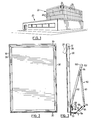
- FIG. 1 shows a building 20 having a section 22, for example a laboratory section, in which there is a risk of explosion.
- the walls of section 22 include arrays 24 of pressure relief or blow-out wall panel assemblies 26.
- the panel assembly 26 includes a panel member 28 surrounded by a frame 30.
- the frame 30 is connected to the building structure by clips or brackets (not shown) and effectively forms part of the building structure.
- the panel member 28 is pivotally connected to the frame 30 by a pivot shaft 32.
- Pivot shaft 32 extends through the panel member 28 and outwardly through the side members of the frame 30.
- the shaft 32 is typically held stationary with respect to the panel by a set screw (not shown) and is journalled in suitable bushings (not shown) in the sides of the frame 30.
- the panel member 28 is normally held closed by a magnet 36 (Fig. 4) carried by a support bracket 38 connected to the frame 30. Bolts 39 hold the magnet in position.
- the magnet 36 cooperates with a striker plate 40 connected to the back of the panel member 28 by bracket 42. Bracket 42 is screwed and/or glued to the back of panel member 28.
- One or more non-magnetic shims are placed on the top surface of the striker plate 40 to calibrate the holding force between the magnet and striker plate.
- the magnet is of greater force than required, and the magnetic holding force is reduced by the shims 44 to a desired known force so that the panel will blow open at a predetermined over-pressure in the building being protected.
- the extent to which the panel member 28 can open is controlled by a linkage indicated at 50 in Figs. 3 and 4.
- the linkage 50 includes an angled flat plate bracket 52 bolted at 53 to channel 54 which is secured to the building structure; an intermediate channel 56 bolted at 58 to the bracket 52, and a pair of arms 60, 62.
- the arms 60, 62 are each of U-channel configuration.
- the first arm 60 is pivotally connected at 64 to the intermediate channel 56, and the second arm 62 is pivotally connected at 66 to the first arm 60.
- the second arm 62 is also pivotally connected at 68 to a mount 70.
- the mount 70 is bolted at 72 to the bracket 42 attached to the rear of panel member 28.
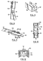
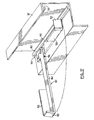
- Stop member 80 shown in Figs. 4 and 5 is provided.
- Stop member 80 is formed of a U-channel section (Fig. 5) with an angled front face 82 and pivot holes 84. Stop member 80 is pivotally connected (through holes 84, Fig. 5) to the mount 70 (which as mentioned is in turn fastened to bracket 42 by bolts 72).
- the lower surface of stop member 80 normally rests on the upper edge of bracket 42, as shown in Fig. 4.
- a spring 86 (Fig. 6) biases stop member 80 downwardly, to prevent stop member 80 from flipping up.
- Spring 86 is generally U-shaped, having a lower leg 88, a vertical wall 90, and a downwardly sloping upper leg 92 which overlies the web 94 of stop member 80.
- Lower leg 88 is secured by being held between mount 70 and the upper flange of bracket 42.
- the stop member 80 pivots downwardly slightly. Then, as the panel member 28 begins to close, the face 82 of stop member 80 moves against the front face 96 of the magnet 36 (Fig. 7), preventing the panel member 28 from fully closing.
- the face 82 which is angled at about 60 degrees to the axis of member 80, rests substantially flush with the magnet face.
- the spring 86 allows some resilience but prevents stop member 80 from flipping up.
- the panel member 28 is opened slightly and the stop member 80 is pivoted upwardly (against spring 86) to clear the magnet 36 and magnet support bracket 38.
- the panel member 28 then can be re-closed, after which stop member 80 again assumes the position shown in Fig. 4.
- the stop member 80 will be between six and eight inches long, but its length can be adjusted as required, depending on the extent to which it is desired to hold panel member 28 open after it has blown open.
- the extent to which the panel member 28 must be held open will depend on factors such as the size and number of the panels, and the volume of the space being protected, but typically the bottom inner edge 28a (Fig. 7) of the panel should be held between two and ten inches away from the bottom outer edge 30a of the inside perimeter of the frame.
- a preferred distance is four to five inches. This is much less than the amount which the panel opens, but it is found generally sufficient.
- arms 60, 62 have been shown as operating in a vertical plane, they can instead be arranged to operate in a horizontal plane, if desired.
- arms 60, 62 can instead be arranged to operate in a horizontal plane, if desired.
- they are shown as made from U-shaped stock, other structural shapes can be used.
- Figs. 8 to 10 show a different arrangement for holding the panel member 28 open after it has blown open. It will be seen that as shown in Fig. 3, the second arm 62 extends beyond the pivot connection 66 as an arm extension 100. Arm extension 100 carries a U-shaped spring 102, which is shown in dotted lines in Fig. 3 since it is an alternative to stop member 80.
- Spring 102 is shown in detail in Fig. 9. As shown, spring 102 has a base 104, upstanding legs 106, and inturned edges or “barbs" 108 at the tops of legs 106.
- the base 104 is mounted on arm extension 100 by bolts 110 and wing nuts 112, as shown in Figs. 8, 10 and 12, with the spring 102 inside the channel of extension 100.
- the barbs 108 face away from arm extension 100, in a direction to receive arm 60 when the arms pivot into a straight line as the panel member 28 blows out.
- the wing nuts 112 are removed, detaching the spring 102 from the second arm 62.
- the spring 102 can then be conveniently removed from the first arm 60 and re-attached by the wing nuts to the second arm 62.
- the spring 102 may be held to arm 62 by two rivets (not shown), in which case detachment occurs simply by using locking pliers to snap the barbs 108 of the spring 102 away from arm 62.
- stop member 80 can be used with the spring 102, as a backup to the spring.
- any other desired catch system can be used to catch the arms 60, 62 and hold them straight once they have moved to a straight configuration.
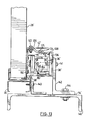
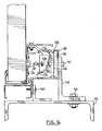
- Figs. 13 to 16 show another embodiment of the invention.
- primed reference numerals indicate parts corresponding to those of Figs. 1 to 12.
- the Figs. 13 to 16 embodiment deal with the problem that in the Figs. 1 to 12 embodiment, the shock absorber bracket 52, the linkage 50 and the stop member 80 project into the interior of the building when the panel member 28 is closed. Sometimes the space that they occupy is needed for other purposes.
- the linkage 50 has been eliminated and its function as a panel restraint device, holding the panel from blowing out too far, is performed by a cable restraint arrangement.
- the cable restraint arrangement includes a cable restraint bracket 120 secured to bracket 42′ by bolt 122.
- a cable 124 passes through a hole 126 in the end of bracket 120 and, as shown in Figs. 14 and 15, passes through a hole 128 in the bent end 130 of a shock absorber bracket 132.
- the shock absorber bracket 132 is bolted by bolts 134 to a strong metal (e.g. steel or heavy aluminum) backing bar 136.
- Backing bar 136 is fitted into a channel 138 in support bracket 38′.
- Bracket 38′ is as before secured to the frame 30 (by bolt 140). However in addition, and as best shown in Fig. 14, bolts 141 extend through a strong metal angle 142 (e.g. steel, or heavy aluminum) which is secured by bolts 144 to a steel structural channel 146 which is firmly secured to the building.
- a strong metal angle 142 e.g. steel, or heavy aluminum
- the backing bar 136 and its connection through angle 142 to channel 146 are provided because when the panel is blown open, very large loads are generated when the panel is stopped.
- the load which is imposed on the shock absorber bracket 132 when the panel is stopped is now transferred to the backing bar 136, and then through angle 142 to channel 146 of the building, so that the thinner aluminum components of the frame are not exposed to high forces when the panel is blown open.
- the bent end 130 of the shock absorber bracket 132 will bend if necessary, to absorb excess loads, and also, since it is bent away from backing bar 136, it provides space between shock absorber bracket 132 and the backing bar 136 to allow the cable 124 to be tied around the shock absorber bracket.
- the backing bar 136 also serves as a mount for the magnet 36′, as best shown in Figs. 13 and 16.
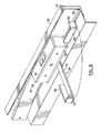
- stop member 80′ is best shown in Figs. 13, 16 and 17.
- stop member 80′ includes a flat bar 150 having an upwardly bent end 152.
- Bar 150 is secured to bracket 38′ by a rivet 154 which extends through bracket 38′.
- One leg of a coil spring 156 extends over an edge of arm 150 and biases bar 152 to an extended position shown in full lines in Figs. 16 and 17.
- stop member 80′ is normally retained in a retracted position shown in dotted lines in Figs. 16 and 17 (and also shown in Fig. 13) when the panel member 28 is closed.
- a bent up side 158 of bar 150 is flush (Fig. 16) with the face 160 of the magnet 36′ and contacts a portion of the striker plate 40 (not shown in Figs. 16 and 17), thereby holding the stop member 80′ in its retracted position.
- the spring 156 (which need not be particularly powerful) biases the stop member 80′ outwardly to the full line position shown in Figs. 16 and 17. In its extended position, which is at right angles to its retracted position, stop member 80′ extends toward the panel 28′. Stop member 80′ is prevented from pivoting too far by engagement of its rear edge 162 (Fig. 17) with extruded edge 164 of bracket 38′.
- While the cable 124 is shown as fastened to the centre of the panel, it can if desired be fastened off centre, or two cables can be used with separate shock absorbing brackets, one attached near each corner of the blow-open panel.
- backing bar 136 is preferred, it can be eliminated. In that case magnet 36′ would be bolted directly to channel 38′, and the shock absorber bracket 132 would be bolted directly through bracket 38′ to angle 142.
- stop member 80′ is shown connected to frame bracket 38′, it could alternatively be connected to a bracket mounted on the panel and would then pivot toward the frame when the panel opens.
- stop member 80′ is mounted in the middle of the channel for manufacturing convenience, it can be mounted off centre.
- two stop members can be used, one at each end of the panel, and attached either to the panel or to the frame.
- the stop member 80′ rather than being pivoted, can be fastened directly to the panel or frame with a flat U-shaped spring so that when the panel is released, the spring will move stop member 80′ into the path of another component and block the panel from closing, thereby reducing the vacuum effect in the building after an over pressure condition.
- the hold open device can be made of resilient material such as rubber, having its normal shape deformed during the closing process. Then, when the panel is blown open, the hold open devices will assume their normal shape and interpose themselves between two components, preventing the panel from closing. However care should be taken to hold the panel far enough open that implosion forces will be sufficiently relieved.
Landscapes
- Engineering & Computer Science (AREA)
- Structural Engineering (AREA)
- Architecture (AREA)
- Civil Engineering (AREA)
- Environmental & Geological Engineering (AREA)
- Physics & Mathematics (AREA)
- Electromagnetism (AREA)
- Building Environments (AREA)
- Diaphragms For Electromechanical Transducers (AREA)
- Amplifiers (AREA)
- Lubrication Of Internal Combustion Engines (AREA)
- Treating Waste Gases (AREA)
- Glass Compositions (AREA)
- Conveying And Assembling Of Building Elements In Situ (AREA)
- Buildings Adapted To Withstand Abnormal External Influences (AREA)
- Structure Of Emergency Protection For Nuclear Reactors (AREA)
Applications Claiming Priority (2)
| Application Number | Priority Date | Filing Date | Title |
|---|---|---|---|
| CA2044489 | 1991-06-13 | ||
| CA002044489A CA2044489C (fr) | 1991-06-13 | 1991-06-13 | Appareil et methode de retenue de panneau limiteur de pression |
Publications (3)
| Publication Number | Publication Date |
|---|---|
| EP0518698A2 true EP0518698A2 (fr) | 1992-12-16 |
| EP0518698A3 EP0518698A3 (en) | 1993-04-07 |
| EP0518698B1 EP0518698B1 (fr) | 1998-09-16 |
Family
ID=4147807
Family Applications (1)
| Application Number | Title | Priority Date | Filing Date |
|---|---|---|---|
| EP92305438A Expired - Lifetime EP0518698B1 (fr) | 1991-06-13 | 1992-06-12 | Panneau de surpression |
Country Status (5)
| Country | Link |
|---|---|
| US (2) | US5271189A (fr) |
| EP (1) | EP0518698B1 (fr) |
| AT (1) | ATE171237T1 (fr) |
| CA (1) | CA2044489C (fr) |
| DE (1) | DE69226988T2 (fr) |
Cited By (7)
| Publication number | Priority date | Publication date | Assignee | Title |
|---|---|---|---|---|
| GB2278376A (en) * | 1993-05-28 | 1994-11-30 | Abb Miljoe Norsk Viftefab | Pressure relief device for roof or wall |
| GB2294276A (en) * | 1994-10-12 | 1996-04-24 | Shell Int Research | Explosion relief wall |
| WO1998057025A1 (fr) * | 1997-06-12 | 1998-12-17 | Anglin Richard L Jr | Systeme reduisant la formation d'eclats |
| EP1580392A3 (fr) * | 2004-03-22 | 2007-03-07 | Colt International Holdings Ag | Fermeture pour une ouverture d'un bâtiment |
| EP2669443A1 (fr) | 2012-05-31 | 2013-12-04 | Holding Dinnissen B.V. | Dispositif de libération de pression |
| RU177097U1 (ru) * | 2017-10-05 | 2018-02-08 | Александр Федорович Миронов | Легкосбрасываемая ограждающая строительная конструкция для взрывоопасных помещений |
| CN109989654A (zh) * | 2017-12-30 | 2019-07-09 | 中国人民解放军63653部队 | 钢丝绳自对心盘型门闭合方法 |
Families Citing this family (16)
| Publication number | Priority date | Publication date | Assignee | Title |
|---|---|---|---|---|
| CA2044489C (fr) * | 1991-06-13 | 2006-03-21 | William Vincent | Appareil et methode de retenue de panneau limiteur de pression |
| US5461831A (en) * | 1993-12-29 | 1995-10-31 | Eastman Kodak Company | Assemblage and method for relieving overpressure in an enclosure |
| US5864989A (en) * | 1995-12-28 | 1999-02-02 | Kabushiki Kaisha Nihon Sekkei | Ventilating window |
| US6223473B1 (en) * | 1999-09-10 | 2001-05-01 | Cid Associates, Inc. | Explosion relief system including an explosion relief panel and a blast shaft having two openings |
| US7007892B2 (en) * | 2004-03-23 | 2006-03-07 | The Boeing Company | Insulating baffle for a floor shear truss |
| DE102004055111A1 (de) * | 2004-10-08 | 2006-06-14 | Sälzer Sicherheitstechnik GmbH | Rahmen-Glas-Verbund |
| US20070271845A1 (en) * | 2006-05-26 | 2007-11-29 | Wen Ming Chang | Explosion-venting door structure |
| NO332916B1 (no) * | 2010-01-08 | 2013-02-04 | Ikm Dsc Engineering As | Panel for offshore installasjoner |
| GB2514783A (en) * | 2013-06-03 | 2014-12-10 | Matthew Molloy | Over pressure venting system |
| CN103550894B (zh) * | 2013-11-08 | 2019-01-22 | 西安新竹防灾救生设备有限公司 | 机械式泄压装置 |
| US10260229B2 (en) * | 2017-04-12 | 2019-04-16 | Southern Comfort Shelters, Inc. | Blast resistant shelter and method of assembly |
| CN108951978B (zh) * | 2018-09-18 | 2019-11-22 | 东阳市智林科技有限公司 | 一种全隐框玻璃幕墙和拆卸工具及拆卸方法 |
| RU195434U1 (ru) * | 2019-11-20 | 2020-01-28 | Максим Александрович Ефремов | Узел крепления легкосбрасываемой конструкции |
| RU199687U1 (ru) * | 2020-03-26 | 2020-09-14 | Олег Александрович Петров | Разрушаемый элемент легкосбрасываемой оконной конструкции |
| RU207760U1 (ru) * | 2021-03-22 | 2021-11-15 | Максим Александрович Ефремов | Узел крепления легкосбрасываемой конструкции |
| RU208703U1 (ru) * | 2021-11-09 | 2021-12-30 | Виталий Геннадьевич Ружинский | Узел крепления легкосбрасываемой ограждающей строительной конструкции |
Family Cites Families (8)
| Publication number | Priority date | Publication date | Assignee | Title |
|---|---|---|---|---|
| US1887484A (en) * | 1929-09-21 | 1932-11-08 | David Luptons Sons Co | Explosion-release mechanism for windows |
| US2621377A (en) * | 1950-03-22 | 1952-12-16 | Julius J Ohlis | Explosion-type mounting for windows |
| US3453777A (en) * | 1967-11-07 | 1969-07-08 | American Cyanamid Co | Pressure venting panel assembly |
| GB1511489A (en) * | 1976-03-17 | 1978-05-17 | Colt Int Ltd | Ventilators ventilators |
| FR2542360B1 (fr) * | 1983-03-11 | 1987-10-09 | Alcaud Sa | Dispositif de trappe mobile notamment pour le desenfumage |
| CA1241517A (fr) * | 1987-03-18 | 1988-09-06 | Kenneth H. Betts | Panneaux et lucarnes de protection contre les ruptures explosives |
| NO165208C (no) * | 1989-02-09 | 1991-01-09 | Norsk Viftefabrikk As | Trykkavlastningspanel. |
| CA2044489C (fr) * | 1991-06-13 | 2006-03-21 | William Vincent | Appareil et methode de retenue de panneau limiteur de pression |
-
1991
- 1991-06-13 CA CA002044489A patent/CA2044489C/fr not_active Expired - Lifetime
-
1992
- 1992-06-08 US US07/895,073 patent/US5271189A/en not_active Expired - Lifetime
- 1992-06-12 DE DE69226988T patent/DE69226988T2/de not_active Expired - Lifetime
- 1992-06-12 AT AT92305438T patent/ATE171237T1/de not_active IP Right Cessation
- 1992-06-12 EP EP92305438A patent/EP0518698B1/fr not_active Expired - Lifetime
-
1993
- 1993-10-25 US US08/140,919 patent/US5417014A/en not_active Expired - Lifetime
Cited By (9)
| Publication number | Priority date | Publication date | Assignee | Title |
|---|---|---|---|---|
| GB2278376A (en) * | 1993-05-28 | 1994-11-30 | Abb Miljoe Norsk Viftefab | Pressure relief device for roof or wall |
| GB2278376B (en) * | 1993-05-28 | 1996-05-08 | Abb Miljoe Norsk Viftefab | Pressure release device |
| GB2294276A (en) * | 1994-10-12 | 1996-04-24 | Shell Int Research | Explosion relief wall |
| WO1998057025A1 (fr) * | 1997-06-12 | 1998-12-17 | Anglin Richard L Jr | Systeme reduisant la formation d'eclats |
| US6010758A (en) * | 1997-06-12 | 2000-01-04 | Anglin, Jr.; Richard L. | Shrapnel mitigation system |
| EP1580392A3 (fr) * | 2004-03-22 | 2007-03-07 | Colt International Holdings Ag | Fermeture pour une ouverture d'un bâtiment |
| EP2669443A1 (fr) | 2012-05-31 | 2013-12-04 | Holding Dinnissen B.V. | Dispositif de libération de pression |
| RU177097U1 (ru) * | 2017-10-05 | 2018-02-08 | Александр Федорович Миронов | Легкосбрасываемая ограждающая строительная конструкция для взрывоопасных помещений |
| CN109989654A (zh) * | 2017-12-30 | 2019-07-09 | 中国人民解放军63653部队 | 钢丝绳自对心盘型门闭合方法 |
Also Published As
| Publication number | Publication date |
|---|---|
| EP0518698B1 (fr) | 1998-09-16 |
| CA2044489C (fr) | 2006-03-21 |
| DE69226988T2 (de) | 1999-05-20 |
| US5417014A (en) | 1995-05-23 |
| CA2044489A1 (fr) | 1992-12-14 |
| DE69226988D1 (de) | 1998-10-22 |
| ATE171237T1 (de) | 1998-10-15 |
| EP0518698A3 (en) | 1993-04-07 |
| US5271189A (en) | 1993-12-21 |
Similar Documents
| Publication | Publication Date | Title |
|---|---|---|
| EP0518698A2 (fr) | Panneau de surpression | |
| AU711283B2 (en) | Highway crash cushion | |
| US5027494A (en) | Method of adjustably applying tension to a garage door | |
| US5470125A (en) | Motor vehicle door with reinforcing beams | |
| US5487586A (en) | Frame for securing a wind deflector to a trailer | |
| CA2409112C (fr) | Absorbeur d'energie | |
| US6742564B2 (en) | Spring force safety locking system for sectional doors | |
| US9580924B1 (en) | Motion damping system designed for reducing obstruction within open spaces | |
| US6401793B1 (en) | Spring force safety locking system for sectional doors | |
| US5711557A (en) | Door stop | |
| US6279276B1 (en) | Protective assembly for loading docks | |
| US6079475A (en) | Security screen | |
| US20090314921A1 (en) | Assemblies and method for securing surface mounted articles to accommodate applied loads | |
| US6672008B1 (en) | Gate release mechanism having a pivotable arm to facilitate maintenance | |
| US20060213723A1 (en) | Perimeter net system with support arm lock | |
| US4601131A (en) | Counterbalance spring means | |
| CA2076691C (fr) | Dispositif de maintien en position ouverte par un limiteur de pression | |
| US3429072A (en) | Coiled spring assemblies | |
| US3438152A (en) | Counterbalancing apparatus for a pivotal panel | |
| US5293666A (en) | Delayed action door holder | |
| US5457913A (en) | Hinge mounting for auto ventilation window | |
| US3976317A (en) | Strike plate construction for sliding glass door or window lock | |
| US7163142B2 (en) | Damage resistant mailbox support structure | |
| US20070102241A1 (en) | Net system | |
| GB2278376A (en) | Pressure relief device for roof or wall |
Legal Events
| Date | Code | Title | Description |
|---|---|---|---|
| PUAI | Public reference made under article 153(3) epc to a published international application that has entered the european phase |
Free format text: ORIGINAL CODE: 0009012 |
|
| AK | Designated contracting states |
Kind code of ref document: A2 Designated state(s): AT BE CH DE FR GB IT LI SE |
|
| PUAL | Search report despatched |
Free format text: ORIGINAL CODE: 0009013 |
|
| AK | Designated contracting states |
Kind code of ref document: A3 Designated state(s): AT BE CH DE FR GB IT LI SE |
|
| 17P | Request for examination filed |
Effective date: 19931007 |
|
| 17Q | First examination report despatched |
Effective date: 19951222 |
|
| GRAG | Despatch of communication of intention to grant |
Free format text: ORIGINAL CODE: EPIDOS AGRA |
|
| GRAG | Despatch of communication of intention to grant |
Free format text: ORIGINAL CODE: EPIDOS AGRA |
|
| GRAH | Despatch of communication of intention to grant a patent |
Free format text: ORIGINAL CODE: EPIDOS IGRA |
|
| GRAH | Despatch of communication of intention to grant a patent |
Free format text: ORIGINAL CODE: EPIDOS IGRA |
|
| GRAA | (expected) grant |
Free format text: ORIGINAL CODE: 0009210 |
|
| AK | Designated contracting states |
Kind code of ref document: B1 Designated state(s): AT BE CH DE FR GB IT LI SE |
|
| PG25 | Lapsed in a contracting state [announced via postgrant information from national office to epo] |
Ref country code: LI Free format text: LAPSE BECAUSE OF FAILURE TO SUBMIT A TRANSLATION OF THE DESCRIPTION OR TO PAY THE FEE WITHIN THE PRESCRIBED TIME-LIMIT Effective date: 19980916 Ref country code: IT Free format text: LAPSE BECAUSE OF FAILURE TO SUBMIT A TRANSLATION OF THE DESCRIPTION OR TO PAY THE FEE WITHIN THE PRESCRIBED TIME-LIMIT;WARNING: LAPSES OF ITALIAN PATENTS WITH EFFECTIVE DATE BEFORE 2007 MAY HAVE OCCURRED AT ANY TIME BEFORE 2007. THE CORRECT EFFECTIVE DATE MAY BE DIFFERENT FROM THE ONE RECORDED. Effective date: 19980916 Ref country code: CH Free format text: LAPSE BECAUSE OF FAILURE TO SUBMIT A TRANSLATION OF THE DESCRIPTION OR TO PAY THE FEE WITHIN THE PRESCRIBED TIME-LIMIT Effective date: 19980916 Ref country code: AT Free format text: LAPSE BECAUSE OF FAILURE TO SUBMIT A TRANSLATION OF THE DESCRIPTION OR TO PAY THE FEE WITHIN THE PRESCRIBED TIME-LIMIT Effective date: 19980916 |
|
| REF | Corresponds to: |
Ref document number: 171237 Country of ref document: AT Date of ref document: 19981015 Kind code of ref document: T |
|
| REG | Reference to a national code |
Ref country code: CH Ref legal event code: EP |
|
| REF | Corresponds to: |
Ref document number: 69226988 Country of ref document: DE Date of ref document: 19981022 |
|
| PG25 | Lapsed in a contracting state [announced via postgrant information from national office to epo] |
Ref country code: SE Free format text: LAPSE BECAUSE OF FAILURE TO SUBMIT A TRANSLATION OF THE DESCRIPTION OR TO PAY THE FEE WITHIN THE PRESCRIBED TIME-LIMIT Effective date: 19981216 |
|
| ET | Fr: translation filed | ||
| REG | Reference to a national code |
Ref country code: CH Ref legal event code: PL |
|
| PLBE | No opposition filed within time limit |
Free format text: ORIGINAL CODE: 0009261 |
|
| STAA | Information on the status of an ep patent application or granted ep patent |
Free format text: STATUS: NO OPPOSITION FILED WITHIN TIME LIMIT |
|
| 26N | No opposition filed | ||
| REG | Reference to a national code |
Ref country code: GB Ref legal event code: IF02 |
|
| PGFP | Annual fee paid to national office [announced via postgrant information from national office to epo] |
Ref country code: FR Payment date: 20100630 Year of fee payment: 19 |
|
| PGFP | Annual fee paid to national office [announced via postgrant information from national office to epo] |
Ref country code: BE Payment date: 20100630 Year of fee payment: 19 |
|
| PGFP | Annual fee paid to national office [announced via postgrant information from national office to epo] |
Ref country code: DE Payment date: 20100629 Year of fee payment: 19 |
|
| PGFP | Annual fee paid to national office [announced via postgrant information from national office to epo] |
Ref country code: GB Payment date: 20110628 Year of fee payment: 20 |
|
| BERE | Be: lapsed |
Owner name: CONSTRUCTIONS SPECIALTIES LTD *C/S Effective date: 20110630 |
|
| REG | Reference to a national code |
Ref country code: FR Ref legal event code: ST Effective date: 20120229 |
|
| PG25 | Lapsed in a contracting state [announced via postgrant information from national office to epo] |
Ref country code: BE Free format text: LAPSE BECAUSE OF NON-PAYMENT OF DUE FEES Effective date: 20110630 |
|
| REG | Reference to a national code |
Ref country code: DE Ref legal event code: R119 Ref document number: 69226988 Country of ref document: DE Effective date: 20120103 |
|
| PG25 | Lapsed in a contracting state [announced via postgrant information from national office to epo] |
Ref country code: DE Free format text: LAPSE BECAUSE OF NON-PAYMENT OF DUE FEES Effective date: 20120103 Ref country code: FR Free format text: LAPSE BECAUSE OF NON-PAYMENT OF DUE FEES Effective date: 20110630 |
|
| REG | Reference to a national code |
Ref country code: GB Ref legal event code: PE20 Expiry date: 20120611 |
|
| PG25 | Lapsed in a contracting state [announced via postgrant information from national office to epo] |
Ref country code: GB Free format text: LAPSE BECAUSE OF EXPIRATION OF PROTECTION Effective date: 20120611 |