EP0518802A1 - Verfahren zum Aufbau und Einrichtung von Wasserentnahmevorrichtungen in Staubecken - Google Patents
Verfahren zum Aufbau und Einrichtung von Wasserentnahmevorrichtungen in Staubecken Download PDFInfo
- Publication number
- EP0518802A1 EP0518802A1 EP92500070A EP92500070A EP0518802A1 EP 0518802 A1 EP0518802 A1 EP 0518802A1 EP 92500070 A EP92500070 A EP 92500070A EP 92500070 A EP92500070 A EP 92500070A EP 0518802 A1 EP0518802 A1 EP 0518802A1
- Authority
- EP
- European Patent Office
- Prior art keywords
- tower
- manufacture
- water
- installation
- towers
- Prior art date
- Legal status (The legal status is an assumption and is not a legal conclusion. Google has not performed a legal analysis and makes no representation as to the accuracy of the status listed.)
- Withdrawn
Links
Images


Classifications
-
- E—FIXED CONSTRUCTIONS
- E02—HYDRAULIC ENGINEERING; FOUNDATIONS; SOIL SHIFTING
- E02B—HYDRAULIC ENGINEERING
- E02B9/00—Water-power plants; Layout, construction or equipment, methods of, or apparatus for, making same
- E02B9/02—Water-ways
- E02B9/04—Free-flow canals or flumes; Intakes
-
- Y—GENERAL TAGGING OF NEW TECHNOLOGICAL DEVELOPMENTS; GENERAL TAGGING OF CROSS-SECTIONAL TECHNOLOGIES SPANNING OVER SEVERAL SECTIONS OF THE IPC; TECHNICAL SUBJECTS COVERED BY FORMER USPC CROSS-REFERENCE ART COLLECTIONS [XRACs] AND DIGESTS
- Y02—TECHNOLOGIES OR APPLICATIONS FOR MITIGATION OR ADAPTATION AGAINST CLIMATE CHANGE
- Y02E—REDUCTION OF GREENHOUSE GAS [GHG] EMISSIONS, RELATED TO ENERGY GENERATION, TRANSMISSION OR DISTRIBUTION
- Y02E10/00—Energy generation through renewable energy sources
- Y02E10/20—Hydro energy
Definitions
- the present invention relates to a novel system for the manufacture and installation of selective-intake towers for water, in reservoirs which are being exploited, which does not require temporary emptying of the said reservoirs.
- the quality of the water stored in a reservoir is influenced by various factors, and, of these, the following may be mentioned:
- a constructional procedure which consists essentially in constructing the tower on the basis of slices prefabricated away from the reservoir, these slices being placed on top of each other, using underwater means, in the appropriate place at the bottom of the reservoir.
- Leakproofing of the joints between slices may be solved by means of the grouting of suitable products, with the prior creation of small leakproof spots in the joints, produced by means of rubber seals.
- this may be obtained by fitting rounds into ducts moulded into the slices , grouting then being performed in these ducts.
- the novel system for the manufacture and installation of selective intake towers is based on the production of the corresponding foundation, using any conventional means and in the place provided for the construction of the tower, obviously close to the dam, then proceeding with the mooring or immobilisation of a floating platform, in line vertically with the said foundation, the platform having buoyancy that can be regulated, for example, by means of pneumatic chambers assisted by corresponding valves.
- This floating platform forms the operating base for executing the rest of the manufacturing process, which consists in the continuous concreting of the footings and of the first few metres of the shaft of the tower until such time as the tower is capable of floating by itself, given that it must normally have the configuration of a hollow cylinder which is open at the top, so that once the height of the shaft is sufficient for the tower to float alone, launching thereof then ensues by means of removal of the floating platform.
- said platform may assume an annular or other type of configuration and be maintained at the time of launching, being released from the tower and acting as a "guide” for vertical penetration thereof into the water.
- the tower is ballasted with water so that it becomes progressively submerged and so that the working zone above it, that is to say the zone of continuous concreting, continues to be maintained at a suitable level for the concrete to be supplied from the dam, always ensuring that its centre of gravity is located below the centre of the submerged part, until the shaft reaches its definitive total length or height.
- the tower is positioned on the foundation by means of flooding the tower with water and, if corrections in positioning are necessary, it may be refloated by removing water from its interior.
- the tower is ballasted and, if appropriate, a supplementary mooring is installed, either to the lower foundation or to the actual dam.
- the water inlets or intake points are produced in the tower, during the continuous concreting process, at levels and with diameters which are both appropriate for the anticipated flows, advantageously fitted with grilles and temporarily covered with exterior closure seals, preferably made from metal; as well as with metal fittings for subsequent fitting of the corresponding gates, the shields being removed following the process of manufacture and installation of the tower.
- the tower is connected up to the discharge ducts for the harnessed flows, using, for this purpose, either ducts which already exist in the dam or new ducts made therein.
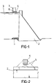
- Figure 1 shows a diagrammatic view in lateral elevation and in cross-section of a dam in which the initial phases have been carried out for putting the system for the manufacture and installation of selective intake towers , which constitutes the subject of the present invention, into practice, and more specifically the foundation phase and the production of the floating platform.
- Figure 2 shows a plan view of the whole shown in the previous figure.
- Figure 3 shows, in a diagrammatic view similar to that in Figure 1, a point in the process in which the tower is being launched.
- Figure 4 shows a view similar to that in Figure 3 but with the shaft of the tower totally finished and ready to effect positioning thereof.
- Figure 5 shows a view similar to that in Figure 4 during the positioning phase.
- Figure 6 shows a view similar to that in previous figures and corresponding to the final stage of ballasting and finishing the tower.
- Figure 7 shows a detail, in elevation and in cross-section, corresponding to one of the shields for temporary protection of one of the apertures of the tower.
- Figure 8 shows a detail, in plan view and in cross-section, at the level of one of the connection-window orifices, the window being provided with the corresponding sampling tubing, grille and protective shield.
- This platform (4) is fastened advantageously to the dam (2) with the collaboration of moorings or anchorages (5), as may be observed in Figure 2, anchorages which must permit the vertical oscillation movements of the actual reservoir as well as the downward displacement of said platform as the tower is manufactured thereon, only the drifting of the platform being prevented.
- the floating platform (4) is removed, as has been shown diagrammatically in Figure 3, from which point the buoyancy of the tower is controlled by means of interior ballasting thereof, specifically by means of supplying a variable mass of water (8) which will be all the greater, the greater the height of the shaft.
- the similarly definitive ballasting (12) thereof is performed, also cementing, and at a lower level, the gap (13) which remains between the actual tower and the dam (2), as may be observed also in Figure 6, it being possible for the tower to be topped by a chamber (14) where the means for actuating and inspection thereof are set up.
- the windows (15), of suitable size and position for the various intake points in the tower and, as appropriate, suitable for the outlet or discharge conduit, will be produced in the shaft or lateral wall (7) of the tower, these windows (15) remaining temporarily protected by means of closure shields (16), as is clearly visible in Figure 7, and, specifically, the windows corresponding to the said intake points being provided with the conventional grille (17) and with the optional presence of inlet tubing (18) along which the corresponding control valve will be set up, although, as stated previously, it is possible for these windows not to have inlet tubing, the corresponding gate being produced directly therein, the means for control and actuation for said valves and/or gates being set up, in any case, inside the tower.
- discharge of the water from the interior of the tower may the place via pumping, although it will normally be performed by gravity, in which case the corresponding discharge window (15) will be connected advantageously to a preexisting duct in the actual dam (2) or to a duct which has been advantageously made therein, with a diameter suited to the anticipated discharge flow.
Landscapes
- Engineering & Computer Science (AREA)
- General Engineering & Computer Science (AREA)
- Mechanical Engineering (AREA)
- Civil Engineering (AREA)
- Structural Engineering (AREA)
- Barrages (AREA)
- Investigation Of Foundation Soil And Reinforcement Of Foundation Soil By Compacting Or Drainage (AREA)
- Other Liquid Machine Or Engine Such As Wave Power Use (AREA)
Applications Claiming Priority (2)
| Application Number | Priority Date | Filing Date | Title |
|---|---|---|---|
| ES9101405 | 1991-06-12 | ||
| ES9101405A ES2035779B1 (es) | 1991-06-12 | 1991-06-12 | Sistema de fabricacion e instalacion de torres de tomas selectivas en embalses. |
Publications (1)
| Publication Number | Publication Date |
|---|---|
| EP0518802A1 true EP0518802A1 (de) | 1992-12-16 |
Family
ID=8272672
Family Applications (1)
| Application Number | Title | Priority Date | Filing Date |
|---|---|---|---|
| EP92500070A Withdrawn EP0518802A1 (de) | 1991-06-12 | 1992-06-10 | Verfahren zum Aufbau und Einrichtung von Wasserentnahmevorrichtungen in Staubecken |
Country Status (3)
| Country | Link |
|---|---|
| EP (1) | EP0518802A1 (de) |
| CA (1) | CA2071018A1 (de) |
| ES (1) | ES2035779B1 (de) |
Cited By (4)
| Publication number | Priority date | Publication date | Assignee | Title |
|---|---|---|---|---|
| WO2011115504A3 (en) * | 2010-03-18 | 2012-01-26 | Seatower As | Device for improving floating stability and floating ability of floating structures |
| CN106284239A (zh) * | 2016-08-08 | 2017-01-04 | 国家电网公司 | 一种大型坝式水电站初步选址方法 |
| CN114687322A (zh) * | 2022-05-10 | 2022-07-01 | 中国电建集团成都勘测设计研究院有限公司 | 适用于竖井闸室抛物孔快速封堵的封堵装置及方法 |
| CN120250656A (zh) * | 2025-06-04 | 2025-07-04 | 中国水利水电第十二工程局有限公司 | 一种高寒地区帷幕灌浆冬季施工方法 |
Families Citing this family (2)
| Publication number | Priority date | Publication date | Assignee | Title |
|---|---|---|---|---|
| DE19800005A1 (de) * | 1998-01-02 | 1999-07-08 | Linde Ag | Verfahren und Vorrichtung zum Bereitstellen von See- oder Meerwasser aus großen Tiefen |
| CN109519004A (zh) * | 2018-11-19 | 2019-03-26 | 上海市政工程设计研究总院(集团)有限公司 | 一种预制装配式水池及其装配方法 |
Citations (4)
| Publication number | Priority date | Publication date | Assignee | Title |
|---|---|---|---|---|
| US3249664A (en) * | 1961-12-21 | 1966-05-03 | Georgii Hans Christer | Method of making an elongated hollow concrete body |
| US4054034A (en) * | 1976-07-01 | 1977-10-18 | Robert Warren Hyre | Method for casting concrete tanks in water |
| GB2024293A (en) * | 1978-06-26 | 1980-01-09 | Dev Operationnels Comp Gen | Method for the building and putting in place of a sea platform with a gravity resting base and means for implementing such a method |
| GB2225365A (en) * | 1988-11-15 | 1990-05-30 | Norwegian Contractors | Building and installing offshore gravity platforms |
-
1991
- 1991-06-12 ES ES9101405A patent/ES2035779B1/es not_active Expired - Fee Related
-
1992
- 1992-06-10 EP EP92500070A patent/EP0518802A1/de not_active Withdrawn
- 1992-06-11 CA CA002071018A patent/CA2071018A1/en not_active Abandoned
Patent Citations (4)
| Publication number | Priority date | Publication date | Assignee | Title |
|---|---|---|---|---|
| US3249664A (en) * | 1961-12-21 | 1966-05-03 | Georgii Hans Christer | Method of making an elongated hollow concrete body |
| US4054034A (en) * | 1976-07-01 | 1977-10-18 | Robert Warren Hyre | Method for casting concrete tanks in water |
| GB2024293A (en) * | 1978-06-26 | 1980-01-09 | Dev Operationnels Comp Gen | Method for the building and putting in place of a sea platform with a gravity resting base and means for implementing such a method |
| GB2225365A (en) * | 1988-11-15 | 1990-05-30 | Norwegian Contractors | Building and installing offshore gravity platforms |
Non-Patent Citations (1)
| Title |
|---|
| PATENT ABSTRACTS OF JAPAN vol. 9, no. 242 (M-417)(1965) 28 September 1985 & JP-A-60 95 014 ( MITSURU HISADA ) 28 May 1985 * |
Cited By (6)
| Publication number | Priority date | Publication date | Assignee | Title |
|---|---|---|---|---|
| WO2011115504A3 (en) * | 2010-03-18 | 2012-01-26 | Seatower As | Device for improving floating stability and floating ability of floating structures |
| CN106284239A (zh) * | 2016-08-08 | 2017-01-04 | 国家电网公司 | 一种大型坝式水电站初步选址方法 |
| CN106284239B (zh) * | 2016-08-08 | 2018-04-24 | 国家电网公司 | 一种大型坝式水电站初步选址方法 |
| CN114687322A (zh) * | 2022-05-10 | 2022-07-01 | 中国电建集团成都勘测设计研究院有限公司 | 适用于竖井闸室抛物孔快速封堵的封堵装置及方法 |
| CN114687322B (zh) * | 2022-05-10 | 2023-05-26 | 中国电建集团成都勘测设计研究院有限公司 | 适用于竖井闸室抛物孔快速封堵的封堵装置及方法 |
| CN120250656A (zh) * | 2025-06-04 | 2025-07-04 | 中国水利水电第十二工程局有限公司 | 一种高寒地区帷幕灌浆冬季施工方法 |
Also Published As
| Publication number | Publication date |
|---|---|
| ES2035779A1 (es) | 1993-04-16 |
| CA2071018A1 (en) | 1992-12-13 |
| ES2035779B1 (es) | 1993-11-01 |
Similar Documents
| Publication | Publication Date | Title |
|---|---|---|
| EP1029131B1 (de) | Fischdurchlass | |
| RU2539238C2 (ru) | Устройство для улучшенного использования водной энергии на существующих средствах запруживания воды | |
| EP3204559B1 (de) | Schwimmender damm oder insel und verfahren zur herstellung davon | |
| CN103993581A (zh) | 治山治水贮水防灾发电航运翻江填海造地系统工程 | |
| CN109537631B (zh) | 一种自潜悬浮式水下隧道装置 | |
| CN105735210B (zh) | 隧洞式仿自然鱼道结合鱼闸的布置结构及其使用方法 | |
| EP3683438A1 (de) | Pumpspeicherwerk in einem gewässer und verfahren zum betrieb | |
| US20020044835A1 (en) | Selective reservoir withdrawal system | |
| EP0518802A1 (de) | Verfahren zum Aufbau und Einrichtung von Wasserentnahmevorrichtungen in Staubecken | |
| EP2725143B1 (de) | Pumpspeicherwerk zur Energiespeicherung | |
| KR20230162941A (ko) | 해상 풍력 터빈용 기초 | |
| CN117536173B (zh) | 一种利用充水浮体闸门适应上游水位变化的鱼道 | |
| JPS589206B2 (ja) | 陸上プラント建設方法 | |
| US5284402A (en) | System for the manufacture and installation of selective intake towers in reservoirs | |
| CN111945676B (zh) | 水箱、闸门启闭装置以及闸门启闭装置控制方法 | |
| CN109572950A (zh) | 一种用于水面光伏电站的自动适应水位的防护装置 | |
| CN204326028U (zh) | 一种可控挡水钢板坝 | |
| CZ297902B6 (cs) | Pohyblivá, pretékaná a podtékaná vodní elektrárna | |
| JP3427324B2 (ja) | チェーンゲート装置 | |
| DE19641862B4 (de) | Schwimmkraftwerk | |
| DE102004025769A1 (de) | Einrichtungen zur Flussinfrastruktur-Modernisierung | |
| RU65509U1 (ru) | Селективное водозаборное устройство | |
| CN104452683B (zh) | 一种可控挡水钢面板坝 | |
| Cochrane | Operation of spillways in Northwest Projects | |
| KR20250054349A (ko) | 착저식 해상 작업대 및 그 운용 방법 |
Legal Events
| Date | Code | Title | Description |
|---|---|---|---|
| PUAI | Public reference made under article 153(3) epc to a published international application that has entered the european phase |
Free format text: ORIGINAL CODE: 0009012 |
|
| AK | Designated contracting states |
Kind code of ref document: A1 Designated state(s): AT BE CH DE DK FR GB GR IT LI LU MC NL PT SE |
|
| 17P | Request for examination filed |
Effective date: 19930616 |
|
| 17Q | First examination report despatched |
Effective date: 19940624 |
|
| 18D | Application deemed to be withdrawn |
Effective date: 19951024 |