EP0519060B1 - Appareil de dilatation et d'imagerie - Google Patents
Appareil de dilatation et d'imagerie Download PDFInfo
- Publication number
- EP0519060B1 EP0519060B1 EP92904268A EP92904268A EP0519060B1 EP 0519060 B1 EP0519060 B1 EP 0519060B1 EP 92904268 A EP92904268 A EP 92904268A EP 92904268 A EP92904268 A EP 92904268A EP 0519060 B1 EP0519060 B1 EP 0519060B1
- Authority
- EP
- European Patent Office
- Prior art keywords
- balloon
- imaging device
- lumen
- tubing
- catheter
- Prior art date
- Legal status (The legal status is an assumption and is not a legal conclusion. Google has not performed a legal analysis and makes no representation as to the accuracy of the status listed.)
- Expired - Lifetime
Links
Images


Classifications
-
- A—HUMAN NECESSITIES
- A61—MEDICAL OR VETERINARY SCIENCE; HYGIENE
- A61M—DEVICES FOR INTRODUCING MEDIA INTO, OR ONTO, THE BODY; DEVICES FOR TRANSDUCING BODY MEDIA OR FOR TAKING MEDIA FROM THE BODY; DEVICES FOR PRODUCING OR ENDING SLEEP OR STUPOR
- A61M25/00—Catheters; Hollow probes
- A61M25/10—Balloon catheters
- A61M25/104—Balloon catheters used for angioplasty
-
- A—HUMAN NECESSITIES
- A61—MEDICAL OR VETERINARY SCIENCE; HYGIENE
- A61B—DIAGNOSIS; SURGERY; IDENTIFICATION
- A61B8/00—Diagnosis using ultrasonic, sonic or infrasonic waves
- A61B8/12—Diagnosis using ultrasonic, sonic or infrasonic waves in body cavities or body tracts, e.g. by using catheters
-
- A—HUMAN NECESSITIES
- A61—MEDICAL OR VETERINARY SCIENCE; HYGIENE
- A61B—DIAGNOSIS; SURGERY; IDENTIFICATION
- A61B8/00—Diagnosis using ultrasonic, sonic or infrasonic waves
- A61B8/44—Constructional features of the ultrasonic, sonic or infrasonic diagnostic device
- A61B8/4444—Constructional features of the ultrasonic, sonic or infrasonic diagnostic device related to the probe
- A61B8/445—Details of catheter construction
-
- A—HUMAN NECESSITIES
- A61—MEDICAL OR VETERINARY SCIENCE; HYGIENE
- A61M—DEVICES FOR INTRODUCING MEDIA INTO, OR ONTO, THE BODY; DEVICES FOR TRANSDUCING BODY MEDIA OR FOR TAKING MEDIA FROM THE BODY; DEVICES FOR PRODUCING OR ENDING SLEEP OR STUPOR
- A61M25/00—Catheters; Hollow probes
- A61M25/10—Balloon catheters
- A61M2025/1043—Balloon catheters with special features or adapted for special applications
- A61M2025/1079—Balloon catheters with special features or adapted for special applications having radio-opaque markers in the region of the balloon
Definitions
- the present invention relates generally to percutaneous transluminal coronary angioplasty (PTCA) and ultrasonic imaging, and more particularly to a single apparatus having both capabilities.
- PTCA percutaneous transluminal coronary angioplasty
- Intravascular balloon catheters that include ultrasonic imaging devices provide an effective alternative to coronary bypass surgery.
- Transluminal angioplasty surgery utilizes an elongated, flexible catheter having an inflatable balloon at its distal end that is inserted at an appropriate position in a vascular system of a patient. After the catheter is inserted into the vascular system, its balloon is routed to a stenosis. Once the balloon is properly positioned relative to the stenotic lesion, it is inflated with fluid under relatively high pressure. As the balloon expands, it dilates the stenosis, thus allowing blood to flow more freely.
- a contrast compound such as a substance that is opaque to radiation
- the physician first inserts a guide wire into the occluded vessel. After the guide wire has reached the stenosis or the occluded vessel, a tubular catheter having a lumen for the guide wire is pushed along the guide wire and guided by the guide wire until fluoroscopy reveals that the balloon is located within the stenosis. The balloon is then inflated to dilate the stenosis. When the balloon is deflated and removed from the vessel, blood is able to flow more freely through the enlarged stenosis.
- a contrast compound such as a substance that is opaque to radiation
- fluoroscopy enables the physician to locate the position of the stenosis, it fails to provide the physician with detailed, real-time images of the anatomy causing the stenosis during and after the dilation procedure.
- the limitations of fluoroscopy has lead to attempts to improve upon imaging of the stenosis being treated.
- One such method uses two catheters, wherein one catheter has an ultrasonic imaging device at its distal end and the other catheter has the inflatable balloon at its distal end.
- the balloon catheter is first inserted into the vessel along the guide wire, positioned within the stenosis, and the balloon is inflated to dilate the stenosis.
- the balloon catheter is then removed and the imaging catheter is inserted to enable the physician to examine the stenosis and determine if further treatment is needed.
- U.S. Patent No. 4,917,097 to Proudian et al. also discloses a catheter having both dilating and imaging capabilities, wherein the imaging device is positioned at a distal end of the balloon.
- the capability of the Proudian balloon to enter very small diameter stenoses is limited by the relatively large diameter of the imaging device. In order to optimize these types of catheters, it is important for the balloon to be able to enter even the very narrow stenoses.
- Imaging devices typically include an imaging array that enables the device only to image an integral (or "slice") of the stenosis immediately adjacent to the periphery of the array. Therefore, the entire balloon catheter must be moved in order for the physician to examine additional integrals of the stenosis.
- a primary object of the present invention to provide a dilating assembly capable of both dilating a stenosis of a blood vessel with an inflatable balloon and imaging the stenosis with an ultrasonic imaging device, wherein the inclusion of the imaging device on the catheter does not affect the ability of the balloon to achieve a very low profile and be able to enter very narrow stenoses.
- Another object of the present invention is to provide a dilating assembly capable of both achieving a low profile of very small diameter and dilating a stenosis while simultaneously imaging the entire portion of the stenosis being dilated.
- An additional object of the present invention is to provide an imaging catheter capable of providing a high quality image.
- the invention generally provides a dilating and imaging apparatus for attaching to and receiving pressurized fluid from a distal end of a catheter.
- the apparatus includes an inflatable balloon and an imaging device and is characterized in that the imaging device is positioned behind an expandable portion of the balloon in a second lumen formed by a tubular part of the balloon through which pressurized fluid flows into the balloon. This enables the balloon on deflation to achieve a smaller diameter than that of the imaging device, this aspect enabling the apparatus to enter a stenosis having a smaller diameter than the imaging device.
- the imaging device can be maneuvered within the balloon while the balloon is inflated and dilating the stenosis.
- FIGURE 1a illustrates a dilating and imaging apparatus 10 according to the present invention as it is being utilized in a coronary artery 12 of a heart 14.
- the coronary artery 12 contains a buildup of fatty material or plaque 16 that is causing the coronary artery 12 to become occluded or have a stenosis.
- the occluded section or stenosis 16 of the artery 12 may be treated by inserting a balloon 18 of the dilating apparatus 10, in a low profile or deflated state, into the artery 12 by using a catheter assembly 20.
- the catheter assembly 20 is a three-part assembly, having a guide wire 22, a guide catheter 24 for threading through large arteries such as the aorta 26, and a smaller diameter catheter 28 that fits inside the guide catheter 24.
- the catheter assembly 20 includes a tri-arm adapter 30 having a signal processor port 32, a guide wire insert port 34, and an inflation port 36 that is in communication with a fluid lumen in the catheter 28.
- the tri-arm adaptor 30 enables a signal processor 38 (that is linked to a video display 40), a guide wire 22, and an inflation source 42 all to be interconnected within the smaller catheter 28 and to communicate with the dilating and imaging apparatus 10.
- the smaller catheter 28 is inserted into the larger guide catheter 24 by means of a luer lock connector or angioplasty manifold 43 before entering the heart 14.
- the smaller diameter catheter 28 and the larger diameter catheter 24 may be made of a suitable, flexible material such as polyolefin or polyvinylchloride.
- the smaller diameter catheter 28 is inserted.
- the guide wire 22 is first extended into the artery 12, followed by the smaller catheter 28, which includes the balloon 18 on a distal end of the catheter 28.
- a single dilating and imaging apparatus is provided that is capable of achieving a low profile having a smaller diameter than that of an imaging device located within a proximal sleeve of the balloon.
- Means are provided for communicating the flow of pressurized fluid past the imaging device before entering an expandable portion of the balloon.
- an imaging device 44 is positioned within the proximal sleeve 46 of the balloon 18 in order to enable the balloon 18 to achieve a low profile having a smaller diameter than that of the imaging device 44. This is possible because the imaging device 44 is positioned within the proximal sleeve 46 that is behind an expandable portion of the balloon 18.
- the expandable portion of the balloon 18 is that portion of the balloon 18 between the proximal sleeve 46 and the distal sleeve 52.
- the imaging device 44 includes a central bore 41 for maintaining a first lumen 39 through the imaging device 44 and into the balloon 18.
- the central bore 41 enables the guide wire 22, which is passed through a tubing 50, to pass through the center of the imaging device 44.
- FIG. 1b shows how the deflated balloon 18 is able to follow the guide wire 22 and enter a stenosis 16 having a smaller diameter than the imaging device 44 because the imaging device 44 is positioned in the proximal sleeve 46 of the balloon 18.
- the balloon 18 enters the stenosis or occluded artery 16 in a low profile or deflated state. Once the balloon 18 is properly positioned within the stenosis 16, pressurized fluid communicated to the interior of the balloon 18 via the catheter 28 causes the balloon 18 to inflate and dilate the stenosis 16. After the stenosis 16 has been dilated by the inflated balloon 18, the balloon is deflated by withdrawing the pressurized fluid.
- the proximal sleeve 46 of the balloon 18, which contains the imaging device 44, then may be positioned inside the dilated stenosis 16 by further inserting the catheter 28 into the artery 12.
- An imaging array 48 located within the imaging device 44 is highly directional and, therefore, the imaging device 44 must be able to enter the dilated stenosis in order to generate a complete image of the dilated stenosis 16.
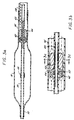
- FIGS. 2a and 2b are cross-sections of one embodiment of the present invention.
- FIG. 2b is an enlarged cross-sectional view of the proximal sleeve 46 and the imaging device 44 shown in FIG. 2a.
- the tubing 50 having a first lumen 39 extends through the interior of the balloon 18.
- the tubing 50 runs parallel with a longitudinal axis of the catheter 28.
- a distal sleeve 52 of the balloon 18 is hermetically sealed, or joined, to a distal end 54 of the tubing 50, and the proximal sleeve 46 of the balloon 18 is hermetically sealed, or joined, to an outer surface of the smaller diameter catheter 28, thereby sealing off the interior of the balloon 18 from the external environment.
- a proximal end 53 of the tubing 50 is connected to a distal end of a guide wire lumen (see FIGS. 7a-c) of the catheter 28.
- the balloon 18 may be secured to the tubing 50 with a sealant or by heating the balloon 18 in order to constrict the distal sleeve 52 and the proximal sleeve 46 around the tubing 50 and the catheter 28, respectively.
- the balloon 18 is coaxial to and encompasses the tubing 50 which creates a second lumen 56 between an inner wall of the balloon 18 and an outer surface of the tubing 50.
- Means for communicating the flow of pressurized fluid past the imaging device 44 are provided by an annular passageway 45 within the second lumen 56.
- the annular passageway 45 is formed between a peripheral surface of the imaging device 44 and an inner wall of the proximal sleeve 46 such that the pressurized fluid is in communication with the interior of the balloon 18.
- the imaging device 44 is in direct contact with the pressurized fluid, and therefore, should be insulated from the pressurized fluid by a protective sealant.
- One type of protective sealant that may be used is a thin coating of parylene polymer. Parylene polymer is a product trade name and manufactured by Union Carbide Corporation.
- a fluoroscopically visible cylindrical marker band 58 is secured around the tubing 50 at a location within the balloon 18.
- Another marker band 60 is located within the imaging device 44.
- the marker bands 58 and 60 enable the position of the balloon 18 and the imaging array 44 to be monitored as the catheter 28 is inserted into the vascular system of the patient.
- Additional marker bands may be secured to the apparatus 10 in order to monitor specific sections of the apparatus 10.
- an additional marker band (not shown) may be secured to the distal end of the tubing 50 in order to monitor the position of the distal sleeve 52.
- the marker bands may be fabricated of gold or other suitable dense metal.
- the marker bands typically have a wall thickness on the order of 0.0076 cm (0.003 inches) and an internal diameter corresponding to the surface diameter of the tubing 50 to which the marker bands are to be mounted.
- a micro-cable 62 that extends through the second lumen 56 back to the proximal end of the catheter 28, interlinks electronics of the imaging device 44 to the signal processor 38 (FIG. 1).
- the micro-cable 62 is about 0.017 inches in diameter and has a number of individual insulated conductors.
- the signal processor 38 is connected to a video display 40 that displays an image of the stenosis 16 as detected by the imaging array 48.
- the imaging device 44 is situated within the proximal sleeve 46 by mounting means.
- the mounting means may include securing the imaging device 44 directly to the tubing 50.
- the tubing 50 is spliced at a location within the proximal sleeve 46 and a tubing coupling 64, to which the imaging device 44 is secured, is inserted into opposing ends of the slice.
- the tubing coupling 64 is more sturdy than the tubing 50 and provides a stronger mounting for the imaging device 44.
- the tubing coupling 64 can be constructed of a sturdy material such as polyamide.
- FIGS. 3a-3c illustrate another embodiment of the present invention, wherein another communicating means and mounting means are provided.
- FIG. 3a shows a cross-sectional view of the apparatus 10 and
- FIG. 3b shows an enlarged view of the proximal sleeve 46 which contains the imaging device 44.
- the communicating means include both an annular passageway 45 and a plurality of central passageways 66.
- the plurality of central passageways 66 are located between an outer surface 67 of the tubing 50 and an inner surface 69 of the central bore 41 (FIG. 3c).
- FIG. 3c shows a cross-sectional view of the imaging device 44 shown in and taken along line 3c-3c of FIG. 3b.
- the plurality of central passageways 66 run parallel with the tubing 50 and are positioned between the inner surface 69 of the central bore 41 and the outer surface 67 of the tubing 50.
- the mounting means include mounting segments 68 of the central bore 41 which are secured to portions of the outer surface of the tubing 50. This embodiment increases the flow rate of the pressurized fluid to and from the balloon 18, but it is more difficult and costly to produce.
- FIGS. 4a and 4b illustrate another embodiment of the invention wherein the imaging array 48 is exposed directly to blood in the artery.
- the feature enables the apparatus 10 to provide a high quality image because there is no attenuation or reflection (echo) resulting from a barrier between the imaging array 48 and the inner walls of the artery 12, except for the blood which provides a medium for ultrasonic waves generated by the imaging array 48.
- this configuration also positions the imaging device 44 behind the expandable portion of the balloon 18.
- the imaging device 44 includes a carrier extension 70 that is attached to the imaging device 44.
- the carrier extension may be formed from a rigid plastic, epoxy, metal or suitable material.
- the proximal sleeve is spliced to create an anterior end 72 and a posterior end 74.
- Mounting means are provided by securing the carrier extension 70 to the anterior end 72 and securing the posterior end 74 to the imaging device 44.
- Communicating means are provided by a gap 76 between the inner wall 47 of the central bore 41 and the outer surface of the tubing 50.
- a tubing coupling 64 may be used to provide a section of the tubing 50 that is smaller in diameter and has thinner walls. This embodiment allows for the gap 76 to exist between the outer surface of the tubing coupling 64 and the inner wall 47 of the central bore 41.
- FIG. 5 illustrates another embodiment of the present invention wherein the proximal sleeve 46 includes a lumen attachment 78 located between the imaging device 44 and the expandable portion of the balloon 18.
- the lumen attachment is a ring-shaped spacer that serves to position the proximal sleeve 46 at a radially spaced position from the tubing 50.
- the ring-shaped spacer is made of any suitable rigid material.
- An inner wall of the attachment 78 is mounted to the outer surface of the tubing coupling 64, and an outer surface of the attachment 78 is mounted to the inner wall of the proximal sleeve 46.
- the lumen attachment 78 also includes flow channels 80 that enable the pressurized fluid to pass through the lumen attachment 80.
- the communicating means include a gap 82 similar to gap 76 of FIG. 4a.
- the flow channels 80 in combination with the gap 82 provide means for communicating the pressurized fluid to the balloon 18.
- Means for mounting the imaging device 44 are provided by securing the outer periphery of the imaging device 44 to the inner wall of the proximal sleeve 46.
- This embodiment provides additional mechanical support to the proximal sleeve 46.
- the prior embodiment illustrated in FIG. 2a places a great deal of operational forces on the proximal sleeve 46.
- the lumen attachment 78 in this embodiment provides additional support to the proximal sleeve 46 in order to lessen the operational forces on the proximal sleeve 46.
- FIG. 6a illustrates another important aspect of the present invention, wherein the imaging device 44 is slidably mounted to the tubing 50 so as to enable the imaging device 44 to generate a complete image of the stenosis 16 while the inflated balloon 18 simultaneously dilates the stenosis 16 in this embodiment.
- a push wire 84 is attached to the imaging device 44 and extends back through the second lumen 56 to the proximal end of the catheter 28.
- the push wire 84 is a flexible hypotube (thin-walled tube) wherein a micro-cable 63 is located inside the push wire 84.
- the diameter of the push wire 84 is approximately 0.0356 cm (0.014 inches).
- the push wire 84 enables a surgeon to remotely maneuver the imaging device 44 within the balloon 18 while the balloon 18 is inflated.
- the surgeon can image the entire portion of the stenosis 16 being dilated by the inflated balloon 18 by sliding the imaging device 44 along the entire length of the tubing 50 that is located within the expandable portion of the balloon 18.
- a portion of the tubing 50 that is located within the proximal sleeve 46 and the expandable portion of the balloon 18 is preferably be replaced with a sturdier micro-tube 86 in order to enable the imaging device 44 to slide more easily within the balloon 18.
- the micro-tube 86 is similar to the tubing coupling 64 because it is inserted in opposing ends of a splice in the tubing 50.
- the micro-tube 86 may also be made from polyamide.
- the imaging device 44 is initially positioned within the proximal sleeve 46 when the balloon 18 is deflated and being inserted into the stenosis 16. Positioning the device 44 within the proximal sleeve 46 enables the balloon 18 to achieve a low profile that is not restricted by the diameter of the imaging device 44. After the balloon 18 is inflated with pressurized fluid, the surgeon then uses the push wire 84 to push the imaging device out of the proximal sleeve 46 and into the expandable portion of the balloon 18. By sliding the imaging device 44 along the micro-tube 86, the surgeon is able to image all sections of the stenosis 16 which are being dilated by the inflated balloon.
- the surgeon may then deflate the balloon 18 and image the stenosis 16 in order to determine whether the stenosis 16 maintains a dilated form after the balloon 18 is removed.
- the imaging device 44 is first maneuvered back into the proximal sleeve 46 before deflating the balloon 18.
- the stenosis 16 is imaged by inserting the proximal sleeve 46, which contains the imaging device 44, further into the stenosis 16.
- FIG. 7a illustrates a coaxial lumen arrangement wherein the pressurized fluid, micro-cable 62 (or push wire 84) may pass through the outer lumen 90 and the guide wire 22 may pass through the inner lumen 92.
- FIG. 7b illustrates a side-by-side lumen arrangement wherein the guide wire 22 may pass through lumen 94, and the pressurized fluid and micro-cable 62 may pass through lumen 96.
- FIG. 7a illustrates a coaxial lumen arrangement wherein the pressurized fluid, micro-cable 62 (or push
- FIG. 7c discloses a tri-lumen arrangement wherein the guide wire 22 may pass through lumen 98, the pressurized fluid may pass through lumen 100, and the micro-cable 62 (or push wire 84) may pass through lumen 102.
- the apparatus of the present invention is simply secured to the distal end of the catheter in a conventional manner so that the guide wire 22, pressurized fluid, and micro-cable 62 (or push wire 84) communicate correctly with the apparatus.
- these illustrated lumens are only exemplary of the different catheters that may be used with this invention and are not intended to limit the invention to only those catheters illustrated herein.
Landscapes
- Health & Medical Sciences (AREA)
- Life Sciences & Earth Sciences (AREA)
- Heart & Thoracic Surgery (AREA)
- Animal Behavior & Ethology (AREA)
- Biophysics (AREA)
- Veterinary Medicine (AREA)
- Public Health (AREA)
- General Health & Medical Sciences (AREA)
- Engineering & Computer Science (AREA)
- Biomedical Technology (AREA)
- Surgery (AREA)
- Molecular Biology (AREA)
- Physics & Mathematics (AREA)
- Medical Informatics (AREA)
- Radiology & Medical Imaging (AREA)
- Pathology (AREA)
- Nuclear Medicine, Radiotherapy & Molecular Imaging (AREA)
- Vascular Medicine (AREA)
- Child & Adolescent Psychology (AREA)
- Pulmonology (AREA)
- Anesthesiology (AREA)
- Hematology (AREA)
- Media Introduction/Drainage Providing Device (AREA)
- Ultra Sonic Daignosis Equipment (AREA)
Abstract
Claims (12)
- Appareil de dilatation et d'imagerie (10) fixée à un cathéter (28), le cathéter ayant des extrémités distale et proximale, un orifice de fluide (90, 96 ou 100) et un orifice (92, 94 ou 98) d'un fil métallique de guidage recevant un fil métallique de guidage (22), l'appareil comprenant :un tube (50) ayant des extrémités distale et proximale et un premier orifice (39) en communication avec l'orifice du fil métallique de guidage dans le cathéter, où l'extrémité proximale (53) du tube est connectée à l'extrémité distale du cathéter;un ballon gonflable (18) ayant des manchons distal et proximal (52, 46), le ballon étant coaxial avec et entourant le tube (50), le manchon distal (52) étant scellé à l'extrémité distale (54) du tube et le manchon proximal (46) se joignant à l'extrémité distale du cathéter, et un dispositif d'imagerie (44) dans le ballon;caractérisé en ce que le ballon (18) entoure le tube (56) afin de former un second orifice (56) entre une surface externe du tube et une surface interne du manchon proximal (46), de manière que le fluide sous pression de l'orifice du fluide du cathéter puisse s'écouler vers l'intérieur du ballon via le second orifice (56) et gonfler le ballon;le dispositif d'imagerie (44) a un perçage central (41) pour permettre au fil métallique de guidage de passer à travers le dispositif d'imagerie et dans le tube;des moyens (64; 68; 72; 74) sont prévus pour monter le dispositif d'imagerie dans le manchon proximal (46) du ballon de façon que le dispositif d'imagerie soit placé derrière la portion dilatable du ballon et en amont de l'écoulement du fluide sous pression dans le ballon, afin de permettre au ballon d'atteindre un profil bas ayant un diamètre plus petit que celui du dispositif d'imagerie; etdes moyens (45, 66, 76 ou 82) sont prévus pour communiquer l'écoulement du fluide sous pression au-delà du dispositif d'imagerie avant d'entrer dans la portion dilatable du ballon.
- Appareil selon la revendication 1 où le fil métallique de guidage et l'orifice de fluide (92, 90) du cathéter sont coaxiaux.
- Appareil selon la revendication 1 où le fil métallique de guidage et l'orifice de fluide (94, 96) du cathéter sont en agencement côte à côte.
- Appareil selon la revendication 1 où les moyens de montage (64) comportent un moyen pour monter le dispositif d'imagerie (44) sur le tube et les moyens de communication (45) comprennent un passage annulaire pour que le fluide sous pression s'écoule entre une surface périphérique du dispositif d'imagerie et une paroi interne du manchon proximal, de façon que le fluide sous pression soit en contact avec le dispositif d'imagerie.
- Appareil selon la revendication 4 où les moyens de communication comprennent un certain nombre de passages centraux (66) permettant au fluide sous pression de s'écouler entre les parois internes du perçage central et une surface externe du tube de manière que le fluide sous pression puisse passer à travers le dispositif et les moyens de montage comprennent de plus les segments de montage (68) sur la paroi interne du perçage central qui sont fixés à la surface externe du tube.
- Appareil selon la revendication 1, dans lequel le manchon proximal du ballon a une discontinuité exposant un agencement d'imagerie (48) du dispositif d'imagerie à un contact direct avec le sang à l'extérieur de l'appareil afin d'augmenter la sensibilité de l'imagerie de l'agencement, les moyens de montage comprennent des moyens pour fixer le dispositif à la paroi interne du manchon proximal et les moyens de communication comprennent un espace (76) entre une paroi interne du perçage central et une surface externe du tube qui permet au fluide sous pression de passer à travers le dispositif d'imagerie.
- Appareil selon la revendication 6, comprenant de plus :une extension du support (70) sur le dispositif d'imagerie, où une extrémité antérieure (72) de la discontinuité se monte sur l'extension de support et une extrémité postérieure (74) de la discontinuité se monte sur le dispositif d'imagerie.
- Appareil selon la revendication 1, comprenant de plus :une fixation à orifices (78) pour fixer une portion du manchon proximal du ballon en une position radialement espacée du tube, la fixation à orifices étant placée entre le dispositif d'imagerie et la portion dilatable du ballon et la fixation à orifices comprenant des canaux d'écoulement (80) permettant au fluide sous pression de passer à travers la fixation à orifices à partir du second orifice jusqu'à l'intérieur du ballon.
- Appareil selon la revendication 8 où le moyen de montage comprend un moyen pour fixer une surface périphérique du dispositif d'imagerie à une paroi interne du manchon proximal du ballon et les moyens de communication comprennent un espace (82) entre une paroi interne du perçage central et une surface externe du tube, qui permet au fluide sous pression de passer à travers le dispositif d'imagerie.
- Appareil de dilatation et d'imagerie fixé à un cathéter (28), le cathéter ayant des extrémités distale et proximale, un orifice de fluide (90, 96 ou 100) et un orifice de fil métallique de guidage (92, 94 ou 98) pour recevoir un fil métallique de guidage, l'appareil comprenant :un dispositif d'imagerie (44);un tube (50) ayant des extrémités distale et proximale et un premier orifice (39) pour recevoir le fil métallique de guidage communiqué au premier orifice à partir de l'orifice du fil métallique de guidage dans le cathéter, où l'extrémité proximale du tube est connectée à une extrémité distale de l'orifice du fil métallique de guidage du cathéter;un ballon gonflable (18) ayant des extrémités distale et proximale (52, 46), le ballon étant coaxial avec et entourant le tube afin de former un second orifice entre une surface externe du tube et une surface interne du manchon proximal, le manchon distal se joignant à l'extrémité distale du tube et le manchon proximal (46) se joignant à l'extrémité distale du cathéter, de façon que le fluide sous pression de l'orifice du fluide dans le cathéter puisse s'écouler vers l'intérieur du ballon via le second orifice et gonfler le ballon;caractérisé en ce quele dispositif d'imagerie (44) est monté coulissant sur le tube pour faire glisser le dispositif le long du tube à partir d'une position dans le manchon proximal jusqu'à une position dans la portion dilatable du ballon afin de permettre au ballon d'atteindre un profil bas ayant un diamètre plus petit que celui du dispositif d'imagerie;un fil métallique à pousser (84) est attaché au dispositif d'imagerie, qui s'étend à travers le second orifice pour retourner à l'extrémité proximale du cathéter afin de commander à distance le coulissement du dispositif le long du tube; et en ce quedes moyens sont prévus pour communiquer l'écoulement du fluide sous pression au-delà du dispositif d'imagerie quand il est placé dans le manchon proximal du ballon afin de gonfler le ballon.
- Appareil selon la revendication 10 où le fil métallique de guidage et l'orifice du fluide (92, 90) du cathéter sont coaxiaux.
- Appareil selon la revendication 10 où le fil métallique de guidage et l'orifice du fluide (94, 96) du cathéter sont en agencement côte à côte.
Applications Claiming Priority (3)
| Application Number | Priority Date | Filing Date | Title |
|---|---|---|---|
| US638192 | 1984-08-06 | ||
| US07/638,192 US5167233A (en) | 1991-01-07 | 1991-01-07 | Dilating and imaging apparatus |
| PCT/US1991/009821 WO1992011809A1 (fr) | 1991-01-07 | 1991-12-31 | Appareil de dilatation et d'imagerie |
Publications (3)
| Publication Number | Publication Date |
|---|---|
| EP0519060A1 EP0519060A1 (fr) | 1992-12-23 |
| EP0519060A4 EP0519060A4 (en) | 1993-02-24 |
| EP0519060B1 true EP0519060B1 (fr) | 1996-09-25 |
Family
ID=24559021
Family Applications (1)
| Application Number | Title | Priority Date | Filing Date |
|---|---|---|---|
| EP92904268A Expired - Lifetime EP0519060B1 (fr) | 1991-01-07 | 1991-12-31 | Appareil de dilatation et d'imagerie |
Country Status (6)
| Country | Link |
|---|---|
| US (1) | US5167233A (fr) |
| EP (1) | EP0519060B1 (fr) |
| JP (1) | JP2552421B2 (fr) |
| CA (1) | CA2076378C (fr) |
| DE (1) | DE69122380T2 (fr) |
| WO (1) | WO1992011809A1 (fr) |
Cited By (1)
| Publication number | Priority date | Publication date | Assignee | Title |
|---|---|---|---|---|
| US6387035B1 (en) * | 1997-03-28 | 2002-05-14 | Jomed, Inc. | Catheter with swivel tip |
Families Citing this family (170)
| Publication number | Priority date | Publication date | Assignee | Title |
|---|---|---|---|---|
| US6029671A (en) * | 1991-07-16 | 2000-02-29 | Heartport, Inc. | System and methods for performing endovascular procedures |
| US5329496A (en) * | 1992-10-16 | 1994-07-12 | Duke University | Two-dimensional array ultrasonic transducers |
| US5744898A (en) * | 1992-05-14 | 1998-04-28 | Duke University | Ultrasound transducer array with transmitter/receiver integrated circuitry |
| US5453575A (en) | 1993-02-01 | 1995-09-26 | Endosonics Corporation | Apparatus and method for detecting blood flow in intravascular ultrasonic imaging |
| US20070016071A1 (en) * | 1993-02-01 | 2007-01-18 | Volcano Corporation | Ultrasound transducer assembly |
| US5368037A (en) | 1993-02-01 | 1994-11-29 | Endosonics Corporation | Ultrasound catheter |
| US5520647A (en) * | 1993-07-02 | 1996-05-28 | Pameda N.V. | Rapid withdrawal catheter |
| US5379772A (en) * | 1993-09-14 | 1995-01-10 | Intelliwire, Inc. | Flexible elongate device having forward looking ultrasonic imaging |
| US5411016A (en) | 1994-02-22 | 1995-05-02 | Scimed Life Systems, Inc. | Intravascular balloon catheter for use in combination with an angioscope |
| AU2238895A (en) * | 1994-04-01 | 1995-10-23 | Localmed, Inc. | Method and apparatus for performing multiple procedures |
| CA2188563C (fr) | 1994-04-29 | 2005-08-02 | Andrew W. Buirge | Extenseur au collagene |
| US5740808A (en) * | 1996-10-28 | 1998-04-21 | Ep Technologies, Inc | Systems and methods for guilding diagnostic or therapeutic devices in interior tissue regions |
| AU6404596A (en) * | 1995-06-30 | 1997-02-05 | Boston Scientific Corporation | Ultrasound imaging catheter with a cutting element |
| US7226417B1 (en) | 1995-12-26 | 2007-06-05 | Volcano Corporation | High resolution intravascular ultrasound transducer assembly having a flexible substrate |
| US6263229B1 (en) | 1998-11-13 | 2001-07-17 | Johns Hopkins University School Of Medicine | Miniature magnetic resonance catheter coils and related methods |
| US6898454B2 (en) | 1996-04-25 | 2005-05-24 | The Johns Hopkins University | Systems and methods for evaluating the urethra and the periurethral tissues |
| US6675033B1 (en) | 1999-04-15 | 2004-01-06 | Johns Hopkins University School Of Medicine | Magnetic resonance imaging guidewire probe |
| US7236816B2 (en) | 1996-04-25 | 2007-06-26 | Johns Hopkins University | Biopsy and sampling needle antennas for magnetic resonance imaging-guided biopsies |
| US5876426A (en) * | 1996-06-13 | 1999-03-02 | Scimed Life Systems, Inc. | System and method of providing a blood-free interface for intravascular light delivery |
| GB2315020A (en) * | 1996-07-11 | 1998-01-21 | Intravascular Res Ltd | Ultrasonic visualisation catheters |
| US5830145A (en) | 1996-09-20 | 1998-11-03 | Cardiovascular Imaging Systems, Inc. | Enhanced accuracy of three-dimensional intraluminal ultrasound (ILUS) image reconstruction |
| US5853368A (en) * | 1996-12-23 | 1998-12-29 | Hewlett-Packard Company | Ultrasound imaging catheter having an independently-controllable treatment structure |
| US5857974A (en) | 1997-01-08 | 1999-01-12 | Endosonics Corporation | High resolution intravascular ultrasound transducer assembly having a flexible substrate |
| US5921931A (en) | 1997-04-08 | 1999-07-13 | Endosonics Corporation | Method and apparatus for creating a color blood flow image based upon ultrasonic echo signals received by an intravascular ultrasound imaging probe |
| US6168570B1 (en) | 1997-12-05 | 2001-01-02 | Micrus Corporation | Micro-strand cable with enhanced radiopacity |
| US6159165A (en) | 1997-12-05 | 2000-12-12 | Micrus Corporation | Three dimensional spherical micro-coils manufactured from radiopaque nickel-titanium microstrand |
| US6241691B1 (en) | 1997-12-05 | 2001-06-05 | Micrus Corporation | Coated superelastic stent |
| US5876344A (en) | 1997-12-09 | 1999-03-02 | Endosonics Corporation | Modular imaging/treatment catheter assembly and method |
| DE69928231T2 (de) | 1998-03-05 | 2006-07-20 | Gil M. Vardi | Optisch-akustisch bildgebendes gerät |
| US6036650A (en) * | 1998-09-15 | 2000-03-14 | Endosonics Corporation | Ultrasonic imaging system and method with ringdown reduction |
| US6701176B1 (en) | 1998-11-04 | 2004-03-02 | Johns Hopkins University School Of Medicine | Magnetic-resonance-guided imaging, electrophysiology, and ablation |
| US7844319B2 (en) | 1998-11-04 | 2010-11-30 | Susil Robert C | Systems and methods for magnetic-resonance-guided interventional procedures |
| US8244370B2 (en) | 2001-04-13 | 2012-08-14 | Greatbatch Ltd. | Band stop filter employing a capacitor and an inductor tank circuit to enhance MRI compatibility of active medical devices |
| EP1171032A4 (fr) | 1999-04-15 | 2008-10-29 | Surgi Vision | Procedes pour imagerie par resonance magnetique in vivo |
| US7848788B2 (en) | 1999-04-15 | 2010-12-07 | The Johns Hopkins University | Magnetic resonance imaging probe |
| WO2001056469A2 (fr) | 2000-02-01 | 2001-08-09 | Surgi-Vision, Inc. | Antenne aiguille transseptale pour irm |
| WO2001073461A2 (fr) | 2000-03-24 | 2001-10-04 | Surgi-Vision | Dispositif, systemes et procedes d'imagerie par resonance magnetique in vivo |
| EP1299035B1 (fr) | 2000-07-13 | 2013-02-13 | ReCor Medical, Inc. | Appareil de traitement thermique à application d'energie focalisée |
| WO2002005720A1 (fr) | 2000-07-13 | 2002-01-24 | Transurgical, Inc. | Application d'energie a l'aide de lentille annulaire gonflable |
| AU2001289196B2 (en) | 2000-12-01 | 2004-09-30 | The Cleveland Clinic Foundation | Miniature ultrasound transducer |
| US20030060731A1 (en) * | 2001-01-26 | 2003-03-27 | Fleischhacker Mark G. | Non-metallic guide wire |
| US8989870B2 (en) | 2001-04-13 | 2015-03-24 | Greatbatch Ltd. | Tuned energy balanced system for minimizing heating and/or to provide EMI protection of implanted leads in a high power electromagnetic field environment |
| US8509913B2 (en) | 2001-04-13 | 2013-08-13 | Greatbatch Ltd. | Switched diverter circuits for minimizing heating of an implanted lead and/or providing EMI protection in a high power electromagnetic field environment |
| US20070088416A1 (en) | 2001-04-13 | 2007-04-19 | Surgi-Vision, Inc. | Mri compatible medical leads |
| US8977355B2 (en) * | 2001-04-13 | 2015-03-10 | Greatbatch Ltd. | EMI filter employing a capacitor and an inductor tank circuit having optimum component values |
| US8600519B2 (en) * | 2001-04-13 | 2013-12-03 | Greatbatch Ltd. | Transient voltage/current protection system for electronic circuits associated with implanted leads |
| US8219208B2 (en) | 2001-04-13 | 2012-07-10 | Greatbatch Ltd. | Frequency selective passive component networks for active implantable medical devices utilizing an energy dissipating surface |
| US9295828B2 (en) | 2001-04-13 | 2016-03-29 | Greatbatch Ltd. | Self-resonant inductor wound portion of an implantable lead for enhanced MRI compatibility of active implantable medical devices |
| CA2482202C (fr) | 2001-04-13 | 2012-07-03 | Surgi-Vision, Inc. | Systemes et procedes d'interventions guidees par resonance magnetique |
| US8457760B2 (en) | 2001-04-13 | 2013-06-04 | Greatbatch Ltd. | Switched diverter circuits for minimizing heating of an implanted lead and/or providing EMI protection in a high power electromagnetic field environment |
| US6697667B1 (en) | 2001-05-31 | 2004-02-24 | Advanced Cardiovascular Systems, Inc. | Apparatus and method for locating coronary sinus |
| US7532920B1 (en) | 2001-05-31 | 2009-05-12 | Advanced Cardiovascular Systems, Inc. | Guidewire with optical fiber |
| US7329223B1 (en) | 2001-05-31 | 2008-02-12 | Abbott Cardiovascular Systems Inc. | Catheter with optical fiber sensor |
| US6716178B1 (en) | 2001-05-31 | 2004-04-06 | Advanced Cardiovascular Systems, Inc. | Apparatus and method for performing thermal and laser doppler velocimetry measurements |
| US6879851B2 (en) | 2001-06-07 | 2005-04-12 | Lightlab Imaging, Llc | Fiber optic endoscopic gastrointestinal probe |
| WO2003102614A1 (fr) | 2002-05-29 | 2003-12-11 | Surgi-Vision, Inc. | Sondes a resonance magnetique |
| US20040082859A1 (en) | 2002-07-01 | 2004-04-29 | Alan Schaer | Method and apparatus employing ultrasound energy to treat body sphincters |
| US20040054287A1 (en) * | 2002-08-29 | 2004-03-18 | Stephens Douglas Neil | Ultrasonic imaging devices and methods of fabrication |
| US6712767B2 (en) | 2002-08-29 | 2004-03-30 | Volcano Therapeutics, Inc. | Ultrasonic imaging devices and methods of fabrication |
| US7245789B2 (en) | 2002-10-07 | 2007-07-17 | Vascular Imaging Corporation | Systems and methods for minimally-invasive optical-acoustic imaging |
| WO2004073505A2 (fr) | 2003-02-20 | 2004-09-02 | Prorhythm, Inc. | Dispositifs d'ablation cardiaque |
| US20040260182A1 (en) * | 2003-06-23 | 2004-12-23 | Zuluaga Andres F. | Intraluminal spectroscope with wall contacting probe |
| US6949072B2 (en) * | 2003-09-22 | 2005-09-27 | Infraredx, Inc. | Devices for vulnerable plaque detection |
| DE102004015639B4 (de) * | 2004-03-31 | 2007-05-03 | Siemens Ag | Vorrichtung zum Durchführen einer "Cutting-Balloon"-Intervention mit IVUS-Überwachung |
| US7450241B2 (en) * | 2005-09-30 | 2008-11-11 | Infraredx, Inc. | Detecting vulnerable plaque |
| US7599588B2 (en) | 2005-11-22 | 2009-10-06 | Vascular Imaging Corporation | Optical imaging probe connector |
| US20100191306A1 (en) * | 2006-01-25 | 2010-07-29 | Greatbatch Ltd. | Transient voltage suppression circuit for an implanted rfid chip |
| US10499937B2 (en) | 2006-05-19 | 2019-12-10 | Recor Medical, Inc. | Ablation device with optimized input power profile and method of using the same |
| US8903505B2 (en) | 2006-06-08 | 2014-12-02 | Greatbatch Ltd. | Implantable lead bandstop filter employing an inductive coil with parasitic capacitance to enhance MRI compatibility of active medical devices |
| US9867530B2 (en) | 2006-08-14 | 2018-01-16 | Volcano Corporation | Telescopic side port catheter device with imaging system and method for accessing side branch occlusions |
| US10219780B2 (en) | 2007-07-12 | 2019-03-05 | Volcano Corporation | OCT-IVUS catheter for concurrent luminal imaging |
| US9596993B2 (en) | 2007-07-12 | 2017-03-21 | Volcano Corporation | Automatic calibration systems and methods of use |
| US9622706B2 (en) | 2007-07-12 | 2017-04-18 | Volcano Corporation | Catheter for in vivo imaging |
| US20090054922A1 (en) * | 2007-08-23 | 2009-02-26 | Broker Harshal S | Apparatus and Method for the Intravascular Control of Trauma |
| US10080889B2 (en) | 2009-03-19 | 2018-09-25 | Greatbatch Ltd. | Low inductance and low resistance hermetically sealed filtered feedthrough for an AIMD |
| US9108066B2 (en) | 2008-03-20 | 2015-08-18 | Greatbatch Ltd. | Low impedance oxide resistant grounded capacitor for an AIMD |
| US9451929B2 (en) * | 2008-04-17 | 2016-09-27 | Boston Scientific Scimed, Inc. | Degassing intravascular ultrasound imaging systems with sealed catheters filled with an acoustically-favorable medium and methods of making and using |
| US8560048B2 (en) | 2008-10-02 | 2013-10-15 | Vascular Imaging Corporation | Optical ultrasound receiver |
| US8583218B2 (en) | 2008-10-31 | 2013-11-12 | Vascular Imaging Corporation | Optical imaging probe connector |
| US8447414B2 (en) | 2008-12-17 | 2013-05-21 | Greatbatch Ltd. | Switched safety protection circuit for an AIMD system during exposure to high power electromagnetic fields |
| US8974445B2 (en) | 2009-01-09 | 2015-03-10 | Recor Medical, Inc. | Methods and apparatus for treatment of cardiac valve insufficiency |
| US9366938B1 (en) * | 2009-02-17 | 2016-06-14 | Vescent Photonics, Inc. | Electro-optic beam deflector device |
| US8095224B2 (en) * | 2009-03-19 | 2012-01-10 | Greatbatch Ltd. | EMI shielded conduit assembly for an active implantable medical device |
| CN102625669B (zh) | 2009-06-08 | 2015-09-23 | 核磁共振成像介入技术有限公司 | 能够近实时地跟踪和生成柔性体内装置的动态可视化的mri导向的介入系统 |
| WO2010148083A2 (fr) | 2009-06-16 | 2010-12-23 | Surgivision, Inc. | Dispositifs guidés par irm et systèmes d'intervention guidés par irm qui peuvent suivre et générer des visualisations dynamiques des dispositifs presque en temps réel |
| US8882763B2 (en) | 2010-01-12 | 2014-11-11 | Greatbatch Ltd. | Patient attached bonding strap for energy dissipation from a probe or a catheter during magnetic resonance imaging |
| US11141063B2 (en) | 2010-12-23 | 2021-10-12 | Philips Image Guided Therapy Corporation | Integrated system architectures and methods of use |
| US11040140B2 (en) | 2010-12-31 | 2021-06-22 | Philips Image Guided Therapy Corporation | Deep vein thrombosis therapeutic methods |
| US11198014B2 (en) | 2011-03-01 | 2021-12-14 | Greatbatch Ltd. | Hermetically sealed filtered feedthrough assembly having a capacitor with an oxide resistant electrical connection to an active implantable medical device housing |
| US10350421B2 (en) | 2013-06-30 | 2019-07-16 | Greatbatch Ltd. | Metallurgically bonded gold pocket pad for grounding an EMI filter to a hermetic terminal for an active implantable medical device |
| US10272252B2 (en) | 2016-11-08 | 2019-04-30 | Greatbatch Ltd. | Hermetic terminal for an AIMD having a composite brazed conductive lead |
| US9427596B2 (en) | 2013-01-16 | 2016-08-30 | Greatbatch Ltd. | Low impedance oxide resistant grounded capacitor for an AIMD |
| US10596369B2 (en) | 2011-03-01 | 2020-03-24 | Greatbatch Ltd. | Low equivalent series resistance RF filter for an active implantable medical device |
| US9931514B2 (en) | 2013-06-30 | 2018-04-03 | Greatbatch Ltd. | Low impedance oxide resistant grounded capacitor for an AIMD |
| WO2013033592A1 (fr) | 2011-08-31 | 2013-03-07 | Volcano Corporation | Joint rotatif électro-optique et procédés d'utilisation |
| WO2013116096A1 (fr) | 2012-01-31 | 2013-08-08 | Purdue Research Foundation | Procédés de détermination de l'agressivité d'un cancer et de traitement associés |
| CA3088574C (fr) | 2012-05-25 | 2023-01-17 | Phyzhon Health Inc. | Capteur de pression a fibre optique |
| WO2014031922A1 (fr) | 2012-08-23 | 2014-02-27 | Volcano Corporation | Dispositif, système et procédé pour une estimation de longueur de lésion anatomique |
| WO2014055729A1 (fr) | 2012-10-04 | 2014-04-10 | Vascular Imaging Corporatoin | Brouillage de polarisation pour capteur à fibres optiques intracorporel |
| WO2014055880A2 (fr) | 2012-10-05 | 2014-04-10 | David Welford | Systèmes et procédés pour amplifier la lumière |
| US9307926B2 (en) | 2012-10-05 | 2016-04-12 | Volcano Corporation | Automatic stent detection |
| US9367965B2 (en) | 2012-10-05 | 2016-06-14 | Volcano Corporation | Systems and methods for generating images of tissue |
| US9324141B2 (en) | 2012-10-05 | 2016-04-26 | Volcano Corporation | Removal of A-scan streaking artifact |
| US9858668B2 (en) | 2012-10-05 | 2018-01-02 | Volcano Corporation | Guidewire artifact removal in images |
| US10568586B2 (en) | 2012-10-05 | 2020-02-25 | Volcano Corporation | Systems for indicating parameters in an imaging data set and methods of use |
| US10070827B2 (en) | 2012-10-05 | 2018-09-11 | Volcano Corporation | Automatic image playback |
| US20140100454A1 (en) | 2012-10-05 | 2014-04-10 | Volcano Corporation | Methods and systems for establishing parameters for three-dimensional imaging |
| US9286673B2 (en) | 2012-10-05 | 2016-03-15 | Volcano Corporation | Systems for correcting distortions in a medical image and methods of use thereof |
| US9292918B2 (en) | 2012-10-05 | 2016-03-22 | Volcano Corporation | Methods and systems for transforming luminal images |
| US11272845B2 (en) | 2012-10-05 | 2022-03-15 | Philips Image Guided Therapy Corporation | System and method for instant and automatic border detection |
| US9840734B2 (en) | 2012-10-22 | 2017-12-12 | Raindance Technologies, Inc. | Methods for analyzing DNA |
| WO2014093374A1 (fr) | 2012-12-13 | 2014-06-19 | Volcano Corporation | Dispositifs, systèmes et procédés de canulation ciblée |
| US11406498B2 (en) | 2012-12-20 | 2022-08-09 | Philips Image Guided Therapy Corporation | Implant delivery system and implants |
| US10595820B2 (en) | 2012-12-20 | 2020-03-24 | Philips Image Guided Therapy Corporation | Smooth transition catheters |
| US10942022B2 (en) | 2012-12-20 | 2021-03-09 | Philips Image Guided Therapy Corporation | Manual calibration of imaging system |
| US9709379B2 (en) | 2012-12-20 | 2017-07-18 | Volcano Corporation | Optical coherence tomography system that is reconfigurable between different imaging modes |
| US10939826B2 (en) | 2012-12-20 | 2021-03-09 | Philips Image Guided Therapy Corporation | Aspirating and removing biological material |
| WO2014113188A2 (fr) | 2012-12-20 | 2014-07-24 | Jeremy Stigall | Localisation d'images intravasculaires |
| CA2896006A1 (fr) | 2012-12-21 | 2014-06-26 | David Welford | Systemes et procedes permettant de reduire une emission de longueur d'onde de lumiere |
| WO2014099760A1 (fr) | 2012-12-21 | 2014-06-26 | Mai Jerome | Imagerie à ultrasons pourvue d'une densité de ligne variable |
| US10058284B2 (en) | 2012-12-21 | 2018-08-28 | Volcano Corporation | Simultaneous imaging, monitoring, and therapy |
| JP2016502884A (ja) | 2012-12-21 | 2016-02-01 | ダグラス メイヤー, | 延在カテーテル本体テレスコープを有する回転可能超音波撮像カテーテル |
| WO2014100530A1 (fr) | 2012-12-21 | 2014-06-26 | Whiseant Chester | Système et procédé pour l'orientation et le fonctionnement de cathéter |
| JP2016508757A (ja) | 2012-12-21 | 2016-03-24 | ジェイソン スペンサー, | 医療データのグラフィカル処理のためのシステムおよび方法 |
| JP2016507272A (ja) | 2012-12-21 | 2016-03-10 | ヴォルカノ コーポレイションVolcano Corporation | 機能的利得の測定技術及び表示 |
| US9486143B2 (en) | 2012-12-21 | 2016-11-08 | Volcano Corporation | Intravascular forward imaging device |
| WO2014099672A1 (fr) | 2012-12-21 | 2014-06-26 | Andrew Hancock | Système et procédé pour le traitement multivoie de signaux d'image |
| JP2016508233A (ja) | 2012-12-21 | 2016-03-17 | ナサニエル ジェイ. ケンプ, | 光学スイッチを用いた電力効率のよい光学バッファリング |
| US9612105B2 (en) | 2012-12-21 | 2017-04-04 | Volcano Corporation | Polarization sensitive optical coherence tomography system |
| USRE46699E1 (en) | 2013-01-16 | 2018-02-06 | Greatbatch Ltd. | Low impedance oxide resistant grounded capacitor for an AIMD |
| US10226597B2 (en) | 2013-03-07 | 2019-03-12 | Volcano Corporation | Guidewire with centering mechanism |
| WO2014138555A1 (fr) | 2013-03-07 | 2014-09-12 | Bernhard Sturm | Segmentation multimodale dans des images intravasculaires |
| CN105228518B (zh) | 2013-03-12 | 2018-10-09 | 火山公司 | 用于诊断冠状微脉管疾病的系统和方法 |
| US20140276923A1 (en) | 2013-03-12 | 2014-09-18 | Volcano Corporation | Vibrating catheter and methods of use |
| JP6339170B2 (ja) | 2013-03-13 | 2018-06-06 | ジンヒョン パーク | 回転式血管内超音波装置から画像を生成するためのシステム及び方法 |
| US9301687B2 (en) | 2013-03-13 | 2016-04-05 | Volcano Corporation | System and method for OCT depth calibration |
| US11026591B2 (en) | 2013-03-13 | 2021-06-08 | Philips Image Guided Therapy Corporation | Intravascular pressure sensor calibration |
| US10219887B2 (en) | 2013-03-14 | 2019-03-05 | Volcano Corporation | Filters with echogenic characteristics |
| EP2972540B1 (fr) | 2013-03-14 | 2020-05-06 | Phyzhon Health Inc. | Fil-guide d'imagerie par ruban de fibres optiques |
| US10292677B2 (en) | 2013-03-14 | 2019-05-21 | Volcano Corporation | Endoluminal filter having enhanced echogenic properties |
| US20160030151A1 (en) | 2013-03-14 | 2016-02-04 | Volcano Corporation | Filters with echogenic characteristics |
| US12343198B2 (en) | 2013-03-14 | 2025-07-01 | Philips Image Guided Therapy Corporation | Delivery catheter having imaging capabilities |
| US10327645B2 (en) | 2013-10-04 | 2019-06-25 | Vascular Imaging Corporation | Imaging techniques using an imaging guidewire |
| JP6517832B2 (ja) | 2013-11-18 | 2019-05-22 | コーニンクレッカ フィリップス エヌ ヴェKoninklijke Philips N.V. | 誘導血栓分散カテーテル |
| CN105744901B (zh) | 2013-11-18 | 2020-08-04 | 皇家飞利浦有限公司 | 用于血栓疏散的方法和设备 |
| US10537255B2 (en) | 2013-11-21 | 2020-01-21 | Phyzhon Health Inc. | Optical fiber pressure sensor |
| EP3091905B1 (fr) | 2014-01-10 | 2022-12-21 | Philips Image Guided Therapy Corporation | Détection d'endofuites associées à une réparation d'anévrisme |
| JP6689200B2 (ja) | 2014-01-10 | 2020-04-28 | ボルケーノ コーポレイション | 動脈瘤修復に関連するエンドリークの検出 |
| WO2015108942A1 (fr) | 2014-01-14 | 2015-07-23 | Volcano Corporation | Évaluation et traitement d'accès vasculaire |
| US11260160B2 (en) | 2014-01-14 | 2022-03-01 | Philips Image Guided Therapy Corporation | Systems and methods for improving an AV access site |
| JP2017509366A (ja) | 2014-01-14 | 2017-04-06 | ボルケーノ コーポレイション | 血管アクセス部位創成のためのカテーテルアセンブリ |
| US10238816B2 (en) | 2014-01-14 | 2019-03-26 | Volcano Corporation | Devices and methods for forming vascular access |
| WO2015108973A1 (fr) | 2014-01-14 | 2015-07-23 | Volcano Corporation | Méthodes et systèmes pour éliminer un thrombus d'un site d'accès vasculaire |
| EP3094241B1 (fr) | 2014-01-14 | 2018-07-04 | Volcano Corporation | Systèmes et méthodes d'évaluation de la maturation de fistules artérioveineuses pour l'hémodialyse |
| WO2015156945A1 (fr) | 2014-04-11 | 2015-10-15 | Jeremy Stigall | Dispositif d'imagerie et de traitement |
| CN106456945B (zh) * | 2014-06-12 | 2020-06-16 | 皇家飞利浦有限公司 | 具有药物洗脱球囊的图像引导式治疗导管 |
| WO2016009337A2 (fr) | 2014-07-15 | 2016-01-21 | Koninklijke Philips N.V. | Dispositifs et méthodes pour dérivations intrahépatiques |
| EP3182920B1 (fr) | 2014-08-21 | 2024-03-13 | Koninklijke Philips N.V. | Dispositif pour traverser des occlusions |
| US10258240B1 (en) | 2014-11-24 | 2019-04-16 | Vascular Imaging Corporation | Optical fiber pressure sensor |
| WO2016132241A1 (fr) | 2015-02-20 | 2016-08-25 | Koninklijke Philips N.V. | Appareil d'athérectomie à imagerie |
| US10905394B2 (en) | 2015-04-20 | 2021-02-02 | Philips Image Guided Therapy Corporation | Dual lumen diagnostic catheter |
| US10249415B2 (en) | 2017-01-06 | 2019-04-02 | Greatbatch Ltd. | Process for manufacturing a leadless feedthrough for an active implantable medical device |
| US10912945B2 (en) | 2018-03-22 | 2021-02-09 | Greatbatch Ltd. | Hermetic terminal for an active implantable medical device having a feedthrough capacitor partially overhanging a ferrule for high effective capacitance area |
| US10905888B2 (en) | 2018-03-22 | 2021-02-02 | Greatbatch Ltd. | Electrical connection for an AIMD EMI filter utilizing an anisotropic conductive layer |
| JP2021529038A (ja) | 2018-06-28 | 2021-10-28 | コーニンクレッカ フィリップス エヌ ヴェKoninklijke Philips N.V. | 活性治療薬の外部標的化送達 |
| WO2020002177A1 (fr) | 2018-06-28 | 2020-01-02 | Koninklijke Philips N.V. | Administration thérapeutique locale interne assistée par ultrasons |
| CN115501464A (zh) * | 2021-11-22 | 2022-12-23 | 大连医嘉医疗健康产业园有限公司 | 一种可视球囊扩张导管 |
| CN114225189B (zh) * | 2021-12-31 | 2024-11-01 | 上海爱声生物医疗科技有限公司 | 一种内成像球囊导管 |
| CN114903559A (zh) * | 2022-05-27 | 2022-08-16 | 深圳英美达医疗技术有限公司 | 一种集成光学相干断层成像的冲击波球囊导管及系统 |
| WO2026068288A1 (fr) | 2024-09-30 | 2026-04-02 | Koninklijke Philips N.V. | Correction d'affichage de l'imagerie intravasculaire de trajectoire longitudinale de vaisseau |
Family Cites Families (8)
| Publication number | Priority date | Publication date | Assignee | Title |
|---|---|---|---|---|
| US4665925A (en) * | 1985-09-13 | 1987-05-19 | Pfizer Hospital Products Group, Inc. | Doppler catheter |
| US4794931A (en) * | 1986-02-28 | 1989-01-03 | Cardiovascular Imaging Systems, Inc. | Catheter apparatus, system and method for intravascular two-dimensional ultrasonography |
| US4841977A (en) * | 1987-05-26 | 1989-06-27 | Inter Therapy, Inc. | Ultra-thin acoustic transducer and balloon catheter using same in imaging array subassembly |
| US4917097A (en) * | 1987-10-27 | 1990-04-17 | Endosonics Corporation | Apparatus and method for imaging small cavities |
| US4951677A (en) * | 1988-03-21 | 1990-08-28 | Prutech Research And Development Partnership Ii | Acoustic imaging catheter and the like |
| DE3829603A1 (de) * | 1988-09-01 | 1990-03-15 | Kontron Holding Ag | Ultraschallendoskopeinrichtung |
| US5046503A (en) * | 1989-04-26 | 1991-09-10 | Advanced Cardiovascular Systems, Inc. | Angioplasty autoperfusion catheter flow measurement method and apparatus |
| US5029588A (en) * | 1989-06-15 | 1991-07-09 | Cardiovascular Imaging Systems, Inc. | Laser catheter with imaging capability |
-
1991
- 1991-01-07 US US07/638,192 patent/US5167233A/en not_active Expired - Lifetime
- 1991-12-31 EP EP92904268A patent/EP0519060B1/fr not_active Expired - Lifetime
- 1991-12-31 JP JP4504415A patent/JP2552421B2/ja not_active Expired - Lifetime
- 1991-12-31 WO PCT/US1991/009821 patent/WO1992011809A1/fr not_active Ceased
- 1991-12-31 CA CA002076378A patent/CA2076378C/fr not_active Expired - Fee Related
- 1991-12-31 DE DE69122380T patent/DE69122380T2/de not_active Expired - Fee Related
Cited By (1)
| Publication number | Priority date | Publication date | Assignee | Title |
|---|---|---|---|---|
| US6387035B1 (en) * | 1997-03-28 | 2002-05-14 | Jomed, Inc. | Catheter with swivel tip |
Also Published As
| Publication number | Publication date |
|---|---|
| DE69122380T2 (de) | 1997-02-27 |
| EP0519060A4 (en) | 1993-02-24 |
| JP2552421B2 (ja) | 1996-11-13 |
| CA2076378A1 (fr) | 1992-07-08 |
| CA2076378C (fr) | 1999-04-27 |
| JPH05505134A (ja) | 1993-08-05 |
| US5167233A (en) | 1992-12-01 |
| DE69122380D1 (de) | 1996-10-31 |
| WO1992011809A1 (fr) | 1992-07-23 |
| EP0519060A1 (fr) | 1992-12-23 |
Similar Documents
| Publication | Publication Date | Title |
|---|---|---|
| EP0519060B1 (fr) | Appareil de dilatation et d'imagerie | |
| US5876344A (en) | Modular imaging/treatment catheter assembly and method | |
| CA2138805C (fr) | Catheter pour dilater et a lumiere d'injection | |
| US6712767B2 (en) | Ultrasonic imaging devices and methods of fabrication | |
| US5190046A (en) | Ultrasound imaging balloon catheter | |
| US5090959A (en) | Imaging balloon dilatation catheter | |
| US5779731A (en) | Balloon catheter having dual markers and method | |
| EP0416734B1 (fr) | Cathéter guide et fils de guidage pour effecteur un échange rapide de cathéter | |
| CA2601872C (fr) | Fil-guide d'imagerie a balayage frontal | |
| US5411016A (en) | Intravascular balloon catheter for use in combination with an angioscope | |
| US5327885A (en) | Combination catheter for invasive probe delivery and balloon dilation | |
| US5364345A (en) | Method of tubal recanalization and catheter system therefor | |
| JP2812713B2 (ja) | カテーテル及びその組立体 | |
| EP0590140B1 (fr) | Catheter de dilatation extra-plat | |
| CN115721278B (zh) | 一种带有压力监测功能的球囊扩张导管 | |
| AU2013229831B2 (en) | Balloon catheter with floating hub | |
| JP4170394B2 (ja) | カテーテル | |
| CA2504613C (fr) | Procede et systeme de montage d'un capteur de systeme de positionnement medical sur un catheter | |
| EP0289021B1 (fr) | Cathéter à ballon pour dilatation avec dispositif de visualisation | |
| EP3868432A1 (fr) | Cathéter endovasculaire avec ballonnet interne |
Legal Events
| Date | Code | Title | Description |
|---|---|---|---|
| PUAI | Public reference made under article 153(3) epc to a published international application that has entered the european phase |
Free format text: ORIGINAL CODE: 0009012 |
|
| 17P | Request for examination filed |
Effective date: 19920925 |
|
| AK | Designated contracting states |
Kind code of ref document: A1 Designated state(s): AT BE CH DE FR GB IT LI LU NL SE |
|
| A4 | Supplementary search report drawn up and despatched |
Effective date: 19930104 |
|
| AK | Designated contracting states |
Kind code of ref document: A4 Designated state(s): AT BE CH DE FR GB IT LI LU NL SE |
|
| 17Q | First examination report despatched |
Effective date: 19950703 |
|
| GRAH | Despatch of communication of intention to grant a patent |
Free format text: ORIGINAL CODE: EPIDOS IGRA |
|
| GRAH | Despatch of communication of intention to grant a patent |
Free format text: ORIGINAL CODE: EPIDOS IGRA |
|
| RBV | Designated contracting states (corrected) |
Designated state(s): DE FR GB IT |
|
| GRAA | (expected) grant |
Free format text: ORIGINAL CODE: 0009210 |
|
| AK | Designated contracting states |
Kind code of ref document: B1 Designated state(s): DE FR GB IT |
|
| REF | Corresponds to: |
Ref document number: 69122380 Country of ref document: DE Date of ref document: 19961031 |
|
| ET | Fr: translation filed | ||
| ITF | It: translation for a ep patent filed | ||
| PLBE | No opposition filed within time limit |
Free format text: ORIGINAL CODE: 0009261 |
|
| STAA | Information on the status of an ep patent application or granted ep patent |
Free format text: STATUS: NO OPPOSITION FILED WITHIN TIME LIMIT |
|
| 26N | No opposition filed | ||
| REG | Reference to a national code |
Ref country code: GB Ref legal event code: IF02 |
|
| PGFP | Annual fee paid to national office [announced via postgrant information from national office to epo] |
Ref country code: FR Payment date: 20031218 Year of fee payment: 13 |
|
| PGFP | Annual fee paid to national office [announced via postgrant information from national office to epo] |
Ref country code: GB Payment date: 20031224 Year of fee payment: 13 |
|
| PGFP | Annual fee paid to national office [announced via postgrant information from national office to epo] |
Ref country code: DE Payment date: 20040202 Year of fee payment: 13 |
|
| PG25 | Lapsed in a contracting state [announced via postgrant information from national office to epo] |
Ref country code: GB Free format text: LAPSE BECAUSE OF NON-PAYMENT OF DUE FEES Effective date: 20041231 |
|
| PG25 | Lapsed in a contracting state [announced via postgrant information from national office to epo] |
Ref country code: DE Free format text: LAPSE BECAUSE OF NON-PAYMENT OF DUE FEES Effective date: 20050701 |
|
| GBPC | Gb: european patent ceased through non-payment of renewal fee |
Effective date: 20041231 |
|
| PG25 | Lapsed in a contracting state [announced via postgrant information from national office to epo] |
Ref country code: FR Free format text: LAPSE BECAUSE OF NON-PAYMENT OF DUE FEES Effective date: 20050831 |
|
| REG | Reference to a national code |
Ref country code: FR Ref legal event code: ST |
|
| PG25 | Lapsed in a contracting state [announced via postgrant information from national office to epo] |
Ref country code: IT Free format text: LAPSE BECAUSE OF NON-PAYMENT OF DUE FEES;WARNING: LAPSES OF ITALIAN PATENTS WITH EFFECTIVE DATE BEFORE 2007 MAY HAVE OCCURRED AT ANY TIME BEFORE 2007. THE CORRECT EFFECTIVE DATE MAY BE DIFFERENT FROM THE ONE RECORDED. Effective date: 20051231 |