EP0519068B1 - Gebogene Architekturplatte und Herstellungsverfahren - Google Patents
Gebogene Architekturplatte und Herstellungsverfahren Download PDFInfo
- Publication number
- EP0519068B1 EP0519068B1 EP91901638A EP91901638A EP0519068B1 EP 0519068 B1 EP0519068 B1 EP 0519068B1 EP 91901638 A EP91901638 A EP 91901638A EP 91901638 A EP91901638 A EP 91901638A EP 0519068 B1 EP0519068 B1 EP 0519068B1
- Authority
- EP
- European Patent Office
- Prior art keywords
- reinforcing
- curved
- panel
- panel body
- architectural
- Prior art date
- Legal status (The legal status is an assumption and is not a legal conclusion. Google has not performed a legal analysis and makes no representation as to the accuracy of the status listed.)
- Expired - Lifetime
Links
Images


Classifications
-
- A—HUMAN NECESSITIES
- A47—FURNITURE; DOMESTIC ARTICLES OR APPLIANCES; COFFEE MILLS; SPICE MILLS; SUCTION CLEANERS IN GENERAL
- A47B—TABLES; DESKS; OFFICE FURNITURE; CABINETS; DRAWERS; GENERAL DETAILS OF FURNITURE
- A47B83/00—Combinations comprising two or more pieces of furniture of different kinds
- A47B83/001—Office desks or work-stations combined with other pieces of furniture, e.g. work space management systems
-
- A—HUMAN NECESSITIES
- A47—FURNITURE; DOMESTIC ARTICLES OR APPLIANCES; COFFEE MILLS; SPICE MILLS; SUCTION CLEANERS IN GENERAL
- A47B—TABLES; DESKS; OFFICE FURNITURE; CABINETS; DRAWERS; GENERAL DETAILS OF FURNITURE
- A47B96/00—Details of cabinets, racks or shelf units not covered by a single one of groups A47B43/00 - A47B95/00; General details of furniture
- A47B96/20—Furniture panels or like furniture elements
- A47B96/201—Edge features
-
- A—HUMAN NECESSITIES
- A47—FURNITURE; DOMESTIC ARTICLES OR APPLIANCES; COFFEE MILLS; SPICE MILLS; SUCTION CLEANERS IN GENERAL
- A47B—TABLES; DESKS; OFFICE FURNITURE; CABINETS; DRAWERS; GENERAL DETAILS OF FURNITURE
- A47B96/00—Details of cabinets, racks or shelf units not covered by a single one of groups A47B43/00 - A47B95/00; General details of furniture
- A47B96/20—Furniture panels or like furniture elements
- A47B96/202—Furniture panels or like furniture elements with a continuous layer allowing folding
-
- E—FIXED CONSTRUCTIONS
- E04—BUILDING
- E04C—STRUCTURAL ELEMENTS; BUILDING MATERIALS
- E04C2/00—Building elements of relatively thin form for the construction of parts of buildings, e.g. sheet materials, slabs, or panels
- E04C2/30—Building elements of relatively thin form for the construction of parts of buildings, e.g. sheet materials, slabs, or panels characterised by the shape or structure
- E04C2/32—Building elements of relatively thin form for the construction of parts of buildings, e.g. sheet materials, slabs, or panels characterised by the shape or structure formed of corrugated or otherwise indented sheet-like material; composed of such layers with or without layers of flat sheet-like material
- E04C2/328—Building elements of relatively thin form for the construction of parts of buildings, e.g. sheet materials, slabs, or panels characterised by the shape or structure formed of corrugated or otherwise indented sheet-like material; composed of such layers with or without layers of flat sheet-like material slightly bowed or folded panels not otherwise provided for
-
- E—FIXED CONSTRUCTIONS
- E04—BUILDING
- E04F—FINISHING WORK ON BUILDINGS, e.g. STAIRS, FLOORS
- E04F13/00—Coverings or linings, e.g. for walls or ceilings
- E04F13/07—Coverings or linings, e.g. for walls or ceilings composed of covering or lining elements; Sub-structures therefor; Fastening means therefor
- E04F13/08—Coverings or linings, e.g. for walls or ceilings composed of covering or lining elements; Sub-structures therefor; Fastening means therefor composed of a plurality of similar covering or lining elements
- E04F13/12—Coverings or linings, e.g. for walls or ceilings composed of covering or lining elements; Sub-structures therefor; Fastening means therefor composed of a plurality of similar covering or lining elements of metal or with an outer layer of metal or enameled metal
-
- Y—GENERAL TAGGING OF NEW TECHNOLOGICAL DEVELOPMENTS; GENERAL TAGGING OF CROSS-SECTIONAL TECHNOLOGIES SPANNING OVER SEVERAL SECTIONS OF THE IPC; TECHNICAL SUBJECTS COVERED BY FORMER USPC CROSS-REFERENCE ART COLLECTIONS [XRACs] AND DIGESTS
- Y10—TECHNICAL SUBJECTS COVERED BY FORMER USPC
- Y10T—TECHNICAL SUBJECTS COVERED BY FORMER US CLASSIFICATION
- Y10T29/00—Metal working
- Y10T29/49—Method of mechanical manufacture
- Y10T29/49616—Structural member making
- Y10T29/49623—Static structure, e.g., a building component
- Y10T29/49629—Panel
Definitions
- the present invention relates to a curved architectural panel according to claim 1 and a method of manufacturing a curved architectural panel according to claim 10.
- a curved panel is known.
- This curved panel is manufactured such that pre-curved reinforcing members and a plane panel body are assembled together.
- the pre-curved reinforcing members are substantially stiffer and inflexible compared with the panel body. Because of the stiffness and inflexibility of the reinforcing members, the diameter of the reinforcing members before assembling is identical with the diameter of the reinforcing members after assembling.
- curved surfaces are positively employed in various parts from the viewpoint of design and function.
- Works produced from such a viewpoint are for example desks and tables having curved front panels, doors and partition walls the whole face plates of which are curved, arched ceilings having curved interior surfaces, and pillars circumferentially covered with a decorative hollow cylindrical member.
- the front panels, face plates, interior surfaces and decorative members of the above-mentioned types are usually made of steel plate by pressing.
- those dies which comform to the desired shapes of the products are required.
- the die must be as large as the panel to be formed and becomes expensive.
- many dies as there are various kinds of products are required, with resulting increase in the manufacturing cost.
- Large-sized dies would necessarily require a large-sized machine. Since pressing utilizes plastic deformation, a strain is left in the pressed part after the exterior force has been removed. Therefore, the larger the curved surface is, the higher degree of precision is required for pressing. Otherwise, an unnecessarily large strain would be left in the pressed workpiece, so that it would become difficult to produce a good curved surface in the finished product.
- the object of the invention is to provide a curved architectural panel which can easily be manufactured.
- this invention shall provide a curved panel which has various advantages such that it is possible to reduce the size of the apparatus, easily produce products of various specifications, reduce the manufacturing cost and improve the quality of the finished curved surface.
- the curved architectural panel of the invention comprises a panel body and a pair of reinforcing members and is so arranged that the resilient force of the panel body to be restored to a flat condition balances the resilient force of the reinforcing members so as to keep the panel body at a predetermined curvature.
- the panel body is a flat member made of resiliently deformable material and comprises a face portion at each of the two opposite sides of which a deformable bent portion is provided which allows the face portion to be curved and at each of the other two opposite sides of which a reinforcing bent portion is provided which keeps the other two opposite sides of the face portion linear; and that the reinforcing members have a curvature greater than the above-mentioned predetermined curvature, and are fixed to the deformable bent portions of the panel body having been forcedly curved.
- the curvature of the panel body need not necessarily be uniform over the whole face portion of the panel body.
- each of the sections may have a different curvature from those of the other sections provided that the reinforcing members have a greater curvature in each corresponding section.
- Some of the sections of the panel body may be plane. The description that the curvature is relatively great means that the radius of curvature is smaller except in linear sections.
- the other two opposite sides thereof provided with the deformable bent portions are curved by application of an artificial force thereto along the curve of the reinforcing members, and the reinforcing members are fixed to the curved bent portions, and then the artificial force is removed, whereupon the resilient force of the panel body to be restored to a plane counteracts the resilient force of the reinforcing members to be restored to their original curvature in opposite directions to each other, so that they balance to keep the panel body at a desired curvature.
- the processing steps required for the curved panel are to form the deformable bent portions and the reinforcing bent portions at each pair of sides of the panel and to form the reinforcing members.
- To make the panel it suffices to work an elongated member and it is not necessary to work the whole of a plate. Therefore, when a large panel is to be made, a smaller machine suffices as compared with pressing the whole of a plate, with resulting reduction of the cost involved. If products of various specifications are to be made, the curvature of the reinforcing members has only to be changed without increasing the cost involved. Since in accordance with this method the panel is curved within the range of its elasticity, the force to restore the panel to its plane condition acts to remove strain uniformly all over the face portion of the panel, so that the panel has a curved surface of very high quality.
- the deformable bent portion may be a flange provided with cuts longitudinally spaced apart, or an L-shaped portion provided with cuts longitudinally spaced apart, or a portion shaped like the letter of ⁇ and provided with cuts longitudinally spaced apart.
- the reinforcing member may be a reinforcing plate made by bending a steel to an L-shape in cross section, a reinforcing channel member made by bending a steel plate to the letter of ⁇ in cross section, a reinforcing pipe made by bending a steel plate, or a member made of a shape memory alloy which is restored to a greater curvature than a desired curved surface when heated above the normal temperature.
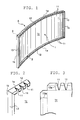
- Figs. 1 to 8 show one embodiment of the invention.
- Fig. 1 is a perspective view of the curved panel
- Fig. 2 is a perspective view of part of the panel body before it is resiliently curved
- Fig. 3 is a plan view of the part shown in Fig. 3 in unfolded condition
- Fig. 4 is a perspective, exploded view of the panel
- Fig. 5 is a transverse view of a modified form of the deformable bent marginal portion of the panel
- Fig. 6 is a perspective view of part of the panel after assemblage
- Fig. 7 is a view showing the operation of the invention
- Fig. 8 is a view showing an example of use.
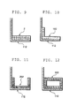
- Figs. 9 through 16 are transverse views similar to Fig. 5 but showing different embodiments of the invention.
- the curved panel A comprises a curved panel body 1 and a pair of reinforcing plates 2 fixed to the opposite sides of the panel body 1 so that the resilient force of the panel body 1 to be restored to its flat condition is balanced by the resilient force of the reinforcing plates 2 to be restored to their original shape in the opposite direction thereby to keep the panel body 1 in a desired curved condition.
- the panel body 1 is a thin steel plate, which is provided at its two opposite sides la, la with a deformable bent portion 12 having a plurality of sawtooth cuts 11, and at the other two opposite sides 1b, 1b with a reinforcing bent portion 13 without such sawtooth cuts formed therein.
- a steel plate is stamped so that along the four sides of a face plate portion lc bendable marginal portions 12a and 13a are left, which are then deformed like the letter of L in cross section by roll forming.
- the bent marginal portions 12 and 13 are connected at the four corners by welding.
- the sawtooth cuts 11 are formed in the bendable marginal portions 12a.
- the cuts 11 are V-shaped and have a bottom not pointed but rounded. Due to the arrangement, when an exterior force acts on the face portion lc of the panel body 1, the face portion 1c is comparatively easily curved along the deformable bent portions 12, but hardly along the reinforcing bent portions 13.
- the reinforcing members 2 are made of a thick steel plate cut by laser into an arcuate member having a curvature slightly greater than that of the curved surface of the panel to be manufactured.
- the reinforcing members have a cross-sectional shape substantially corresponding to that of the space defined inside the deformable bent portions 12 and a length substantially equal to that of the bent portions 12.
- the resilient force F1 of the panel body 1 to be restored to the flat condition shown in phantom line counteracts the resilient force F2 of the reinforcing member 2 to be restored to the original curvature shown in phantom line, so that the panel body 1 and the reinforcing member 2 take the intended curvature at the position shown in real line where the two forces balance.
- the processing steps required of making the illustrated embodiment is the roll forming step to form the deformable bent portions 12 and the reinforcing bent portions 13 at the two opposite sides 1a, 1a and 1b, 1b, respectively, and the cutting step by laser to form the reinforcing plates 2.
- the curved panel A is used as the front panel of a conference table B as shown in Fig. 8, it is possible to make tables of different radii, without increasing the panel size and the number of kinds of panels and consequently the manufacturing cost.
- the improved quality of the curved surface of the front panel gives a good appearance to the whole table.
- the bent portion 12 is shaped like the letter of L.
- a flange-like bent portion 112 as shown in Figs. 9, 10, 11, 12, or a bent portion 212 shaped like the letter of ⁇ as shown in Fig. 16 may also be used.
- the reinforcing members 2 are made of a thick steel plate cut to the required shape. It can also be a reinforcing angle 102 made of a steel plate bent to an L-shape in transverse section as shwon in Figs. 10, 13 and 16, or a reinforcing channel-like member 202 made of a steel plate bent to a transverse shape like the letter of ⁇ as shown in Figs.
- the reinforcing member may also be made of a shape memory alloy which is restored to a greater curvature than a desired curvature when heated to a higher temperature than the normal temperature.
- the steel plate may be a steel plate covered by venyl chroride film, a coated steel plate, a stainless steel plate, or a resiliently deformable synthetic resin plate.
- the curved panel may also be used in a desk whose front panel has a curved surface, a door or a partition wall whose whole surface is curved, an arched ceiling whose inner surface is curved, or a pillar whose outer circumference is covered with a hollow cylindrical decorative member.
- the curved panel of the invention is useful in application to a desk or a table whose front panel is curved, a door or a partition wall whose whole surface is curved, an arched ceiling whose inner surface is curved or a pillar whose outer circumference is covered with a hollow cylindrical decorative member.
Landscapes
- Engineering & Computer Science (AREA)
- Architecture (AREA)
- Civil Engineering (AREA)
- Structural Engineering (AREA)
- Bending Of Plates, Rods, And Pipes (AREA)
- Finishing Walls (AREA)
Claims (10)
- Gekrümmte Aufbautentafel mit einem Tafelkörper (1) und einer Verstärkungseinrichtung (2; 102; 202; 302), wobei der Tafelkörper (1) ein flaches Element ist, das aus einem elastisch verformbaren Material hergestellt ist, und einen Seitenabschnitt (1c) an jeder der beiden entgegengesetzten Seiten (1a), an denen ein verformbarer Kantenabschnitt (12) vorgesehen ist, der ermöglicht, daß der Seitenabschnitt gekrümmt ist, und an jeder der anderen beiden entgegengesetzten Seiten (1b), an denen ein Verstärkungskantenabschnitt (13) vorgesehen ist, der die anderen beiden entgegengesetzten Seiten des Seitenabschnittes (1c) geradlinig hält, aufweist, wobei die Verstärkungseinrichtung ein Paar Verstärkungselemente (2; 102; 202; 302) aufweist, die an dem verformbaren Kantenabschnitt (12) des Tafelkörpers (1) befestigt sind, der gezwungenermaßen gekrümmt worden ist, so daß die elastische Kraft des Tafelkörpers zum Wiedereinnehmen eines flachen Zustandes mit der elastischen Kraft der Verstärkungselemente im Gleichgewicht steht, so daß der Tafelkörper bei einer vorbestimmten Krümmung gehalten wird, die geringer als die ursprüngliche Krümmung des Verstärkungselementes ist.
- Gekrümmte Aufbautentafel gemäß Anspruch 1, wobei
jeder verformbare Kantenabschnitt (12) wie ein Flansch geformt ist und mit einer Vielzahl von Ausschnitten (11), die in Längsrichtung beabstandet sind, versehen ist. - Gekrümmte Aufbautentafel gemäß Anspruch 1, wobei
jeder verformbare Kantenabschnitt (12) L-förmig ist und mit einer Vielzahl an in Längsrichtung beabstandeten Ausschnitten (11) versehen ist. - Gekrümmte Aufbautentafel gemäß Anspruch 1, wobei
jeder verformbare Kantenabschnitt (12) U-förmig ist und mit einer Vielzahl an in Längsrichtung beabstandeten Ausschnitten (11) versehen ist. - Gekrümmte Aufbautentafel gemäß Anspruch 2 oder 3, wobei
jedes Verstärkungselement (2) eine durch ein Schneiden einer dicken Blechplatte hergestellte Verstärkungsplatte ist. - Gekrümmte Aufbautentafel gemäß Anspruch 2, 3 oder 4, wobei
jedes Verstärkungselement (102) ein Verstärkungswinkel ist, der durch ein Biegen einer Blechplatte zu einer L-Form im Querschnitt hergestellt ist. - Gekrümmte Aufbautentafel gemäß Anspruch 2 oder 3, wobei
jedes Verstärkungselement (202) ein Verstärkungskanalelement ist, das durch ein Biegen einer Blechplatte zu einer U-Form im Querschnitt hergestellt ist. - Gekrümmte Aubautentafel gemäß Anspruch 2 oder 3, wobei
jedes Verstärkungselement (302) ein Verstärkungsrohr ist, das durch ein Biegen einer Blechplatte hergestellt worden ist. - Gekrümmte Aufbautentafel gemäß Anspruch 1, wobei
jedes Verstärkungselement (2; 102; 202; 302) aus einer Formgedächtnislegierung hergestellt ist, so daß sie eine Krümmung wieder einnehmen können, die größer als eine vorbestimmte Krümmung ist. - Verfahren zum Herstellen einer gekrümmten Aufbautentafel mit den folgenden Schritten:Vorsehen eine Tafelkörpers (1) und eines Paares an Verstärkungselementen (2; 102; 202; 302), wobei der Tafelkörper (1) ein flaches Element ist, das aus einem elastisch verformbaren Material hergestellt ist und einen Seitenabschnitt (1c) aufweist,Vorsehen eines verformbaren Kantenabschnittes (12) an jeder der beiden entgegengesetzten Seiten (1a) des Seitenabschnittes (1c), wobei der verformbare Kantenabschnitt (12) ermöglicht, daß der Seitenabschnitt gekrümmt ist, und ein Verstärkungskantenabschnitt (13) an jeder der anderen beiden entgegengesetzten Seiten (1b) der Seitenabschnitte (1c) vorgesehen ist, wobei der Verstärkungskantenabschnitt (13) die anderen beiden entgegengesetzten Seiten des Seitenabschnittes (1c) geradlinig hält, undBefestigen der Verstärkungselemente an dem verformbaren Kantenabschnitt (12) des Tafelkörpers (1), der gezwungenermaßen gekrümmt worden ist, so daß die elastische Kraft des Tafelkörpers zum Wiedereinnehmen eines flachen Zustandes mit der elastischen Kraft der Verstärkungselemente in Gleichgewicht steht, so daß der Tafelkörper bei einer vorbestimmten Krümmung gehalten wird, die kleiner als die ursprüngliche Krümmung der Verstärkungselemente ist.
Applications Claiming Priority (1)
| Application Number | Priority Date | Filing Date | Title |
|---|---|---|---|
| PCT/JP1991/000001 WO1992012378A1 (fr) | 1991-01-04 | 1991-01-04 | Panneau incurve |
Publications (3)
| Publication Number | Publication Date |
|---|---|
| EP0519068A1 EP0519068A1 (de) | 1992-12-23 |
| EP0519068A4 EP0519068A4 (en) | 1993-06-02 |
| EP0519068B1 true EP0519068B1 (de) | 1999-04-28 |
Family
ID=14014206
Family Applications (1)
| Application Number | Title | Priority Date | Filing Date |
|---|---|---|---|
| EP91901638A Expired - Lifetime EP0519068B1 (de) | 1991-01-04 | 1991-01-04 | Gebogene Architekturplatte und Herstellungsverfahren |
Country Status (4)
| Country | Link |
|---|---|
| US (1) | US5384998A (de) |
| EP (1) | EP0519068B1 (de) |
| DE (1) | DE69131178T2 (de) |
| WO (1) | WO1992012378A1 (de) |
Families Citing this family (34)
| Publication number | Priority date | Publication date | Assignee | Title |
|---|---|---|---|---|
| JP3151455B2 (ja) | 1993-05-11 | 2001-04-03 | 康弘 鹿田 | 湾曲パネル |
| US5590493A (en) | 1995-07-06 | 1997-01-07 | Wilson; Jean | Wall structures for swimming pools |
| US5960596A (en) * | 1998-06-23 | 1999-10-05 | The Bilco Company | Roofing mechanism |
| TW399116B (en) | 1998-09-11 | 2000-07-21 | Hunter Douglas International | Curved building panel |
| GB2352964B (en) * | 1999-08-11 | 2004-03-10 | Kenmark Ind Co Ltd | A bendable shaping door plate device |
| NZ509371A (en) * | 2001-01-15 | 2003-07-25 | Formway Furniture Ltd | Storage unit, with door being slidable relative to framing and resiliently deformable to cover curved framing |
| US8087174B2 (en) * | 2002-01-08 | 2012-01-03 | Omnitek Partners Llc | Shape memory safety utensil |
| US20060016145A1 (en) * | 2004-07-23 | 2006-01-26 | Lonneman Deborah M | Curved ceiling panel |
| USD512787S1 (en) | 2004-09-10 | 2005-12-13 | Usg Interiors, Inc. | Curved ceiling panel |
| US8109055B2 (en) * | 2006-10-05 | 2012-02-07 | Kenneth Andrew Miller | Building panel with a rigid foam core, stud channels, and without thermal bridging |
| US8234833B2 (en) * | 2008-03-20 | 2012-08-07 | Kenneth Andrew Miller | Structural insulated roof panels with rigid foam core |
| NL2001785C2 (nl) * | 2008-07-10 | 2010-01-12 | Univ Delft Tech | Composietmateriaal omvattende een vormgeheugenpolymeer en een vormgeheugenlegering. |
| DE102008034659A1 (de) * | 2008-07-25 | 2010-02-04 | Schmidt-Seeger Gmbh | Rundbehälter zum Keimen oder Darren von Getreide |
| JP2012085937A (ja) * | 2010-10-22 | 2012-05-10 | Kokuyo Co Ltd | デスクシステム |
| USD646763S1 (en) | 2011-02-22 | 2011-10-11 | Hide A Pipe Enclosures, Inc. | Pipe enclosure |
| FR2977509B1 (fr) * | 2011-07-04 | 2014-04-25 | Mapac Panel | Dispositif de maintien pour le maintien a l'etat conforme de plaque, element de construction et procede de fabrication dudit element de construction |
| JP2012090988A (ja) * | 2011-11-15 | 2012-05-17 | Kokuyo Co Ltd | デスクシステム |
| JP2012090989A (ja) * | 2011-11-15 | 2012-05-17 | Kokuyo Co Ltd | デスクシステム |
| DE102012016044A1 (de) * | 2012-08-14 | 2014-02-20 | Jacek Synowietz | Eine selbsttragende, gebogene / gewölbte Deckenplatte ohne Unterkonstruktion aus Stahlbeton/ Holz/ Naturfasern/ Kunststoff / Metal mit Möglichkeit der Anordnung weitere Elemente wie: Vorspannung / zusätzliche Platten/ Randverstärkung. |
| US9850666B2 (en) | 2014-05-30 | 2017-12-26 | Carter Architectural Panels Inc. | Panel system for covering a building wall |
| USD767793S1 (en) | 2015-04-07 | 2016-09-27 | Carter Fabricating Inc. | Extrusion for a building panel |
| USD767382S1 (en) | 2015-04-21 | 2016-09-27 | Carter Fabricating Inc. | Building panel mid clip |
| USD767794S1 (en) | 2015-04-21 | 2016-09-27 | Carter Fabricating Inc. | Extrusion for a building panel |
| USD767381S1 (en) | 2015-04-21 | 2016-09-27 | Carter Fabricating Inc. | Building panel half clip |
| USD814256S1 (en) | 2015-10-08 | 2018-04-03 | Carter Fabricating Inc. | Panel bending tool |
| US9643228B2 (en) | 2015-10-08 | 2017-05-09 | Carter Fabricating Inc. | Panel flange bending tool |
| USD859043S1 (en) * | 2017-05-09 | 2019-09-10 | Julius Blum Gmbh | Furniture fitting part |
| USD895312S1 (en) * | 2018-05-21 | 2020-09-08 | The Boeing Company | Lateral sleep apparatus |
| US10899458B2 (en) | 2018-05-21 | 2021-01-26 | The Boeing Company | Sleep systems for aircraft |
| USD911899S1 (en) | 2018-05-21 | 2021-03-02 | The Boeing Company | Panel |
| US20220259855A1 (en) * | 2019-06-26 | 2022-08-18 | Formflow Pty Ltd | Structural member for a modular building |
| JP7808960B2 (ja) * | 2021-12-27 | 2026-01-30 | 日機装株式会社 | 封止部材およびサブマージドポンプシステム |
| FR3133060B1 (fr) * | 2022-02-25 | 2024-11-08 | Gtm Batiment | Elément de bardage métallique et procédé de rénovation utilisant un tel élément |
| USD1037498S1 (en) * | 2023-01-31 | 2024-07-30 | Advanced Drainage Systems, Inc. | Arched panel |
Family Cites Families (18)
| Publication number | Priority date | Publication date | Assignee | Title |
|---|---|---|---|---|
| US1193155A (en) * | 1916-08-01 | Gottlieb klenk | ||
| US588716A (en) * | 1897-08-24 | Watering-tank | ||
| US777950A (en) * | 1904-06-16 | 1904-12-20 | Isaac B Huenergardt | Stock-tank. |
| US832290A (en) * | 1906-04-28 | 1906-10-02 | George A Chapman | Storage-bin. |
| US1099570A (en) * | 1913-10-25 | 1914-06-09 | charles a Nicholas | Reinforcement for sheet metal and the like. |
| US1535023A (en) * | 1923-04-19 | 1925-04-21 | Carleton H Kelley | Sectional mold for concrete structures |
| US1778606A (en) * | 1929-02-16 | 1930-10-14 | Commercial Shearing | Metallic structure |
| US2197318A (en) * | 1937-04-21 | 1940-04-16 | Rumble Roy William | Adjustably curvable structural sheet |
| US2263510A (en) * | 1938-01-26 | 1941-11-18 | Harvey B Lindsay | Housing structure |
| GB628428A (en) * | 1947-09-22 | 1949-08-29 | Aluminium Plant & Vessel Co | Improvements in or relating to the construction of metal containers |
| GB791706A (en) * | 1954-10-23 | 1958-03-12 | Gabriel Renard | Panels for use as constructional units and the structures formed therefrom |
| US3947426A (en) * | 1974-04-12 | 1976-03-30 | Story Chemical Corporation | Solid particle-form polymerizable polymeric material and compositions, structures and methods of employing and producing the same |
| JPS5527397U (de) * | 1978-08-10 | 1980-02-22 | ||
| CH653369A5 (de) * | 1983-03-14 | 1985-12-31 | Bbc Brown Boveri & Cie | Verbundwerkstoff in stab-, rohr-, band-, blech- oder plattenform mit reversiblen thermo-mechanischen eigenschaften und verfahren zu dessen herstellung. |
| JPS6289413A (ja) * | 1985-10-14 | 1987-04-23 | 清水建設株式会社 | 電動式コンクリ−ト床面仕上げ機の給電方法 |
| JPH0352325Y2 (de) * | 1985-11-25 | 1991-11-13 | ||
| US4915345A (en) * | 1987-12-18 | 1990-04-10 | Symons Corporation | Concrete forming system for curved walls |
| US4978564A (en) * | 1989-04-27 | 1990-12-18 | University Of Lowell | Self-deploying structural element |
-
1991
- 1991-01-04 US US07/924,062 patent/US5384998A/en not_active Expired - Lifetime
- 1991-01-04 WO PCT/JP1991/000001 patent/WO1992012378A1/ja not_active Ceased
- 1991-01-04 EP EP91901638A patent/EP0519068B1/de not_active Expired - Lifetime
- 1991-01-04 DE DE69131178T patent/DE69131178T2/de not_active Expired - Fee Related
Also Published As
| Publication number | Publication date |
|---|---|
| DE69131178T2 (de) | 1999-12-02 |
| WO1992012378A1 (fr) | 1992-07-23 |
| EP0519068A4 (en) | 1993-06-02 |
| EP0519068A1 (de) | 1992-12-23 |
| DE69131178D1 (de) | 1999-06-02 |
| US5384998A (en) | 1995-01-31 |
Similar Documents
| Publication | Publication Date | Title |
|---|---|---|
| EP0519068B1 (de) | Gebogene Architekturplatte und Herstellungsverfahren | |
| US4757609A (en) | Apparatus for joining sheet material | |
| AU2100497A (en) | Metal panel structures | |
| US5642641A (en) | Dome shaped extruded location feature tool for making the location feature and method for locating adjoining plates using the location feature | |
| CA2147915A1 (en) | Automated dimpling apparatus | |
| CA2510698A1 (en) | Statistical tolerancing | |
| ES2016061A6 (es) | Plancha en sandwich perfeccionada y procedimiento para flexion de la misma. | |
| SE2151044A1 (en) | Processing of a two dimensional sheet material | |
| US7324868B2 (en) | Die for a press brake and method for producing the same | |
| US4768268A (en) | Method for manufacturing a single-piece type valve sleeve | |
| CN217452898U (zh) | 组装工装和谐波减速器组装系统 | |
| US5878494A (en) | Method for manufacturing a machine bearing | |
| JPWO1992012378A1 (ja) | 湾曲パネル | |
| US4309890A (en) | Method of forming a cylindrical member | |
| WO1989002179A1 (en) | Tray for cables and method of the manufacturing thereof | |
| EP0176073A2 (de) | Verfahren zum Biegen von Plattenmaterial | |
| Raucent et al. | Plastic snapfit fastener design | |
| US7926877B2 (en) | Casing for a hinge attachment of a car seat and method for its manufacturing | |
| JPS6123525A (ja) | 曲げ型 | |
| KR960007686Y1 (ko) | 홈가공용 다이 | |
| JPS63199028A (ja) | プレス型の下型 | |
| SU1123769A1 (ru) | Штамп дл обрезки полых деталей | |
| KR200311783Y1 (ko) | 가구용 절곡 판넬 | |
| Dharshan et al. | Design and analysis of a press tool for retainer used in lower door hinge of automobile | |
| JP2581610Y2 (ja) | 折曲げ加工用プレス金型 |
Legal Events
| Date | Code | Title | Description |
|---|---|---|---|
| PUAI | Public reference made under article 153(3) epc to a published international application that has entered the european phase |
Free format text: ORIGINAL CODE: 0009012 |
|
| 17P | Request for examination filed |
Effective date: 19920903 |
|
| AK | Designated contracting states |
Kind code of ref document: A1 Designated state(s): BE CH DE FR GB IT LI NL |
|
| A4 | Supplementary search report drawn up and despatched |
Effective date: 19930415 |
|
| AK | Designated contracting states |
Kind code of ref document: A4 Designated state(s): BE CH DE FR GB IT LI NL |
|
| 17Q | First examination report despatched |
Effective date: 19950505 |
|
| GRAG | Despatch of communication of intention to grant |
Free format text: ORIGINAL CODE: EPIDOS AGRA |
|
| GRAG | Despatch of communication of intention to grant |
Free format text: ORIGINAL CODE: EPIDOS AGRA |
|
| GRAH | Despatch of communication of intention to grant a patent |
Free format text: ORIGINAL CODE: EPIDOS IGRA |
|
| GRAH | Despatch of communication of intention to grant a patent |
Free format text: ORIGINAL CODE: EPIDOS IGRA |
|
| GRAA | (expected) grant |
Free format text: ORIGINAL CODE: 0009210 |
|
| AK | Designated contracting states |
Kind code of ref document: B1 Designated state(s): BE CH DE FR GB IT LI NL |
|
| REG | Reference to a national code |
Ref country code: CH Ref legal event code: EP |
|
| ITF | It: translation for a ep patent filed | ||
| REG | Reference to a national code |
Ref country code: CH Ref legal event code: NV Representative=s name: ISLER & PEDRAZZINI AG |
|
| REF | Corresponds to: |
Ref document number: 69131178 Country of ref document: DE Date of ref document: 19990602 |
|
| ET | Fr: translation filed | ||
| PLBE | No opposition filed within time limit |
Free format text: ORIGINAL CODE: 0009261 |
|
| STAA | Information on the status of an ep patent application or granted ep patent |
Free format text: STATUS: NO OPPOSITION FILED WITHIN TIME LIMIT |
|
| 26N | No opposition filed | ||
| REG | Reference to a national code |
Ref country code: GB Ref legal event code: IF02 |
|
| REG | Reference to a national code |
Ref country code: CH Ref legal event code: PCAR Free format text: ISLER & PEDRAZZINI AG;POSTFACH 1772;8027 ZUERICH (CH) |
|
| PGFP | Annual fee paid to national office [announced via postgrant information from national office to epo] |
Ref country code: CH Payment date: 20071224 Year of fee payment: 18 |
|
| PGFP | Annual fee paid to national office [announced via postgrant information from national office to epo] |
Ref country code: NL Payment date: 20080115 Year of fee payment: 18 Ref country code: DE Payment date: 20071231 Year of fee payment: 18 Ref country code: GB Payment date: 20080102 Year of fee payment: 18 Ref country code: IT Payment date: 20080128 Year of fee payment: 18 |
|
| PGFP | Annual fee paid to national office [announced via postgrant information from national office to epo] |
Ref country code: FR Payment date: 20080108 Year of fee payment: 18 |
|
| PGFP | Annual fee paid to national office [announced via postgrant information from national office to epo] |
Ref country code: BE Payment date: 20080403 Year of fee payment: 18 |
|
| REG | Reference to a national code |
Ref country code: CH Ref legal event code: PL |
|
| GBPC | Gb: european patent ceased through non-payment of renewal fee |
Effective date: 20090104 |
|
| NLV4 | Nl: lapsed or anulled due to non-payment of the annual fee |
Effective date: 20090801 |
|
| PG25 | Lapsed in a contracting state [announced via postgrant information from national office to epo] |
Ref country code: LI Free format text: LAPSE BECAUSE OF NON-PAYMENT OF DUE FEES Effective date: 20090131 Ref country code: DE Free format text: LAPSE BECAUSE OF NON-PAYMENT OF DUE FEES Effective date: 20090801 Ref country code: CH Free format text: LAPSE BECAUSE OF NON-PAYMENT OF DUE FEES Effective date: 20090131 |
|
| REG | Reference to a national code |
Ref country code: FR Ref legal event code: ST Effective date: 20091030 |
|
| PG25 | Lapsed in a contracting state [announced via postgrant information from national office to epo] |
Ref country code: GB Free format text: LAPSE BECAUSE OF NON-PAYMENT OF DUE FEES Effective date: 20090104 Ref country code: NL Free format text: LAPSE BECAUSE OF NON-PAYMENT OF DUE FEES Effective date: 20090801 |
|
| PG25 | Lapsed in a contracting state [announced via postgrant information from national office to epo] |
Ref country code: BE Free format text: LAPSE BECAUSE OF NON-PAYMENT OF DUE FEES Effective date: 20090131 |
|
| PG25 | Lapsed in a contracting state [announced via postgrant information from national office to epo] |
Ref country code: FR Free format text: LAPSE BECAUSE OF NON-PAYMENT OF DUE FEES Effective date: 20090202 |
|
| PG25 | Lapsed in a contracting state [announced via postgrant information from national office to epo] |
Ref country code: IT Free format text: LAPSE BECAUSE OF NON-PAYMENT OF DUE FEES Effective date: 20090104 |