EP0519080B1 - Filtre dielectrique - Google Patents
Filtre dielectrique Download PDFInfo
- Publication number
- EP0519080B1 EP0519080B1 EP92901463A EP92901463A EP0519080B1 EP 0519080 B1 EP0519080 B1 EP 0519080B1 EP 92901463 A EP92901463 A EP 92901463A EP 92901463 A EP92901463 A EP 92901463A EP 0519080 B1 EP0519080 B1 EP 0519080B1
- Authority
- EP
- European Patent Office
- Prior art keywords
- dielectric
- quarter
- filter
- resonators
- outer conductor
- Prior art date
- Legal status (The legal status is an assumption and is not a legal conclusion. Google has not performed a legal analysis and makes no representation as to the accuracy of the status listed.)
- Expired - Lifetime
Links
Images


Classifications
-
- H—ELECTRICITY
- H01—ELECTRIC ELEMENTS
- H01P—WAVEGUIDES; RESONATORS, LINES, OR OTHER DEVICES OF THE WAVEGUIDE TYPE
- H01P1/00—Auxiliary devices
- H01P1/20—Frequency-selective devices, e.g. filters
- H01P1/201—Filters for transverse electromagnetic waves
- H01P1/205—Comb or interdigital filters; Cascaded coaxial cavities
Definitions
- the present invention relates to a dielectric filter using a ⁇ /4 coaxial dielectric resonator and, in particular, to a dielectric filter having an attenuating pole in the neighborhood of the frequency passband in its filter frequency characteristic.
- the present invention can be applied to a low-pass filer, high-pass filter and band-pass filter in a high frequency range such as a microwave or the like.
- inductances L 1 , L 2 , etc. each disposed in series are grounded via capacitances C E1 , C E2 , C E3 , etc.
- a stray capacitance as indicated by the broken line in Fig. 2 is generated to the LC parallel connection due to the arrangement of the used coil.
- This stray capacitance is substantially difficult to remove, and has a considerable distribution.
- This distribution in turn causes a distribution of the resonant frequency of the LC parallel connection or of the impedance in the frequency passband ultimately affecting the filter frequency characteristic.
- This effect although small when the frequency is low, becomes greater if the frequency is high, thus causing the fluctuation of the attenuating pole frequency and the cut-off frequency or the increase of the mismatching loss in the frequency passband.
- any desired filter frequency characteristic cannot be obtained to make it complicated and difficult to adjust the filter frequency characteristic.
- the high-pass filter having an attenuating pole formed in the neighborhood of the cut-off frequency for achieving a steep attenuating characteristic, as shown in Fig. 4, one having an arrangement using a parallel connection of the capacitor C 1 and the coil L 1 and a parallel connection of the capacitor C 2 and the coil L 2 has been known.
- band-pass filter one having a basic arrangement as shown in Fig. 5 has been known, in which capacitances C 1 , C 2 , C 3 , C 4 , etc. and inductances L 1 , L 2 , L 3 , L 4 , etc. each alternately disposed in series are grounded via capacitances C E1 , C E2 , C E3 , etc.
- the band-pass filter having an attenuating pole formed in the neighborhood of the frequency passband for achieving a steep attenuating characteristic as shown in Fig. 6, one having an arrangement using a parallel connection of a capacitor C F1 and a coil L 1 , a parallel connection of a capacitor C F2 and a coil L 2 , a parallel connection of a capacitor C F3 and a coil L 3 , a parallel connection of a capacitor C F4 , and a coil L 4 and the like has been known.
- Such a band-pass filter also suffers from a similar problem as in the aforementioned low-pass filter or high-pass filter and, unless a considerable adjustment is made to the coil or capacitor, no desired filter frequency characteristic is obtained and, it is complicated and difficult to adjust the filter frequency characteristic.
- a ⁇ /4 coaxial dielectric resonator using a dielectric material having a high dielectric constant in order to form a band-pass filter of a high frequency range.
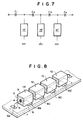
- the arrangement of a conventional band-pass filter using the dielectric resonator is illustrated in Fig. 7, in which 1A', 1B' and 1C' each denote a dielectric resonator whose outer conductor is grounded.
- 1A', 1B' and 1C' each denote a dielectric resonator whose outer conductor is grounded.
- a dielectric filter having a plurality of quarter-wavelength coaxial dielectric resonators, said resonators being each filled with a dielectric material between its inner and outer conductors, said resonators being connected in series; characterized in that the outer conductor of at least one of said quarter-wavelength coaxial dielectric resonators is grounded via a capacitance or an inductance.
- the above-described dielectric filter according to the present invention can be embodied as a filter as follows:
- a four-stage dielectric low-pass filter is shown in which four ⁇ /4 coaxial dielectric resonators 1A, 1B, 1C and 1D are used.
- the coaxial dielectric resonator is arranged so that a dielectric material 5 (for example, made of a barium titanate series substance of dielectric constant of about 93) is filled between a prismatic outer conductor 3 and a cylindrical inner conductor 4 with the outer and inner conductors 3 and 4 short-circuited at its one end surface, and it resonates when its length equals ⁇ /4 ( ⁇ denotes wavelength), as well known.
- a dielectric material 5 for example, made of a barium titanate series substance of dielectric constant of about 93
- Inner conductors 4 of the foregoing resonators 1A, 1B, 1C and 1D respectively are connected in series to each other via a lead 6.
- Each of the resonators is supported on the upper surface of a dielectric substrate 7 made of, for example, a Teflon (trademark).
- a dielectric substrate 7 made of, for example, a Teflon (trademark).
- electrode 8A of desired size connected to a lead 6 connected to the inner conductor of the resonator 1A and electrodes 8B, 8C, 8D and 8E of desired size connected to the outer conductor 3 of each resonator.
- a single grounded electrode 9 is formed opposed to the foregoing electrodes 8A through 8E.
- Capacitances C E1 , C E2 , C E3 , C E4 and C E5 are each arranged by these electrodes 8A through 8E and the grounded electrode 9.
- Fig. 10 illustrates the equivalent circuit.
- the frequency of the attenuating pole of the foregoing dielectric filter is determined by the resonant frequency of the dielectric resonator, and the frequency range and its depth ranging from the cut-off frequency up to the attenuating pole are determined by the characteristic impedance of the resonator and the capacitances C E1 through C E5 .
- Fig. 12 by way of example, illustratives a four-stage dielectric high-pass filter arranged by using four ⁇ /4 coaxial dielectric resonators 1A, 1B, 1C and 1D.
- the inner conductor 4 of the coaxial dielectric resonator is connected in series via the lead 6.
- a pattern coil 18A of desired size connected to the lead 6 connected to the inner conductor of the resonator 1A and pattern coils 18B, 18C, 18D and 18E of desired size connected to the outer conductor 3 of each resonator are formed to thereby form inductances L E1 , L E2 , L E3 , L E4 and L E5 .
- the equivalent circuit is illustrated in Fig. 13.
- the frequency of the attenuating pole of the foregoing dielectric filter is determined by the resonant frequency of the dielectric resonator, and the frequency range and its depth ranging from the cut-off frequency up to the attenuating pole are determined by the characteristic impedance of the resonator and the inductances L E1 through L E5 .
- Fig. 14 illustrates a specific example of the filter frequency characteristic according to this embodiment.
- the characteristic impedance Z O of the dielectric resonators 1A, 1B, 1C and 1D was 10 ⁇
- L E3 13 nH.
- Fig. 15 illustrates a four-stage dielectric band-pass filter arranged by using four ⁇ /4 coaxial dielectric resonators 1A, 1B, 1C and 1D.
- electrodes 27A, 27B, 27C, 27D, 27E, 28A, 28B, 28C and 28D are formed on the upper surface of the substrate 7 on which the resonator is supported. Electrodes 27B, 27C and 27D are connected to the outer conductor 3 of each resonator, and opposed to these electrodes, a single grounded electrode 9 is formed on the lower surface of the substrate 7. Capacitances C E1 , C E2 and C E3 are arranged by these electrodes 27B, 27C and 27D and the grounded electrode 9.
- electrodes 28A, 28B, 28C and 28D are each connected to the inner conductor 4 of each resonator by means of a lead, and electrodes 27A and 27E each serve as an input/output terminal.
- a pair of electrodes 27A and 28A, a pair of electrodes 27B and 28B, a pair of electrodes 27D and 28C and a pair of electrodes 27E and 28D each form capacitances C 1 , C 2 , C 3 and C 4 .
- the equivalent circuit is shown in Fig. 16.
- the frequency of the attenuating pole of the foregoing dielectric filter is determined by the resonant frequency of the dielectric resonator, and the frequency range and its depth ranging from the upper limit of the frequency passband up to the attenuating pole are determined by the characteristic impedance of the resonator and the capacitances C 1 , C 2 , C 3 , C 4 , C E1 , C E2 and C E3 .
- Fig. 17 illustrates a specific example of the filter frequency characteristic according to this embodiment.
- the characteristic impedance Z O of the dielectric resonators 1A, 1B, 1C and 1D was 7 ⁇
- C E2 5.8 pF
- the band-pass filter according to this embodiment is extremely small in insertion loss.
- Fig. 19 illustrates an example of the result obtained by the foregoing comparison.
- the characteristic impedance Z O of the dielectric resonators 1A, 1B and 1C was 8.3 ⁇
- C 2 4.1 pF
- A indicates the characteristic of the three-stage filter, B that of the four-stage filter.
- the loss value at the frequency at which the magnitude of the insertion loss becomes minimal equals 0.85 dB and, for the four-stage filter, the loss value at the frequency at which the magnitude of the insertion loss becomes minimal equals 1.20 dB, which is extremely small.
- Fig. 20 illustrates, by way of example, a four-stage dielectric band-pass filter arranged by using four ⁇ /4 coaxial dielectric resonators 1A, 1B, 1A' and 1B', in which two central stages connect the capacitances C 2 , C 3 and C 4 to the ⁇ /4 coaxial dielectric resonators 1A' and 1B' and the outer conductor of the dielectric resonator is directly grounded. That is, in this embodiment, a similar arrangement as in the conventional filter stage of Fig. 7 is used for part of the stages, in which embodiment, a useful attenuating pole can also be formed.
- the inner conductor and outer conductor of the adjacent dielectric resonators are connected via the capacitor, and the outer conductor of the dielectric resonator is grounded via the capacitors so that the attenuating pole may be available at a frequency higher than the upper limit of the frequency passband.
- coils may be used to form a band-pass filter having the attenuating pole at a frequency lower than the lower limit of the frequency passband.
- coils L 1 , L 2 , L 3 and L 4 may be connected to the dielectric resonators 1A, 1B, 1C and 1D while the outer conductor of the dielectric resonator may be grounded via coils L E1 , L E2 and L E3 so that a characteristic as shown in Fig. 23 may be achieved.
- the present invention since at least one stage is included in which the outer conductor of the ⁇ /4 coaxial dielectric resonator is grounded via the capacitances or inductances, it is possible to readily achieve a dielectric filter having the attenuating pole in the neighborhood of the frequency passband and small in insertion loss by utilizing the dielectric resonators of desired resonant frequency.
- the dielectric filter according to the present invention can be effectively used as the low-pass filter, high-pass filter and the band-pass filter in the high frequency range such as the microwave or the like.
Landscapes
- Physics & Mathematics (AREA)
- Electromagnetism (AREA)
- Control Of Motors That Do Not Use Commutators (AREA)
Abstract
Claims (12)
- Filtre diélectrique ayant une pluralité de résonateurs diélectriques coaxiaux de quart de longueur d'onde (1A, 1B, 1C, 1D), lesdits résonateurs (1A, 1B, 1C, 1D) étant chacun rempli d'un matériau diélectrique (5) entre ses conducteurs interne et externe (3, 4), lesdits résonateurs (1A, 1B, 1C, 1D) étant reliés en série ;
caractérisé en ce que
le conducteur externe (3) d'au moins un desdits résonateurs diélectriques coaxiaux de quart de longueur d'onde (1A, 1B, 1C, 1D) est relié via une capacité (CE2, CE3, CE4, CE5) ou une inductance (LE2, LE3, LE4, LE5). - Filtre diélectrique selon la revendication 1,
caractérisé en ce que ledit filtre diélectrique est adapté pour former un filtre passe-bas dans lequel ledit conducteur externe (3) dudit au moins un desdits résonateurs diélectriques coaxiaux de quart de longueur d'onde (1A, 1B, 1C, 1D) est relié à la masse via ladite capacité (CE2, CE3, CE4, CE5). - Filtre diélectrique selon la revendication 1,
caractérisé en ce que ledit filtre diélectrique est adapté pour former un filtre passe-haut dans lequel ledit conducteur externe (3) dudit au moins un desdits résonateurs diélectriques coaxiaux de quart de longueur d'onde (1A, 1B, 1C, 1D) est relié à la masse via ladite inductance (LE2, LE3, LE4, LE5). - Filtre diélectrique selon la revendication 1,
caractérisé en ce queledit filtre diélectrique est adapté pour former un filtre passe-bande dans lequel ledit conducteur externe (3) dudit au moins un desdits résonateurs diélectriques coaxiaux de quart de longueur d'onde (1A, 1B, 1C, 1D) est relié à la masse via ladite capacité (CE1, CE2, CE3) ; etdes résonateurs diélectriques coaxiaux de quart de longueur d'onde adjacents (1B, 1C) sont présents dans lequel ledit conducteur interne (4) d'un résonateur diélectrique coaxial de quart de longueur d'onde (1B, 1C) est relié audit conducteur externe (3) dudit autre résonateur diélectrique coaxial de quart de longueur d'onde (1A, 1D) via une capacité (C2, C3). - Filtre passe-bande diélectrique selon la revendication 4, caractérisé par au moins un résonateur diélectrique coaxial de quart de longueur d'onde (1A', 1B') auquel une capacité (C2, C3, C4) est reliée et dont un conducteur externe (3) est directement relié à la masse.
- Filtre diélectrique selon la revendication 1,
caractérisé en ce queledit filtre diélectrique est adapté pour former un filtre passe-bande dans lequel ledit conducteur externe (3) dudit au moins un desdits résonateurs diélectriques coaxiaux de quart de longueur d'onde (1A, 1B, 1C, 1D) est relié à la masse via ladite inductance (LE1, LE2, LE3) ; etdes résonateurs diélectriques coaxiaux de quart de longueur d'onde adjacent (1B ; 1C) sont présents dans lequel ledit conducteur interne (4) d'un résonateur diélectrique coaxial de quart de longueur d'onde (1B ; 1C) est relié audit conducteur externe (3) dudit autre résonateur diélectrique coaxial de quart de longueur d'onde (1A, 1D) via une inductance (L2, L3). - Filtre passe-bande diélectrique selon la revendication 6, caractérisé par au moins un résonateur diélectrique coaxial de quart de longueur d'onde auquel une inductance est reliée et dont un conducteur externe (3) est directement relié à la masse.
- Filtre diélectrique selon une quelconque des revendications 1 à 7, caractérisé en ce que tous lesdits résonateurs diélectriques coaxiaux de quart de longueur d'onde (1A, 1B, 1C, 1D) sont supportés sur un substrat (7).
- Filtre diélectrique selon l'une quelconque des revendications 1, 2 et 4 caractérisé en ce quetous lesdits résonateurs diélectriques coaxiaux de quart de longueur d'onde (1A, 1B, 1C, 1D) sont supportés sur une première surface d'un substrat (7) ; etladite capacité (CE2, CE3, CE4, CE5) existant sur le chemin de liaison à la masse dudit conducteur externe (3) dudit résonateur diélectrique coaxial de quart de longueur d'onde (1A, 1B, 1C, 1D) comprend une électrode (8B, 8C, 8D, 8E) formée sur ladite première surface dudit substrat (7) et une électrode reliée à la masse (9) formée sur une seconde surface dudit substrat (7).
- Filtre diélectrique selon l'une quelconque des revendications 1, 3 et 6, caractérisé en ce quetous lesdits résonateurs diélectriques coaxiaux de quart de longueur d'onde (1A, 1B, 1C, 1D) sont supportés sur une première surface d'un substrat (7) ;ladite inductance (LE2, LE3, LE4, LE5) existant sur le chemin de liaison à la masse dudit conducteur externe (3) dudit résonateur diélectrique coaxial de quart de longueur d'onde (1A, 1B, 1C, 1D) comprend une bobine en forme de motif (18B, 18C, 18D, 18E) formée sur ladite première surface dudit substrat (7) ; etune électrode reliée à la masse (9) reliée à ladite bobine en forme de motif (18B, 18C, 18D, 18E) est formée sur une seconde surface dudit substrat (7).
- Filtre diélectrique selon la revendication 4 ou 5, caractérisé en ce quetous lesdits résonateurs diélectriques coaxiaux de quart de longueur d'onde (1A, 1B, 1C, 1D) sont supportés sur une première surface d'un substrat (7) ; etladite capacité (C1, C2, C3, C4) existant à l'extérieur du chemin de liaison à la masse dudit conducteur externe (3) dudit résonateur diélectrique coaxial de quart de longueur d'onde (1A, 1B, 1C, 1D) comprend une paire d'électrodes (27A, 28A, 27B, 28B, 27D, 28C, 27E, 28D) formées sur ladite première surface dudit substrat (7).
- Filtre diélectrique selon la revendication 6 ou 7, caractérisé en ce quetous lesdits résonateurs diélectriques coaxiaux de quart de longueur d'onde (1A, 1B, 1C, 1D) sont supportés sur une première surface d'un substrat (7) ; etladite inductance (L1, L2, L3, L4) existant à l'extérieur du chemin de liaison à la masse dudit conducteur externe (3) dudit résonateur diélectrique coaxial de quart de longueur d'onde (1A, 1B, 1C, 1D) comprend une bobine en forme de motif formée sur ladite première surface dudit substrat (7).
Applications Claiming Priority (7)
| Application Number | Priority Date | Filing Date | Title |
|---|---|---|---|
| JP414043/90 | 1990-12-26 | ||
| JP2414043A JP2587880B2 (ja) | 1990-12-26 | 1990-12-26 | 誘電体ローパスフィルタ |
| JP3035645A JP2594708B2 (ja) | 1991-02-04 | 1991-02-04 | 誘電体ハイパスフィルタ |
| JP35645/91 | 1991-02-04 | ||
| JP4063591A JPH04259101A (ja) | 1991-02-13 | 1991-02-13 | 誘電体バンドパスフィルタ |
| JP40635/91 | 1991-02-13 | ||
| PCT/JP1991/001751 WO1992012546A1 (fr) | 1990-12-26 | 1991-12-24 | Filtre dielectrique |
Publications (3)
| Publication Number | Publication Date |
|---|---|
| EP0519080A1 EP0519080A1 (fr) | 1992-12-23 |
| EP0519080A4 EP0519080A4 (en) | 1993-06-09 |
| EP0519080B1 true EP0519080B1 (fr) | 1997-03-19 |
Family
ID=27288823
Family Applications (1)
| Application Number | Title | Priority Date | Filing Date |
|---|---|---|---|
| EP92901463A Expired - Lifetime EP0519080B1 (fr) | 1990-12-26 | 1991-12-24 | Filtre dielectrique |
Country Status (4)
| Country | Link |
|---|---|
| US (1) | US5493261A (fr) |
| EP (1) | EP0519080B1 (fr) |
| DE (1) | DE69125273T2 (fr) |
| WO (1) | WO1992012546A1 (fr) |
Families Citing this family (7)
| Publication number | Priority date | Publication date | Assignee | Title |
|---|---|---|---|---|
| GB2276276A (en) * | 1993-03-17 | 1994-09-21 | Marconi Gec Ltd | Coaxial resonator and multi-layer circuit board arrangement for a band stop filter |
| JPH09162766A (ja) * | 1995-12-04 | 1997-06-20 | Alps Electric Co Ltd | 衛星放送受信チューナ |
| ITMI981563A1 (it) * | 1998-07-09 | 2000-01-09 | Alsthom Cge Alcatel | Dispositivo comprendente un risonatore dielettrico coassiale montato su microstriscia a basso rumore di fase e metodo per ridurre il |
| US20020023273A1 (en) * | 2000-08-14 | 2002-02-21 | Hanmi Pharm. Co., Ltd. | Apparatus for providing a multiple internet connection service using a hybrid fiber coaxial cable network |
| JP5907124B2 (ja) * | 2013-07-24 | 2016-04-20 | 株式会社村田製作所 | 高周波部品およびフィルタ部品 |
| US10050322B2 (en) | 2014-03-24 | 2018-08-14 | Telefonaktiebolaget Lm Ericsson (Publ) | Coaxial filter and method for manufacturing the same |
| EP3163765A4 (fr) * | 2014-06-25 | 2017-07-19 | UBE Industries, Ltd. | Dispositif de transmission diélectrique sans contact et procédé de transmission sans contact |
Family Cites Families (9)
| Publication number | Priority date | Publication date | Assignee | Title |
|---|---|---|---|---|
| US4245198A (en) * | 1978-05-10 | 1981-01-13 | Murata Manufacturing Co., Ltd. | High frequency filter device |
| JPS5657304A (en) * | 1979-10-15 | 1981-05-19 | Murata Mfg Co Ltd | Branching filter using dielectric coaxial resonator |
| JPS6065601A (ja) * | 1983-09-21 | 1985-04-15 | Oki Electric Ind Co Ltd | 誘電体フィルタ |
| GB2165098B (en) * | 1984-09-27 | 1988-05-25 | Motorola Inc | Radio frequency filters |
| JPS61208902A (ja) * | 1985-03-13 | 1986-09-17 | Murata Mfg Co Ltd | Mic型誘電体フイルタ |
| JPS62128601A (ja) * | 1985-11-29 | 1987-06-10 | Murata Mfg Co Ltd | マイクロ波フイルタ |
| JPS6324703A (ja) * | 1986-07-16 | 1988-02-02 | Murata Mfg Co Ltd | フイルタ |
| JPH063842B2 (ja) * | 1987-07-31 | 1994-01-12 | 株式会社村田製作所 | マイクロ波フィルタ− |
| JPH0216802A (ja) * | 1988-07-04 | 1990-01-19 | Murata Mfg Co Ltd | バンドエリミネーションフィルタ |
-
1991
- 1991-12-24 EP EP92901463A patent/EP0519080B1/fr not_active Expired - Lifetime
- 1991-12-24 DE DE69125273T patent/DE69125273T2/de not_active Expired - Fee Related
- 1991-12-24 WO PCT/JP1991/001751 patent/WO1992012546A1/fr not_active Ceased
-
1994
- 1994-07-22 US US08/279,471 patent/US5493261A/en not_active Expired - Fee Related
Also Published As
| Publication number | Publication date |
|---|---|
| WO1992012546A1 (fr) | 1992-07-23 |
| DE69125273T2 (de) | 1997-08-28 |
| DE69125273D1 (de) | 1997-04-24 |
| EP0519080A1 (fr) | 1992-12-23 |
| EP0519080A4 (en) | 1993-06-09 |
| US5493261A (en) | 1996-02-20 |
Similar Documents
| Publication | Publication Date | Title |
|---|---|---|
| US5227748A (en) | Filter with electrically adjustable attenuation characteristic | |
| US3879690A (en) | Distributed transmission line filter | |
| US5293141A (en) | Dielectric filter having external connection terminals on dielectric substrate and antenna duplexer using the same | |
| US5416454A (en) | Stripline filter with a high side transmission zero | |
| US6686815B1 (en) | Microwave filter | |
| US5066933A (en) | Band-pass filter | |
| US5812036A (en) | Dielectric filter having intrinsic inter-resonator coupling | |
| US7116188B2 (en) | Laminated dielectric filter, and antenna duplexer and communication equipment using the same | |
| JP3344428B2 (ja) | 誘電体共振器および誘電体共振部品 | |
| CA2089155C (fr) | Filtre coupe-bande ceramique monolithique multi-etage a etages de filtrage isoles | |
| US6720849B2 (en) | High frequency filter, filter device, and electronic apparatus incorporating the same | |
| US4837534A (en) | Ceramic block filter with bidirectional tuning | |
| EP0519080B1 (fr) | Filtre dielectrique | |
| US5187459A (en) | Compact coupled line filter circuit | |
| JPH0369202B2 (fr) | ||
| EP0576273B1 (fr) | Résonateur coaxial et filtre diélectrique l'utilisant | |
| US6525625B1 (en) | Dielectric duplexer and communication apparatus | |
| JP3050090B2 (ja) | 誘電体フィルタ | |
| RU2222076C2 (ru) | Микрополосковый полосно-пропускающий фильтр с широкой полосой заграждения | |
| JPH03252201A (ja) | 帯域減衰フィルタ | |
| KR100501928B1 (ko) | 커패시터가 로딩된 다중층 1/4 파장 공진기를 이용한 이단 적층 대역통과 여파기 | |
| JPS6138885B2 (fr) | ||
| JP2005150927A (ja) | 誘電体フィルタ、誘電体デュプレクサおよび通信装置 | |
| KR100314087B1 (ko) | 세라믹 필터 | |
| JPS633209Y2 (fr) |
Legal Events
| Date | Code | Title | Description |
|---|---|---|---|
| PUAI | Public reference made under article 153(3) epc to a published international application that has entered the european phase |
Free format text: ORIGINAL CODE: 0009012 |
|
| 17P | Request for examination filed |
Effective date: 19920825 |
|
| AK | Designated contracting states |
Kind code of ref document: A1 Designated state(s): DE FR GB IT |
|
| A4 | Supplementary search report drawn up and despatched |
Effective date: 19930421 |
|
| AK | Designated contracting states |
Kind code of ref document: A4 Designated state(s): DE FR GB IT |
|
| 17Q | First examination report despatched |
Effective date: 19950403 |
|
| GRAG | Despatch of communication of intention to grant |
Free format text: ORIGINAL CODE: EPIDOS AGRA |
|
| GRAH | Despatch of communication of intention to grant a patent |
Free format text: ORIGINAL CODE: EPIDOS IGRA |
|
| GRAH | Despatch of communication of intention to grant a patent |
Free format text: ORIGINAL CODE: EPIDOS IGRA |
|
| GRAA | (expected) grant |
Free format text: ORIGINAL CODE: 0009210 |
|
| AK | Designated contracting states |
Kind code of ref document: B1 Designated state(s): DE FR GB IT |
|
| PG25 | Lapsed in a contracting state [announced via postgrant information from national office to epo] |
Ref country code: IT Free format text: LAPSE BECAUSE OF FAILURE TO SUBMIT A TRANSLATION OF THE DESCRIPTION OR TO PAY THE FEE WITHIN THE PRE;WARNING: LAPSES OF ITALIAN PATENTS WITH EFFECTIVE DATE BEFORE 2007 MAY HAVE OCCURRED AT ANY TIME BEFORE 2007. THE CORRECT EFFECTIVE DATE MAY BE DIFFERENT FROM THE ONE RECORDED.SCRIBED TIME-LIMIT Effective date: 19970319 |
|
| REF | Corresponds to: |
Ref document number: 69125273 Country of ref document: DE Date of ref document: 19970424 |
|
| ET | Fr: translation filed | ||
| PLBE | No opposition filed within time limit |
Free format text: ORIGINAL CODE: 0009261 |
|
| STAA | Information on the status of an ep patent application or granted ep patent |
Free format text: STATUS: NO OPPOSITION FILED WITHIN TIME LIMIT |
|
| 26N | No opposition filed | ||
| REG | Reference to a national code |
Ref country code: GB Ref legal event code: IF02 |
|
| PGFP | Annual fee paid to national office [announced via postgrant information from national office to epo] |
Ref country code: GB Payment date: 20041214 Year of fee payment: 14 |
|
| PGFP | Annual fee paid to national office [announced via postgrant information from national office to epo] |
Ref country code: FR Payment date: 20041221 Year of fee payment: 14 |
|
| PGFP | Annual fee paid to national office [announced via postgrant information from national office to epo] |
Ref country code: DE Payment date: 20050131 Year of fee payment: 14 |
|
| PG25 | Lapsed in a contracting state [announced via postgrant information from national office to epo] |
Ref country code: GB Free format text: LAPSE BECAUSE OF NON-PAYMENT OF DUE FEES Effective date: 20051224 |
|
| PG25 | Lapsed in a contracting state [announced via postgrant information from national office to epo] |
Ref country code: DE Free format text: LAPSE BECAUSE OF NON-PAYMENT OF DUE FEES Effective date: 20060701 |
|
| GBPC | Gb: european patent ceased through non-payment of renewal fee |
Effective date: 20051224 |
|
| PG25 | Lapsed in a contracting state [announced via postgrant information from national office to epo] |
Ref country code: FR Free format text: LAPSE BECAUSE OF NON-PAYMENT OF DUE FEES Effective date: 20060831 |
|
| REG | Reference to a national code |
Ref country code: FR Ref legal event code: ST Effective date: 20060831 |