EP0519112B1 - Reflektor und Verfahren zum Erzeugen einer Reflektorform - Google Patents
Reflektor und Verfahren zum Erzeugen einer Reflektorform Download PDFInfo
- Publication number
- EP0519112B1 EP0519112B1 EP91110286A EP91110286A EP0519112B1 EP 0519112 B1 EP0519112 B1 EP 0519112B1 EP 91110286 A EP91110286 A EP 91110286A EP 91110286 A EP91110286 A EP 91110286A EP 0519112 B1 EP0519112 B1 EP 0519112B1
- Authority
- EP
- European Patent Office
- Prior art keywords
- reflector
- segments
- curve
- conic
- intersection
- Prior art date
- Legal status (The legal status is an assumption and is not a legal conclusion. Google has not performed a legal analysis and makes no representation as to the accuracy of the status listed.)
- Expired - Lifetime
Links
- 238000000034 method Methods 0.000 title claims description 13
- 230000005855 radiation Effects 0.000 claims description 50
- 238000009826 distribution Methods 0.000 claims description 42
- 230000003287 optical effect Effects 0.000 claims description 14
- 238000005304 joining Methods 0.000 claims description 4
- 238000010276 construction Methods 0.000 description 12
- 230000007704 transition Effects 0.000 description 7
- 238000004519 manufacturing process Methods 0.000 description 6
- 238000012986 modification Methods 0.000 description 6
- 230000004048 modification Effects 0.000 description 6
- 230000008859 change Effects 0.000 description 5
- 238000006073 displacement reaction Methods 0.000 description 4
- 230000004313 glare Effects 0.000 description 4
- 229920001817 Agar Polymers 0.000 description 3
- 230000008901 benefit Effects 0.000 description 3
- 241001523162 Helle Species 0.000 description 2
- 238000013459 approach Methods 0.000 description 2
- 238000004364 calculation method Methods 0.000 description 2
- 238000013461 design Methods 0.000 description 2
- 230000006872 improvement Effects 0.000 description 2
- 238000002686 lithotriptor Methods 0.000 description 2
- 230000035939 shock Effects 0.000 description 2
- 240000003380 Passiflora rubra Species 0.000 description 1
- 230000015556 catabolic process Effects 0.000 description 1
- 238000005520 cutting process Methods 0.000 description 1
- 230000001419 dependent effect Effects 0.000 description 1
- 238000011161 development Methods 0.000 description 1
- 230000005670 electromagnetic radiation Effects 0.000 description 1
- 238000005516 engineering process Methods 0.000 description 1
- 238000002474 experimental method Methods 0.000 description 1
- 238000005286 illumination Methods 0.000 description 1
- 238000011835 investigation Methods 0.000 description 1
- 238000007620 mathematical function Methods 0.000 description 1
- 238000005488 sandblasting Methods 0.000 description 1
- 230000003595 spectral effect Effects 0.000 description 1
- 239000004575 stone Substances 0.000 description 1
Images


Classifications
-
- G—PHYSICS
- G02—OPTICS
- G02B—OPTICAL ELEMENTS, SYSTEMS OR APPARATUS
- G02B5/00—Optical elements other than lenses
- G02B5/08—Mirrors
- G02B5/10—Mirrors with curved faces
-
- F—MECHANICAL ENGINEERING; LIGHTING; HEATING; WEAPONS; BLASTING
- F21—LIGHTING
- F21S—NON-PORTABLE LIGHTING DEVICES; SYSTEMS THEREOF; VEHICLE LIGHTING DEVICES SPECIALLY ADAPTED FOR VEHICLE EXTERIORS
- F21S41/00—Illuminating devices specially adapted for vehicle exteriors, e.g. headlamps
- F21S41/30—Illuminating devices specially adapted for vehicle exteriors, e.g. headlamps characterised by reflectors
- F21S41/32—Optical layout thereof
- F21S41/33—Multi-surface reflectors, e.g. reflectors with facets or reflectors with portions of different curvature
- F21S41/331—Multi-surface reflectors, e.g. reflectors with facets or reflectors with portions of different curvature the reflector consisting of complete annular areas
- F21S41/332—Multi-surface reflectors, e.g. reflectors with facets or reflectors with portions of different curvature the reflector consisting of complete annular areas with continuity at the junction between adjacent areas
-
- Y—GENERAL TAGGING OF NEW TECHNOLOGICAL DEVELOPMENTS; GENERAL TAGGING OF CROSS-SECTIONAL TECHNOLOGIES SPANNING OVER SEVERAL SECTIONS OF THE IPC; TECHNICAL SUBJECTS COVERED BY FORMER USPC CROSS-REFERENCE ART COLLECTIONS [XRACs] AND DIGESTS
- Y10—TECHNICAL SUBJECTS COVERED BY FORMER USPC
- Y10S—TECHNICAL SUBJECTS COVERED BY FORMER USPC CROSS-REFERENCE ART COLLECTIONS [XRACs] AND DIGESTS
- Y10S359/00—Optical: systems and elements
- Y10S359/90—Methods
Definitions
- the invention relates to a reflector for radiation emanating from a radiation source with a shape such that a reflector intersection curve in a plane containing an axis of the reflector and the radiation source has segments of different curved cone sections, that is to say lines that have not degenerated into straight lines, which merge into one another without edges, the cone section segments are directly joined together. Furthermore, the invention also relates to a method for producing reflector shapes.
- the reflectors in question have a wide variety of tasks. For example, it may be desirable to achieve a high energy density at a desired distance from the reflector, or a homogeneous energy distribution at a certain distance from the reflector or an exact phase adjustment may also be desired.
- radiation-directing elements such as lenses or the like
- the imperfection of the reflector shape with regard to the direction and distribution of the radiation is overcome by additional components.
- the invention relates to the design of reflector shapes using a computer.
- radiation distributions generated using a specific reflector shape can be calculated in advance using a computer.
- computers are also already used to form reflector shapes to determine.
- the computer calculations are based on conic sections and are therefore severely restricted.
- the invention shows new reflector shapes that can be determined by means of a computer.
- US-A-4 984 140 describes a reflector formed from a section of a paraboloid of revolution and a cone section, these areas being smoothly joined together.
- a reflector is disclosed which has two parabolic sections with a smoothly adjoining conical section located between them.
- EP-A-0 307 657 describes a headlight for vehicles, the reflector of which is composed of four segments of different shapes. The individual segments should merge seamlessly. The document does not teach how such a reflector with a stepless transition can be constructed without deviating from exact conical shapes.
- EP-A-0 402 740 (the inventor of the present application) teaches a method for producing different reflector shapes that are not conic curves.
- the reflector cut curves in these known reflector shapes meet the above three criteria and thus enable the construction of a reflector whose light distribution can be determined in advance and which therefore does not require an experiment to exactly determine the radiation distribution.
- a reflector according to the invention for solving this problem is characterized in that at the point of contact of two adjoining conic section segments, the tangents which can be applied to both conic section segments are the same and that the first focal points of the conic section segments fall apart.
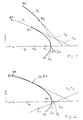
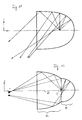
- the piece A1 to B2 of the parabola P1 should therefore be replaced by another conic section, namely the segment A2 to B2 of the parabola P2.
- the tangents T1 at point A1 at parabola P1 and T2 at point A2 at parabola P2 are determined.
- the tangents T1, T2 each intersect the axis A at a certain angle.
- the tangents are brought into parallel position.
- segment A2-B2 of parabola P2 is rotated around point A2 until tangent T2 runs parallel to tangent T1.
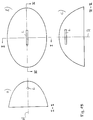
- segment A2-B2 is shifted in parallel so that point A2 coincides with point A1. This is shown in Fig.2.
- the segments S1-A1 and A2-B2, each shown with a solid line, are now directly adjacent to one another, ie there is no transition piece between the conic sections.
- the result is a reflector intersection curve S1-A1 / A2-B2 (shown in Fig. 2 with a solid line), which consist entirely of conic section segments from different conic sections and which continuously merge into one another, i.e. at the contact point A1, A2 are from both directions equal tangents.
- the radiation distribution of a reflector formed according to the reflector section curve of FIG. 2 can be determined completely, since the tangent and thus the angle of incidence and angle of incidence of a beam are known for each point on the reflector surface.
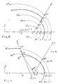
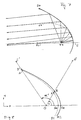
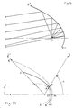
- the polar beam 0-S intersects the parabolas at points A1, A2, A3, A4 and A5, whereby the tangents applied to the parabolas in these points are all parallel.
- the segment A4-B4 only needs to be shifted in parallel so that point A4 on the polar beam 0-S is transferred to point A3, which is shown in FIG. 4 is indicated by an arrow.
- the tangents are identical as desired.
Landscapes
- Physics & Mathematics (AREA)
- General Physics & Mathematics (AREA)
- Optics & Photonics (AREA)
- Engineering & Computer Science (AREA)
- General Engineering & Computer Science (AREA)
- Optical Elements Other Than Lenses (AREA)
Priority Applications (4)
| Application Number | Priority Date | Filing Date | Title |
|---|---|---|---|
| EP91110286A EP0519112B1 (de) | 1991-06-21 | 1991-06-21 | Reflektor und Verfahren zum Erzeugen einer Reflektorform |
| DE59107556T DE59107556D1 (de) | 1991-06-21 | 1991-06-21 | Reflektor und Verfahren zum Erzeugen einer Reflektorform |
| US07/896,194 US5408363A (en) | 1991-06-21 | 1992-06-10 | Reflector and a method of generating a reflector shape |
| JP4161037A JPH0793045B2 (ja) | 1991-06-21 | 1992-06-19 | レフレクタ−及びレフレクタ−用断面曲線の設計方法 |
Applications Claiming Priority (1)
| Application Number | Priority Date | Filing Date | Title |
|---|---|---|---|
| EP91110286A EP0519112B1 (de) | 1991-06-21 | 1991-06-21 | Reflektor und Verfahren zum Erzeugen einer Reflektorform |
Publications (2)
| Publication Number | Publication Date |
|---|---|
| EP0519112A1 EP0519112A1 (de) | 1992-12-23 |
| EP0519112B1 true EP0519112B1 (de) | 1996-03-13 |
Family
ID=8206862
Family Applications (1)
| Application Number | Title | Priority Date | Filing Date |
|---|---|---|---|
| EP91110286A Expired - Lifetime EP0519112B1 (de) | 1991-06-21 | 1991-06-21 | Reflektor und Verfahren zum Erzeugen einer Reflektorform |
Country Status (4)
| Country | Link |
|---|---|
| US (1) | US5408363A (ja) |
| EP (1) | EP0519112B1 (ja) |
| JP (1) | JPH0793045B2 (ja) |
| DE (1) | DE59107556D1 (ja) |
Families Citing this family (35)
| Publication number | Priority date | Publication date | Assignee | Title |
|---|---|---|---|---|
| DE69521371T2 (de) * | 1994-03-10 | 2002-05-02 | Koninklijke Philips Electronics N.V., Eindhoven | Elektrische reflektorlampe |
| JP3185126B2 (ja) * | 1994-10-28 | 2001-07-09 | 株式会社小糸製作所 | 車輌用灯具の反射鏡及びその形成方法 |
| JP3185125B2 (ja) * | 1994-10-28 | 2001-07-09 | 株式会社小糸製作所 | 車輌用灯具の反射鏡及びその形成方法 |
| JP3187293B2 (ja) * | 1995-07-17 | 2001-07-11 | 株式会社小糸製作所 | 車輌用灯具の反射鏡の反射面形成方法 |
| WO1997018551A1 (es) * | 1995-11-15 | 1997-05-22 | Universidad Nacional Autonoma De Mexico | Reflectores multifocales compuestos para concentrar ondas de choque |
| US5934779A (en) * | 1996-07-26 | 1999-08-10 | Eastman Kodak Company | Reflector and a reflector/light source system |
| US5961196A (en) * | 1996-07-26 | 1999-10-05 | Eastman Kodak Company | Flash device for dye transferring |
| US6007220A (en) * | 1996-11-13 | 1999-12-28 | Innovative Engineering Solutions, Inc | Reflectors for fluorescent light fixtures |
| ITTO970059A1 (it) * | 1997-01-27 | 1998-07-27 | Fiat Ricerche | Riflettore per dispositivo di illuminazione con sorgente luminosa este sa. |
| JPH10268449A (ja) * | 1997-03-24 | 1998-10-09 | Fuji Photo Optical Co Ltd | 照明光学系およびこの光学系を用いた投射光学系 |
| US5913599A (en) * | 1997-06-11 | 1999-06-22 | Steris Corporation | Surgical light with conical reflector |
| JP4011221B2 (ja) * | 1999-01-21 | 2007-11-21 | 株式会社小糸製作所 | 車両用標識灯 |
| JP3424915B2 (ja) * | 1999-04-06 | 2003-07-07 | スタンレー電気株式会社 | 反射鏡の製造方法および灯具 |
| DE19940207B4 (de) * | 1999-08-25 | 2005-07-14 | Tetsuhiro Kano | Reflektorsystem zum Führen von Licht unter kleinen Einfallswinkeln |
| JP4563557B2 (ja) * | 2000-07-18 | 2010-10-13 | 株式会社トプコン | 露光装置の照明光学系 |
| USD438135S1 (en) | 2000-07-28 | 2001-02-27 | Accu-Sort Systems, Inc. | Varying elliptical reflector |
| US6967283B2 (en) | 2001-03-20 | 2005-11-22 | American Power Conversion Corporation | Adjustable scalable rack power system and method |
| US6705737B1 (en) * | 2002-08-20 | 2004-03-16 | Raytheon Co. | Reflective optical apparatus for interconverting between a point of light and a line of light |
| US7034320B2 (en) * | 2003-03-20 | 2006-04-25 | Intel Corporation | Dual hemispherical collectors |
| EP1753996B1 (en) * | 2004-03-30 | 2011-06-29 | Illumination Management Solutions, Inc. | An apparatus and method for improved illumination area fill |
| US20080030982A1 (en) * | 2006-08-04 | 2008-02-07 | Vode Llc | Modular lighting system |
| DE102009013812A1 (de) | 2009-03-18 | 2010-09-23 | Osram Gesellschaft mit beschränkter Haftung | Reflektor, Lichtquellenanordnung sowie Projektorgerät |
| DK3117784T3 (en) | 2009-07-08 | 2019-04-08 | Sanuwave Inc | USE OF INTRACORPORAL PRESSURE SHOCK WAVES IN MEDICINE |
| CN101900296B (zh) * | 2010-08-30 | 2012-06-27 | 珠海晟源同泰电子有限公司 | 匀光聚束反光器的设计方法 |
| US9791690B2 (en) | 2012-05-29 | 2017-10-17 | Siemens Healthcare Diagnostics Inc. | Shutter assembly for a luminescence-based sample analyzer |
| WO2014152845A1 (en) * | 2013-03-20 | 2014-09-25 | Siemens Healthcare Diagnostics Inc. | Light and shutter for a sample analyzer |
| CN105526557A (zh) * | 2014-10-23 | 2016-04-27 | 北京航天长征飞行器研究所 | 一种用于阳极倒置的氙灯的聚光镜 |
| DE102014117453A1 (de) * | 2014-11-27 | 2016-06-02 | Carl Zeiss Smt Gmbh | Kollektorspiegel für Mikrolithografie |
| US10808896B2 (en) | 2014-12-31 | 2020-10-20 | Aron Lighting LLC | T-bar lighting assembly |
| KR102583380B1 (ko) | 2017-01-17 | 2023-10-04 | 솔리톤, 인코포레이티드 | 개선된 음향 파면을 갖는 급속 펄스 전기유압식(eh) 충격파 발생기 장치 |
| US10859242B2 (en) | 2018-02-07 | 2020-12-08 | Aron Lighting LLC | Downlight for ceiling system |
| USD921266S1 (en) | 2018-11-16 | 2021-06-01 | Aron Lighting LLC | Lighting fixture in a ceiling tile arrangement |
| US11543092B2 (en) | 2020-06-08 | 2023-01-03 | Aron Lighting LLC | Ceiling mounted assembly for electrical components |
| CN114966706B (zh) * | 2022-04-14 | 2022-12-20 | 西安定华电子股份有限公司 | 确定方法、系统、反射器、立罐外测液位计及其安装方法 |
| DE102022211866A1 (de) * | 2022-11-09 | 2024-05-16 | Carl Zeiss Smt Gmbh | Spiegelelement, Lithographiesystem und Verfahren zur Bereitstellung eines Spiegelelements |
Citations (1)
| Publication number | Priority date | Publication date | Assignee | Title |
|---|---|---|---|---|
| EP0307657A2 (de) * | 1987-09-17 | 1989-03-22 | Robert Bosch Gmbh | Abblendlicht-Scheinwerfer |
Family Cites Families (19)
| Publication number | Priority date | Publication date | Assignee | Title |
|---|---|---|---|---|
| DE159809C (ja) * | ||||
| US2819404A (en) * | 1951-05-25 | 1958-01-07 | Herrnring Gunther | Optical image-forming mirror systems having aspherical reflecting surfaces |
| US2759106A (en) * | 1951-05-25 | 1956-08-14 | Wolter Hans | Optical image-forming mirror system providing for grazing incidence of rays |
| US3443086A (en) * | 1967-05-16 | 1969-05-06 | Giannini Scient Corp | Beam-forming system |
| CH526071A (fr) * | 1968-08-21 | 1972-07-31 | Leon Perret Samuel | Réflecteur de projection et de réception de radiations |
| GB2079435B (en) * | 1980-07-03 | 1984-05-23 | Gen Electric | Reflector lamp |
| DD159809A1 (de) * | 1981-06-19 | 1983-04-06 | Reinhard Goerke | Leuchte mit asymmetrischen reflektor |
| NL8105535A (nl) * | 1981-12-09 | 1983-07-01 | Philips Nv | Reflektor. |
| JPS5940403A (ja) * | 1982-08-27 | 1984-03-06 | 三菱電機株式会社 | 投光器 |
| US4557569A (en) * | 1983-11-17 | 1985-12-10 | The United States Of America As Represented By The Secretary Of The Army | Distended point source reflector having conical sections |
| JPS60184250A (ja) * | 1984-03-01 | 1985-09-19 | フュージョン・システムズ・コーポレーション | セグメント化された反射器を有するランプ |
| JP2622564B2 (ja) * | 1986-12-30 | 1997-06-18 | ヴァレオ ヴイジョン | カットオフによって限定されたビームを放射する、変形底部を有する自動車用前照灯 |
| FR2623633B1 (fr) * | 1987-11-25 | 1991-08-16 | Armines | Appareil emetteur de rayonnement infrarouge comportant au moins une source cylindrique de rayons infrarouges et un reflecteur |
| DE68917198T2 (de) * | 1988-05-09 | 1994-11-17 | Ichiko Industries Ltd | Scheinwerfer für Kraftfahrzeuge. |
| FR2634003B1 (fr) * | 1988-07-05 | 1991-05-24 | Cibie Projecteurs | Projecteur de vehicule automobile a reflecteur multi-zones et procede de lissage d'un tel reflecteur |
| JPH0810561B2 (ja) * | 1988-11-30 | 1996-01-31 | 市光工業株式会社 | 前照灯の光学系 |
| JP2508827B2 (ja) * | 1988-11-30 | 1996-06-19 | 市光工業株式会社 | 自動車用前照灯 |
| DE3919334A1 (de) * | 1989-06-13 | 1990-12-20 | Tetsuhiro Kano | Reflektor fuer eine leuchte |
| US4984140A (en) * | 1989-07-19 | 1991-01-08 | Ellion M Edmund | Hand held flashlight with selective beam and enhanced apparent brightness |
-
1991
- 1991-06-21 EP EP91110286A patent/EP0519112B1/de not_active Expired - Lifetime
- 1991-06-21 DE DE59107556T patent/DE59107556D1/de not_active Expired - Lifetime
-
1992
- 1992-06-10 US US07/896,194 patent/US5408363A/en not_active Expired - Fee Related
- 1992-06-19 JP JP4161037A patent/JPH0793045B2/ja not_active Expired - Fee Related
Patent Citations (1)
| Publication number | Priority date | Publication date | Assignee | Title |
|---|---|---|---|---|
| EP0307657A2 (de) * | 1987-09-17 | 1989-03-22 | Robert Bosch Gmbh | Abblendlicht-Scheinwerfer |
Also Published As
| Publication number | Publication date |
|---|---|
| JPH06119805A (ja) | 1994-04-28 |
| DE59107556D1 (de) | 1996-04-18 |
| US5408363A (en) | 1995-04-18 |
| EP0519112A1 (de) | 1992-12-23 |
| JPH0793045B2 (ja) | 1995-10-09 |
Similar Documents
| Publication | Publication Date | Title |
|---|---|---|
| EP0519112B1 (de) | Reflektor und Verfahren zum Erzeugen einer Reflektorform | |
| DE3027719C2 (ja) | ||
| EP0402740B2 (de) | Verfahren zum Bestimmen der Form eines Reflektors | |
| DE3024040C2 (ja) | ||
| DE19804960A1 (de) | Kraftfahrzeugscheinwerfer mit einem Spiegel mit seitlich nebeneinander angeordneten Zonen und Verfahren zur Herstellung eines solchen Spiegels | |
| DE69112312T2 (de) | Reflektor für eine Beleuchtungsvorrichtung eines Fahrzeuges und Scheinwerfer und Signalleuchte mit solchem Reflektor. | |
| DE69130738T2 (de) | Reflektor mit lampe | |
| DE2333181A1 (de) | Spiegelsystem zur sammlung optischer strahlungsenergie einer mehrzahl von strahlungsquellen | |
| DE3341773A1 (de) | Abblendlichtscheinwerfer fuer kraftfahrzeuge | |
| DE2826867A1 (de) | Leuchte | |
| DE4300103A1 (ja) | ||
| EP3575674B1 (de) | Lichtleiter für eine kraftfahrzeugbeleuchtungseinrichtung | |
| DE19630409B4 (de) | Fahrzeugleuchte mit einem Reflektor mit einer Reflexionsstufen aufweisenden Reflexionsfläche | |
| DE69937917T2 (de) | Kfz-Scheinwerfer mit einer querliegenden Lichtquelle und zum Erzeugen von einer scharfen Lichtbegrenzung | |
| DE102011115756B4 (de) | Scheinwerfer | |
| DE68917176T2 (de) | Scheinwerfer für Fahrzeuge. | |
| DE2921068A1 (de) | Fahrzeugscheinwerfer | |
| DE19805217B4 (de) | Kraftfahrzeugscheinwerfer mit einem Spiegel mit seitlich nebeneinander angeordneten Zonen und Verfahren zur Herstellung eines solchen Spiegels | |
| DE10048142B4 (de) | Verfahren zur Festlegung der reflektierenden Oberfläche eines Reflektors in einer Fahrzeugleuchte | |
| DE4329850C2 (de) | Reflektor für einen Fahrzeugscheinwerfer | |
| DE2923316A1 (de) | Kraftfahrzeug-scheinwerfer mit gerippter lichtablenkglasscheibe | |
| DE2147371A1 (de) | Facettenreflektor und Verfahren zu seiner Herstellung | |
| DE2205610C3 (de) | Abblendbarer Fahrzeugscheinwerfer | |
| EP0422084B1 (de) | Leuchte, insbesondere für kraftfahrzeuge | |
| DE10161935A1 (de) | Verfahren zum Entwerfen einer reflektierenden Oberfläche eines Reflektors in einer Fahrzeugleuchte |
Legal Events
| Date | Code | Title | Description |
|---|---|---|---|
| PUAI | Public reference made under article 153(3) epc to a published international application that has entered the european phase |
Free format text: ORIGINAL CODE: 0009012 |
|
| 17P | Request for examination filed |
Effective date: 19910621 |
|
| AK | Designated contracting states |
Kind code of ref document: A1 Designated state(s): AT BE CH DE DK ES FR GB IT LI NL SE |
|
| 17Q | First examination report despatched |
Effective date: 19940405 |
|
| RBV | Designated contracting states (corrected) |
Designated state(s): DE FR GB IT NL |
|
| GRAA | (expected) grant |
Free format text: ORIGINAL CODE: 0009210 |
|
| AK | Designated contracting states |
Kind code of ref document: B1 Designated state(s): DE FR GB IT NL |
|
| GBT | Gb: translation of ep patent filed (gb section 77(6)(a)/1977) |
Effective date: 19960313 |
|
| ITF | It: translation for a ep patent filed | ||
| REF | Corresponds to: |
Ref document number: 59107556 Country of ref document: DE Date of ref document: 19960418 |
|
| ET | Fr: translation filed | ||
| PLBE | No opposition filed within time limit |
Free format text: ORIGINAL CODE: 0009261 |
|
| STAA | Information on the status of an ep patent application or granted ep patent |
Free format text: STATUS: NO OPPOSITION FILED WITHIN TIME LIMIT |
|
| 26N | No opposition filed | ||
| REG | Reference to a national code |
Ref country code: GB Ref legal event code: IF02 |
|
| PGFP | Annual fee paid to national office [announced via postgrant information from national office to epo] |
Ref country code: NL Payment date: 20060619 Year of fee payment: 16 |
|
| PGFP | Annual fee paid to national office [announced via postgrant information from national office to epo] |
Ref country code: GB Payment date: 20070524 Year of fee payment: 17 |
|
| PGFP | Annual fee paid to national office [announced via postgrant information from national office to epo] |
Ref country code: IT Payment date: 20070627 Year of fee payment: 17 |
|
| NLV4 | Nl: lapsed or anulled due to non-payment of the annual fee |
Effective date: 20080101 |
|
| PG25 | Lapsed in a contracting state [announced via postgrant information from national office to epo] |
Ref country code: NL Free format text: LAPSE BECAUSE OF NON-PAYMENT OF DUE FEES Effective date: 20080101 |
|
| PGFP | Annual fee paid to national office [announced via postgrant information from national office to epo] |
Ref country code: FR Payment date: 20070524 Year of fee payment: 17 |
|
| GBPC | Gb: european patent ceased through non-payment of renewal fee |
Effective date: 20080621 |
|
| REG | Reference to a national code |
Ref country code: FR Ref legal event code: ST Effective date: 20090228 |
|
| PG25 | Lapsed in a contracting state [announced via postgrant information from national office to epo] |
Ref country code: GB Free format text: LAPSE BECAUSE OF NON-PAYMENT OF DUE FEES Effective date: 20080621 |
|
| PG25 | Lapsed in a contracting state [announced via postgrant information from national office to epo] |
Ref country code: FR Free format text: LAPSE BECAUSE OF NON-PAYMENT OF DUE FEES Effective date: 20080630 Ref country code: IT Free format text: LAPSE BECAUSE OF NON-PAYMENT OF DUE FEES Effective date: 20080621 |
|
| PGFP | Annual fee paid to national office [announced via postgrant information from national office to epo] |
Ref country code: DE Payment date: 20100628 Year of fee payment: 20 |
|
| REG | Reference to a national code |
Ref country code: DE Ref legal event code: R071 Ref document number: 59107556 Country of ref document: DE |
|
| REG | Reference to a national code |
Ref country code: DE Ref legal event code: R071 Ref document number: 59107556 Country of ref document: DE |
|
| PG25 | Lapsed in a contracting state [announced via postgrant information from national office to epo] |
Ref country code: DE Free format text: LAPSE BECAUSE OF EXPIRATION OF PROTECTION Effective date: 20110622 |