EP0519308A2 - Cavité résonnante pour hyperfréquences avec double résonateur diélectrique et fréquence de résonance réglable - Google Patents
Cavité résonnante pour hyperfréquences avec double résonateur diélectrique et fréquence de résonance réglable Download PDFInfo
- Publication number
- EP0519308A2 EP0519308A2 EP92109750A EP92109750A EP0519308A2 EP 0519308 A2 EP0519308 A2 EP 0519308A2 EP 92109750 A EP92109750 A EP 92109750A EP 92109750 A EP92109750 A EP 92109750A EP 0519308 A2 EP0519308 A2 EP 0519308A2
- Authority
- EP
- European Patent Office
- Prior art keywords
- resonator
- microwave cavity
- dielectric resonator
- resonance frequency
- distance
- Prior art date
- Legal status (The legal status is an assumption and is not a legal conclusion. Google has not performed a legal analysis and makes no representation as to the accuracy of the status listed.)
- Granted
Links
Images


Classifications
-
- H—ELECTRICITY
- H01—ELECTRIC ELEMENTS
- H01P—WAVEGUIDES; RESONATORS, LINES, OR OTHER DEVICES OF THE WAVEGUIDE TYPE
- H01P1/00—Auxiliary devices
- H01P1/20—Frequency-selective devices, e.g. filters
- H01P1/207—Hollow waveguide filters
- H01P1/208—Cascaded cavities; Cascaded resonators inside a hollow waveguide structure
- H01P1/2084—Cascaded cavities; Cascaded resonators inside a hollow waveguide structure with dielectric resonators
-
- H—ELECTRICITY
- H01—ELECTRIC ELEMENTS
- H01P—WAVEGUIDES; RESONATORS, LINES, OR OTHER DEVICES OF THE WAVEGUIDE TYPE
- H01P7/00—Resonators of the waveguide type
- H01P7/06—Cavity resonators
Definitions
- the present invention relates to a resonant microwave cavity with double dielectric resonator and tunable resonance frequency.
- resonant cavities with dielectric resonator are devices used as a filtering element for example in local oscillators and microwave filters.
- the dielectric resonator Since the dielectric resonator has a high Q-factor unloaded and a high dielectric constant, oscillators with good performance, low phase noise and high frequency stability can be made.
- varactor diode coupled to the dielectric resonator, but there are obtained narrow tuning bands to avoid excessively degrading the Q-factor of the resonator since the varactor diode has a low Q-factor, e.g. Q-20 at 10GHz, for a GaAs (gallium arsenide) varactor.
- tuning frequency cannot be varied much since it would be necessary to draw the screw much closer to the dielectric resonator, wherein is confined the greater part of the energy, causing an excessive increase in the induced currents in the screw and hence a decrease in the Q-factor.
- variation of the tuning frequency is not linear with the distance between the screw and the dielectric resonator but increases exponentially with the decrease in said distance, thus creating problems of gauging and sensitivity to mechanical vibrations especially at short distances.
- variation of resonance frequency with the distance between the two resonators is not linear, but increases with the decrease in said distance, i.e. where the projecting part of the screw and of the second resonator from the screw support is greater, creating problems of excessive sensitivity to the stresses and mechanical vibrations which give rise to movements of the second resonator in relation to the first, and hence to excessive variations of the resonance frequency.
- the entire cavity should be sealed off, with obvious manufacturing problems such as for example sealed embodiment of the tuning screw housing and of the openings for coupling the cavity with the outside.
- the purpose of the present invention is to overcome the above shortcomings and indicate a resonant microwave cavity with double dielectric resonator and tunable resonance frequency, wherein the primary dielectric resonator is sealed in a quartz support which holds up a secondary dielectric resonator and keeps it at a fixed distance from the primary resonator. Tuning is achieved by means of a metal screw with adjustable distance from the secondary resonator.
- the object of the present invention is a resonant microwave cavity with double dielectric resonator and tunable resonance frequency as described in claim 1.
- SM indicates a metal shield which delimits the resonant cavity and encloses all its components.
- SM has one or more openings IR for electromagnetic coupling with the outside activated in a known manner and termed irises and which allow input and output of the electromagnetic signal.
- SM is made in a known manner in any appropriate number of parts among which are identified at least one base SM1 and one cover SM2.
- RDP indicates a primary dielectric resonator held up by a quartz support, indicated by SQP, integral with the base SM1.
- SQP quartz support
- RDP and SQP can be for example of cylindrical form with diameter and height determined in a known manner and are fixed by sticking.
- RDS indicates a secondary dielectric resonator, for example of cylindrical form, whose dimensions are calculated in a known manner.
- SQS indicates a second quartz support provided for example in the form of an overturned glass and whose side surface is fixed to the base SM1 by means of airtight sticking.
- SQS has the double function of supporting the secondary resonator RDS a fixed distance from the primary resonator RDP and of enclosing the latter hermetically.
- VS indicates a tuning screw which consists of the following elements:
- the screw VS is held in the cover SM2 by means of a lock nut CD.
- Tightening or loosening the screw VS changes the distance of the metal washer TM from the secondary resonator RDS and hence the resonance frequency of the resonant cavity. Turning the screw VSF fine tunes said resonance frequency.
- the lowest or fundamental resonance frequency is called frequency fr of the fundamental mode TE01d and the electromagnetic field generated from the resonator has a trend of the type generated by a loop through which current runs.
- first resonator termed primary resonator
- secondary resonator If to the first resonator, termed secondary resonator, there are obtained two resonance frequencies of the fundamental mode TE01d, fr1 ⁇ fr and fr2 > fr respectively. This is true because the secondary resonator generates an electromagnetic field with two components respectively in-phase and phase opposition with respect of that generated by the primary resonator.
- the frequency fr1 ⁇ fr is the resonance frequency for a resulting electromagnetic field when the electromagnetic field generated by the secondary resonator is the component in-phase with the field of the primary one.
- the frequency fr2 > fr is the resonance frequency for a resulting electromagnetic field when the electromagnetic field generated by the secondary resonator is the component in phase opposition with respect to the field of the primary one.
- fr1 and fr2 depend basically on:
- the resonance frequency fr of each of the resonators depends on the dimensions and relative dielectric constant of the resonator whereas the coupling depends on the distance between the two resonators.
- the frequency fr1 is regulated in known systems, as in that described in U.S. patent 4565979, changing the coupling and hence the distance between the two resonators, causing the shortcomings described above.
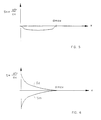
- the salient characteristic of the present invention is regulation of the frequency fr1 by changing the resonance frequency fr of the secondary resonator, and hence the distance x between the washer TM and said resonator, by means of the tuning screw VS, while holding constant the distance and hence the coupling between the two resonators.
- dmax indicates the maximum distance to which can be taken the washer TM in relation to the secondary resonator RDS.
- the washer can even touch the secondary resonator, cancelling out the influence thereof on the frequency fr, which becomes equal to fr1, while when moving away the washer said influence increases and the value of fr decreases toward fr2.
- fr frequency
- fr1 frequency of the electromagnetic energy
- FIGS. 3 and 6 What happens in known systems is shown in FIGS. 3 and 6.
- the variation of resonance frequency fr with the distance x is maximal for small x, i.e. when the secondary resonator draws close to the primary one and elongation of the tuning screw is maximal, whether with metal screw (curve frm) or dielectric screw (curve frd).
- the quartz glass SQS makes airtight the zone of the cavity where the greater part of the electromagnetic energy is concentrated, i.e. the only zone around the primary resonator RDP of real interest from the viewpoint of sensitivity to the variation of relative humidity of the surroundings. In this manner the rest of the resonant cavity can be provided without airtightness with obvious reduction of problems and costs.
Landscapes
- Control Of Motors That Do Not Use Commutators (AREA)
Applications Claiming Priority (2)
| Application Number | Priority Date | Filing Date | Title |
|---|---|---|---|
| ITMI911687A IT1248509B (it) | 1991-06-19 | 1991-06-19 | Cavita' risonante a microonde a doppio risonatore dielettrico con frequenza di risonanza sintonizzabile. |
| ITMI911687 | 1991-06-19 |
Publications (3)
| Publication Number | Publication Date |
|---|---|
| EP0519308A2 true EP0519308A2 (fr) | 1992-12-23 |
| EP0519308A3 EP0519308A3 (en) | 1993-08-04 |
| EP0519308B1 EP0519308B1 (fr) | 1997-04-02 |
Family
ID=11360156
Family Applications (1)
| Application Number | Title | Priority Date | Filing Date |
|---|---|---|---|
| EP92109750A Expired - Lifetime EP0519308B1 (fr) | 1991-06-19 | 1992-06-10 | Cavité résonnante pour hyperfréquences avec double résonateur diélectrique et fréquence de résonance réglable |
Country Status (9)
| Country | Link |
|---|---|
| EP (1) | EP0519308B1 (fr) |
| AU (1) | AU650545B2 (fr) |
| DE (1) | DE69218669T2 (fr) |
| ES (1) | ES2100252T3 (fr) |
| FI (1) | FI922856A7 (fr) |
| GR (1) | GR3023423T3 (fr) |
| IT (1) | IT1248509B (fr) |
| NO (1) | NO300348B1 (fr) |
| ZA (1) | ZA924474B (fr) |
Cited By (2)
| Publication number | Priority date | Publication date | Assignee | Title |
|---|---|---|---|---|
| WO1996011511A1 (fr) * | 1994-10-05 | 1996-04-18 | Nokia Telecommunications Oy | Resonateur dielectrique |
| WO1998054783A3 (fr) * | 1997-05-30 | 1999-03-04 | Ericsson Telefon Ab L M | Dispositif d'accord de filtres et plaque d'accord comportant un certain nombre de ces dispositifs |
Family Cites Families (2)
| Publication number | Priority date | Publication date | Assignee | Title |
|---|---|---|---|---|
| US4565979A (en) * | 1984-12-10 | 1986-01-21 | Ford Aerospace & Communications Corporation | Double dielectric resonator stabilized oscillator |
| US4922211A (en) * | 1988-04-15 | 1990-05-01 | Siemens Aktiengesellschaft | Microwave oscillator in which the dielectric resonator is hermetically sealed |
-
1991
- 1991-06-19 IT ITMI911687A patent/IT1248509B/it active IP Right Grant
-
1992
- 1992-06-10 ES ES92109750T patent/ES2100252T3/es not_active Expired - Lifetime
- 1992-06-10 DE DE69218669T patent/DE69218669T2/de not_active Expired - Fee Related
- 1992-06-10 EP EP92109750A patent/EP0519308B1/fr not_active Expired - Lifetime
- 1992-06-18 ZA ZA924474A patent/ZA924474B/xx unknown
- 1992-06-18 AU AU18380/92A patent/AU650545B2/en not_active Ceased
- 1992-06-18 FI FI922856A patent/FI922856A7/fi not_active Application Discontinuation
- 1992-06-19 NO NO922416A patent/NO300348B1/no unknown
-
1997
- 1997-05-15 GR GR970401072T patent/GR3023423T3/el unknown
Cited By (6)
| Publication number | Priority date | Publication date | Assignee | Title |
|---|---|---|---|---|
| WO1996011511A1 (fr) * | 1994-10-05 | 1996-04-18 | Nokia Telecommunications Oy | Resonateur dielectrique |
| US5677653A (en) * | 1994-10-05 | 1997-10-14 | Nokia Telecommunications Oy | Combined coarse and fine dielectric resonator frequency tuning mechanism |
| AU687260B2 (en) * | 1994-10-05 | 1998-02-19 | Nokia Telecommunications Oy | Dielectric resonator |
| WO1998054783A3 (fr) * | 1997-05-30 | 1999-03-04 | Ericsson Telefon Ab L M | Dispositif d'accord de filtres et plaque d'accord comportant un certain nombre de ces dispositifs |
| US6111484A (en) * | 1997-05-30 | 2000-08-29 | Telefonaktiebolaget Lm Ericsson | Filter tuning device and tuning plate including a number of such devices |
| AU744530B2 (en) * | 1997-05-30 | 2002-02-28 | Telefonaktiebolaget Lm Ericsson (Publ) | Filter tuning device and tuning plate including a number of such devices |
Also Published As
| Publication number | Publication date |
|---|---|
| EP0519308A3 (en) | 1993-08-04 |
| EP0519308B1 (fr) | 1997-04-02 |
| NO922416D0 (no) | 1992-06-19 |
| ZA924474B (en) | 1993-02-24 |
| GR3023423T3 (en) | 1997-08-29 |
| DE69218669D1 (de) | 1997-05-07 |
| FI922856A0 (fi) | 1992-06-18 |
| ES2100252T3 (es) | 1997-06-16 |
| FI922856A7 (fi) | 1992-12-20 |
| IT1248509B (it) | 1995-01-19 |
| DE69218669T2 (de) | 1997-10-30 |
| NO922416L (no) | 1992-12-21 |
| ITMI911687A1 (it) | 1992-12-19 |
| NO300348B1 (no) | 1997-05-12 |
| AU1838092A (en) | 1992-12-24 |
| ITMI911687A0 (it) | 1991-06-19 |
| AU650545B2 (en) | 1994-06-23 |
Similar Documents
| Publication | Publication Date | Title |
|---|---|---|
| US4639690A (en) | Tunable, dielectric-resonator-stabilized oscillator and method of tuning same | |
| US5777534A (en) | Inductor ring for providing tuning and coupling in a microwave dielectric resonator filter | |
| US4835498A (en) | Tunable microwave filtering device with dielectric resonator, and applications | |
| US5126696A (en) | W-Band waveguide variable controlled oscillator | |
| US6734766B2 (en) | Microwave filter having a temperature compensating element | |
| CA1208319A (fr) | Oscillateur stabilise a cavite a deux modes | |
| HUT62118A (en) | Temperature compensated helix resonator | |
| US4521746A (en) | Microwave oscillator with TM01δ dielectric resonator | |
| US4514707A (en) | Dielectric resonator controlled planar IMPATT diode oscillator | |
| EP1716619B1 (fr) | Resonateur accordable en tension, discret, constitue de materiau dielectrique | |
| EP0764996B1 (fr) | Résonateur diélectrique capable de varier sa fréquence de résonance | |
| US4124830A (en) | Waveguide filter employing dielectric resonators | |
| US6784768B1 (en) | Method and apparatus for coupling energy to/from dielectric resonators | |
| GB2261556A (en) | Adjusting resonance frequency of dielectric resonator | |
| US3621484A (en) | Helical resonator having variable capacitor which includes windings of reduced diameter as one plate thereof | |
| US4871983A (en) | Electronically tuned dielectric resonator stabilized oscillator | |
| EP0519308B1 (fr) | Cavité résonnante pour hyperfréquences avec double résonateur diélectrique et fréquence de résonance réglable | |
| US4673894A (en) | Oscillator coupled through cylindrical cavity for generating low noise microwaves | |
| US3882419A (en) | Varactor tuned impatt diode microwave oscillator | |
| US4794354A (en) | Apparatus and method for modifying microwave | |
| US5107164A (en) | Length-extentional quartz resonator | |
| WO2007028458A1 (fr) | Compensation en température de résonateurs à ligne combinée en utilisant un conducteur interne composite | |
| US4570137A (en) | Lumped-mode resonator | |
| JPH0661714A (ja) | 誘電体共振器 | |
| US4724403A (en) | Microwave oscillator |
Legal Events
| Date | Code | Title | Description |
|---|---|---|---|
| PUAI | Public reference made under article 153(3) epc to a published international application that has entered the european phase |
Free format text: ORIGINAL CODE: 0009012 |
|
| AK | Designated contracting states |
Kind code of ref document: A2 Designated state(s): DE ES FR GB GR IT SE |
|
| PUAL | Search report despatched |
Free format text: ORIGINAL CODE: 0009013 |
|
| AK | Designated contracting states |
Kind code of ref document: A3 Designated state(s): DE ES FR GB GR IT SE |
|
| 17P | Request for examination filed |
Effective date: 19931206 |
|
| 17Q | First examination report despatched |
Effective date: 19950912 |
|
| GRAG | Despatch of communication of intention to grant |
Free format text: ORIGINAL CODE: EPIDOS AGRA |
|
| GRAH | Despatch of communication of intention to grant a patent |
Free format text: ORIGINAL CODE: EPIDOS IGRA |
|
| RAP1 | Party data changed (applicant data changed or rights of an application transferred) |
Owner name: ITALTEL S.P.A. |
|
| GRAH | Despatch of communication of intention to grant a patent |
Free format text: ORIGINAL CODE: EPIDOS IGRA |
|
| GRAA | (expected) grant |
Free format text: ORIGINAL CODE: 0009210 |
|
| AK | Designated contracting states |
Kind code of ref document: B1 Designated state(s): DE ES FR GB GR IT SE |
|
| REF | Corresponds to: |
Ref document number: 69218669 Country of ref document: DE Date of ref document: 19970507 |
|
| PGFP | Annual fee paid to national office [announced via postgrant information from national office to epo] |
Ref country code: GB Payment date: 19970521 Year of fee payment: 6 |
|
| ET | Fr: translation filed | ||
| ITF | It: translation for a ep patent filed | ||
| PGFP | Annual fee paid to national office [announced via postgrant information from national office to epo] |
Ref country code: ES Payment date: 19970611 Year of fee payment: 6 |
|
| PGFP | Annual fee paid to national office [announced via postgrant information from national office to epo] |
Ref country code: SE Payment date: 19970612 Year of fee payment: 6 |
|
| REG | Reference to a national code |
Ref country code: ES Ref legal event code: FG2A Ref document number: 2100252 Country of ref document: ES Kind code of ref document: T3 |
|
| PGFP | Annual fee paid to national office [announced via postgrant information from national office to epo] |
Ref country code: GR Payment date: 19970620 Year of fee payment: 6 |
|
| PGFP | Annual fee paid to national office [announced via postgrant information from national office to epo] |
Ref country code: FR Payment date: 19970626 Year of fee payment: 6 |
|
| REG | Reference to a national code |
Ref country code: GR Ref legal event code: FG4A Free format text: 3023423 |
|
| PGFP | Annual fee paid to national office [announced via postgrant information from national office to epo] |
Ref country code: DE Payment date: 19970820 Year of fee payment: 6 |
|
| PLBE | No opposition filed within time limit |
Free format text: ORIGINAL CODE: 0009261 |
|
| STAA | Information on the status of an ep patent application or granted ep patent |
Free format text: STATUS: NO OPPOSITION FILED WITHIN TIME LIMIT |
|
| 26N | No opposition filed | ||
| PG25 | Lapsed in a contracting state [announced via postgrant information from national office to epo] |
Ref country code: GB Free format text: LAPSE BECAUSE OF NON-PAYMENT OF DUE FEES Effective date: 19980610 |
|
| PG25 | Lapsed in a contracting state [announced via postgrant information from national office to epo] |
Ref country code: SE Free format text: LAPSE BECAUSE OF NON-PAYMENT OF DUE FEES Effective date: 19980611 Ref country code: ES Free format text: LAPSE BECAUSE OF EXPIRATION OF PROTECTION Effective date: 19980611 |
|
| PG25 | Lapsed in a contracting state [announced via postgrant information from national office to epo] |
Ref country code: GR Free format text: LAPSE BECAUSE OF NON-PAYMENT OF DUE FEES Effective date: 19980630 |
|
| GBPC | Gb: european patent ceased through non-payment of renewal fee |
Effective date: 19980610 |
|
| PG25 | Lapsed in a contracting state [announced via postgrant information from national office to epo] |
Ref country code: FR Free format text: LAPSE BECAUSE OF NON-PAYMENT OF DUE FEES Effective date: 19990226 |
|
| EUG | Se: european patent has lapsed |
Ref document number: 92109750.7 |
|
| PG25 | Lapsed in a contracting state [announced via postgrant information from national office to epo] |
Ref country code: DE Free format text: LAPSE BECAUSE OF NON-PAYMENT OF DUE FEES Effective date: 19990401 |
|
| REG | Reference to a national code |
Ref country code: FR Ref legal event code: ST |
|
| REG | Reference to a national code |
Ref country code: ES Ref legal event code: FD2A Effective date: 20000601 |
|
| PG25 | Lapsed in a contracting state [announced via postgrant information from national office to epo] |
Ref country code: IT Free format text: LAPSE BECAUSE OF NON-PAYMENT OF DUE FEES Effective date: 20050610 |