EP0519355A1 - Culasse pour un moteur à combustion interne - Google Patents
Culasse pour un moteur à combustion interne Download PDFInfo
- Publication number
- EP0519355A1 EP0519355A1 EP92109971A EP92109971A EP0519355A1 EP 0519355 A1 EP0519355 A1 EP 0519355A1 EP 92109971 A EP92109971 A EP 92109971A EP 92109971 A EP92109971 A EP 92109971A EP 0519355 A1 EP0519355 A1 EP 0519355A1
- Authority
- EP
- European Patent Office
- Prior art keywords
- cylinder head
- intake air
- cylinder
- collecting duct
- head according
- Prior art date
- Legal status (The legal status is an assumption and is not a legal conclusion. Google has not performed a legal analysis and makes no representation as to the accuracy of the status listed.)
- Withdrawn
Links
- 238000002485 combustion reaction Methods 0.000 title claims abstract description 12
- 238000009413 insulation Methods 0.000 claims description 12
- 238000002955 isolation Methods 0.000 claims description 4
- 238000001816 cooling Methods 0.000 claims description 3
- 239000007789 gas Substances 0.000 description 20
- 238000000926 separation method Methods 0.000 description 2
- 229910001060 Gray iron Inorganic materials 0.000 description 1
- 230000017525 heat dissipation Effects 0.000 description 1
- 238000009434 installation Methods 0.000 description 1
- 238000003754 machining Methods 0.000 description 1
- 238000004519 manufacturing process Methods 0.000 description 1
- 238000003801 milling Methods 0.000 description 1
Images


Classifications
-
- F—MECHANICAL ENGINEERING; LIGHTING; HEATING; WEAPONS; BLASTING
- F02—COMBUSTION ENGINES; HOT-GAS OR COMBUSTION-PRODUCT ENGINE PLANTS
- F02F—CYLINDERS, PISTONS OR CASINGS, FOR COMBUSTION ENGINES; ARRANGEMENTS OF SEALINGS IN COMBUSTION ENGINES
- F02F1/00—Cylinders; Cylinder heads
- F02F1/24—Cylinder heads
- F02F1/243—Cylinder heads and inlet or exhaust manifolds integrally cast together
Definitions
- the invention relates to a cylinder head for an internal combustion engine, which is in particular a self-igniting internal combustion engine.
- an internal combustion engine which is in particular a self-igniting internal combustion engine.
- These are primarily multi-cylinder internal combustion engines, with a common cylinder head covering the cylinders.
- a generic cylinder head is known from DE-OS 31 01 881.
- the cylinder head known from this publication is designed in particular for large engines, for example for ship propulsion systems. Accordingly, this cylinder head is primarily designed as a single cylinder head with a molded intake air collection duct and exhaust gas collection duct. The collecting channels are arranged on opposite sides of the cylinder head and are connected to one another by connecting elements.
- This cylinder head is completely tailored to the requirements of marine engines, in which the interchangeability of individual cylinder units should be feasible without the disassembly of adjacent cylinders. Due to this requirement, the exhaust manifold and the intake air manifold are arranged on opposite sides of the cylinder head for good assembly accessibility. Such a thing A trained cylinder head requires a large amount of installation space and assembly work, and in the case of a desired supercharging, connecting lines between the exhaust and intake side are still required via the cylinder head or the cylinder head end faces.
- the object of the invention is to provide a cylinder head which, with good thermal properties, has a compact structure and can be assembled with little effort overall.
- This object is achieved in that the exhaust gas collection duct and the intake air collection duct are arranged one above the other on a cylinder head side, an air-flowed insulation space being arranged between the exhaust gas collection duct and the intake air collection duct.
- the exhaust manifold is made in one piece with the cylinder head and arranged below the intake air manifold.
- the combustion air is conducted through the cooler, upper region of the cylinder head to the gas exchange valves, while the hot lower region of the cylinder head, including the exhaust gas collection duct, is arranged in a thermally insulated manner from the intake air collection duct.
- the exhaust manifold is made in one piece with the cylinder head if due of the other components to be connected, such as exhaust silencers or exhaust gas turbochargers, there are no different requirements for the exhaust manifold.
- it is further provided to cast the cylinder head in particular from gray cast iron.
- the cores for forming the gas exchange channels can be combined to form a common core rake or core bar.
- the core bar unifying the exhaust gas channels can also be designed so that it also forms the exhaust gas collecting channel at the same time.
- the insulation space runs out into insulation arms projecting into the cylinder head.
- these isolation arms can extend as far as the combustion chamber base plate of the cylinder head. This achieves an effective separation of the gas exchange channels, which have different temperatures, as previously stated.
- the collecting channels can be provided on the outside with cooling fins and / or can be waffle-shaped. This ensures good heat transfer, which is particularly advantageous for heat dissipation from the exhaust manifold.
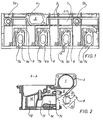
- the cylinder head according to FIG. 1 has a cast-on intake air collecting duct 1.
- the inlet air collecting duct 1 has cooling fins 2 on the outside in such a way that the duct as a whole is waffle-shaped.
- the intake air collecting duct 1 is provided with an opening 3 and a flange 4 surrounding it.
- An air intake line is attached to this flange 4 by means of screws.
- the inlet air collecting duct 1 further has two cylindrical openings 5a, 5b, which are located at the level of the first and third cylinders. Through these openings 5a, 5b, a core bar forming the intake air collecting duct 1 can be fixed in addition to a holder through the opening 3.
- a thread is cut into the openings 5a, 5b, into which a screw plug is screwed. It is also intended to use measuring or control sensors in the openings 5a, 5b.
- Exhaust ducts 6a, 6b, 6c, 6d open below the intake air collecting duct 1.
- the exhaust channels 6a, 6b, 6c, 6d have flange connections 7a, 7b, 7c, 7d, to which an individually designed exhaust manifold 8 (FIG. 2) is attached.
- an air-flowed insulation space 9 is arranged, from which the insulation arms 10 extend to the valve stem guides 11 of the gas exchange valves and further down to the combustion chamber base plate 12. This ensures effective isolation of the gas exchange channels from one another.
- the cylinder head according to FIG. 3 has, in addition to the intake air collecting duct 1, a likewise cast-on exhaust gas collecting duct 13, which is connected to the exhaust gas ducts 6a, 6b, 6c, 6d.
- the exhaust manifold 13 has a connecting flange 14 to which a further exhaust pipe or an exhaust gas turbocharger can be attached.
- the connecting flange 14 is arranged in the region of the third cylinder.
- the connecting flange 14 and also the flange 4 are arranged at a suitable other location on the ducts, for example on the end faces of the cylinder head (FIG. 4, FIG. 5).
- FIG. 6 shows, analogously to FIG. 2, the arrangement of the insulation space 9 with the insulation arms 10 adjoining it up to the combustion chamber base plate 12.
- the intake air collecting duct 1, which is made in one piece with the cylinder head, and the exhaust gas collecting duct 13, which is made in one piece with the cylinder head, are flush with the end faces of the cylinder head. This simplifies production because all flange machining can be carried out with one milling operation.
Landscapes
- Engineering & Computer Science (AREA)
- Chemical & Material Sciences (AREA)
- Combustion & Propulsion (AREA)
- Mechanical Engineering (AREA)
- General Engineering & Computer Science (AREA)
- Cylinder Crankcases Of Internal Combustion Engines (AREA)
Applications Claiming Priority (2)
| Application Number | Priority Date | Filing Date | Title |
|---|---|---|---|
| DE19914120200 DE4120200A1 (de) | 1991-06-19 | 1991-06-19 | Zylinderkopf fuer eine brennkraftmaschine |
| DE4120200 | 1991-06-19 |
Publications (1)
| Publication Number | Publication Date |
|---|---|
| EP0519355A1 true EP0519355A1 (fr) | 1992-12-23 |
Family
ID=6434275
Family Applications (1)
| Application Number | Title | Priority Date | Filing Date |
|---|---|---|---|
| EP92109971A Withdrawn EP0519355A1 (fr) | 1991-06-19 | 1992-06-13 | Culasse pour un moteur à combustion interne |
Country Status (2)
| Country | Link |
|---|---|
| EP (1) | EP0519355A1 (fr) |
| DE (1) | DE4120200A1 (fr) |
Cited By (4)
| Publication number | Priority date | Publication date | Assignee | Title |
|---|---|---|---|---|
| EP1959123A1 (fr) | 2007-02-15 | 2008-08-20 | Peugeot Citroen Automobiles SA | Moteur à combustion interne comportant un répartiteur d'admission d'air et procédé de fabrication d'un tel répartiteur |
| DE102007046657A1 (de) * | 2007-09-28 | 2009-04-09 | Audi Ag | Brennkraftmaschine |
| DE102007057310A1 (de) * | 2007-11-28 | 2009-06-04 | Continental Automotive Gmbh | Verbrennungsmotor mit integrierten Abgaskrümmern |
| DE102010060785A1 (de) * | 2010-11-25 | 2012-05-31 | Dr. Ing. H.C. F. Porsche Aktiengesellschaft | Zylinderkopf einer Brennkraftmaschine |
Citations (4)
| Publication number | Priority date | Publication date | Assignee | Title |
|---|---|---|---|---|
| US2257631A (en) * | 1939-11-13 | 1941-09-30 | Nash Kelvinator Corp | Internal combustion engine |
| GB1031571A (en) * | 1964-01-14 | 1966-06-02 | Henry Weslake | Improvements in or relating to cylinder heads for internal combustion engines |
| DE3815408A1 (de) * | 1987-05-22 | 1988-12-08 | Steyr Daimler Puch Ag | Abgaseinrichtung fuer mehrzylinder-brennkraftmaschinen |
| EP0309418A2 (fr) * | 1987-09-23 | 1989-03-29 | FIAT AUTO S.p.A. | Culasse pour moteur à combustion interne |
Family Cites Families (3)
| Publication number | Priority date | Publication date | Assignee | Title |
|---|---|---|---|---|
| DE1044509B (de) * | 1954-12-11 | 1958-11-20 | Wolfgang Denzel | Geblaeseluftgekuehlte gemischverdichtende Brennkraftmaschine mit Fremdzuendung |
| DE1922943A1 (de) * | 1969-05-06 | 1970-12-10 | Wakofic Bautechnik Gmbh & Co K | Lueftungsschachtanlage |
| DE3101881A1 (de) * | 1981-01-22 | 1982-08-26 | Klöckner-Humboldt-Deutz AG, 5000 Köln | Zylinderkopf fuer brennkraftmaschinen |
-
1991
- 1991-06-19 DE DE19914120200 patent/DE4120200A1/de not_active Withdrawn
-
1992
- 1992-06-13 EP EP92109971A patent/EP0519355A1/fr not_active Withdrawn
Patent Citations (4)
| Publication number | Priority date | Publication date | Assignee | Title |
|---|---|---|---|---|
| US2257631A (en) * | 1939-11-13 | 1941-09-30 | Nash Kelvinator Corp | Internal combustion engine |
| GB1031571A (en) * | 1964-01-14 | 1966-06-02 | Henry Weslake | Improvements in or relating to cylinder heads for internal combustion engines |
| DE3815408A1 (de) * | 1987-05-22 | 1988-12-08 | Steyr Daimler Puch Ag | Abgaseinrichtung fuer mehrzylinder-brennkraftmaschinen |
| EP0309418A2 (fr) * | 1987-09-23 | 1989-03-29 | FIAT AUTO S.p.A. | Culasse pour moteur à combustion interne |
Cited By (5)
| Publication number | Priority date | Publication date | Assignee | Title |
|---|---|---|---|---|
| EP1959123A1 (fr) | 2007-02-15 | 2008-08-20 | Peugeot Citroen Automobiles SA | Moteur à combustion interne comportant un répartiteur d'admission d'air et procédé de fabrication d'un tel répartiteur |
| FR2912784A1 (fr) * | 2007-02-15 | 2008-08-22 | Peugeot Citroen Automobiles Sa | Moteur a combustion interne comportant un repartiteur d'admission d'air et procede de fabrication d'un tel repartiteur |
| DE102007046657A1 (de) * | 2007-09-28 | 2009-04-09 | Audi Ag | Brennkraftmaschine |
| DE102007057310A1 (de) * | 2007-11-28 | 2009-06-04 | Continental Automotive Gmbh | Verbrennungsmotor mit integrierten Abgaskrümmern |
| DE102010060785A1 (de) * | 2010-11-25 | 2012-05-31 | Dr. Ing. H.C. F. Porsche Aktiengesellschaft | Zylinderkopf einer Brennkraftmaschine |
Also Published As
| Publication number | Publication date |
|---|---|
| DE4120200A1 (de) | 1992-12-24 |
Similar Documents
| Publication | Publication Date | Title |
|---|---|---|
| DE60107748T2 (de) | Brennkraftmaschine mit Abgasrückführungssystem, insbesondere für Fahrzeuge | |
| EP0232467B1 (fr) | Moteur à combustion interne polycylindre | |
| DE102007053126B4 (de) | Brennkraftmaschine mit gekühlter Abgasrückführung sowie Abgaskrümmer | |
| DE69308768T2 (de) | Zylinderkopf-Kühlstruktur für eine Mehrventil-Brennkraftmaschine | |
| DE69921553T2 (de) | Einlasssystem für Brennkraftmaschine | |
| DE10222078B4 (de) | Mehrzylindermotor | |
| EP0952329A2 (fr) | Moteur à combustion interne avec un front-end intégré | |
| DE4038169C2 (fr) | ||
| EP0519355A1 (fr) | Culasse pour un moteur à combustion interne | |
| DE4316333C1 (de) | Abgasleitung | |
| EP0515925B1 (fr) | Culasse pour moteur à combustion | |
| EP0897057B1 (fr) | Culasse à quatre soupapes pour un moteur à combustion interne | |
| DE60305176T2 (de) | Abgaskrümmer und Brennkraftmaschine mit einem Abgaskrümmer | |
| EP1062411B1 (fr) | Conduite pour gaz d'echappement refroidie par eau | |
| EP0709557B1 (fr) | Dispositif de soufflage d'air dans un tuyau d'échappement | |
| DE3929124C2 (de) | Brennkraftmaschine mit einem Aufladeaggregat | |
| DE2508952C2 (de) | Zylindergehäuse für eine mehrzylindrige Viertakt-Brennkraftmaschine | |
| DE102010030793A1 (de) | Spiegelbild-Zylinderköpfe | |
| EP1008736B1 (fr) | Arrêteur de flammes pour un moteur à gaz | |
| DE3343420C2 (de) | Zweitaktbrennkraftmaschine | |
| DE3643674A1 (de) | Mehrzylindrige brennkraftmaschine | |
| DE4018620C2 (de) | Aufgeladener Dieselmotor | |
| EP0782667B1 (fr) | Tubulure d'air de combustion d'un moteur a combustion interne | |
| DE10346005B4 (de) | Luftansaugmodul für eine Brennkraftmaschine mit Impulsaufladung | |
| EP0394752B1 (fr) | Moteur à combustion à refroidissement liquide avec un refroidisseur intermédiaire |
Legal Events
| Date | Code | Title | Description |
|---|---|---|---|
| PUAI | Public reference made under article 153(3) epc to a published international application that has entered the european phase |
Free format text: ORIGINAL CODE: 0009012 |
|
| 17P | Request for examination filed |
Effective date: 19920908 |
|
| AK | Designated contracting states |
Kind code of ref document: A1 Designated state(s): DE FR GB IT |
|
| 17Q | First examination report despatched |
Effective date: 19940418 |
|
| STAA | Information on the status of an ep patent application or granted ep patent |
Free format text: STATUS: THE APPLICATION HAS BEEN WITHDRAWN |
|
| 18W | Application withdrawn |
Withdrawal date: 19940728 |