EP0519610A1 - Dispositif de coupe - Google Patents
Dispositif de coupe Download PDFInfo
- Publication number
- EP0519610A1 EP0519610A1 EP92304784A EP92304784A EP0519610A1 EP 0519610 A1 EP0519610 A1 EP 0519610A1 EP 92304784 A EP92304784 A EP 92304784A EP 92304784 A EP92304784 A EP 92304784A EP 0519610 A1 EP0519610 A1 EP 0519610A1
- Authority
- EP
- European Patent Office
- Prior art keywords
- cutting blade
- press rod
- handle
- brake
- press
- Prior art date
- Legal status (The legal status is an assumption and is not a legal conclusion. Google has not performed a legal analysis and makes no representation as to the accuracy of the status listed.)
- Withdrawn
Links
- 238000005520 cutting process Methods 0.000 title claims abstract description 58
- 239000004744 fabric Substances 0.000 claims abstract description 20
- 238000010586 diagram Methods 0.000 description 4
- 238000007796 conventional method Methods 0.000 description 2
- 230000000694 effects Effects 0.000 description 2
- 230000005611 electricity Effects 0.000 description 1
- 230000002093 peripheral effect Effects 0.000 description 1
- 230000003578 releasing effect Effects 0.000 description 1
Images


Classifications
-
- D—TEXTILES; PAPER
- D06—TREATMENT OF TEXTILES OR THE LIKE; LAUNDERING; FLEXIBLE MATERIALS NOT OTHERWISE PROVIDED FOR
- D06H—MARKING, INSPECTING, SEAMING OR SEVERING TEXTILE MATERIALS
- D06H7/00—Apparatus or processes for cutting, or otherwise severing, specially adapted for the cutting, or otherwise severing, of textile materials
-
- B—PERFORMING OPERATIONS; TRANSPORTING
- B26—HAND CUTTING TOOLS; CUTTING; SEVERING
- B26D—CUTTING; DETAILS COMMON TO MACHINES FOR PERFORATING, PUNCHING, CUTTING-OUT, STAMPING-OUT OR SEVERING
- B26D7/00—Details of apparatus for cutting, cutting-out, stamping-out, punching, perforating, or severing by means other than cutting
- B26D7/22—Safety devices specially adapted for cutting machines
- B26D7/24—Safety devices specially adapted for cutting machines arranged to disable the operating means for the cutting member
-
- B—PERFORMING OPERATIONS; TRANSPORTING
- B26—HAND CUTTING TOOLS; CUTTING; SEVERING
- B26D—CUTTING; DETAILS COMMON TO MACHINES FOR PERFORATING, PUNCHING, CUTTING-OUT, STAMPING-OUT OR SEVERING
- B26D7/00—Details of apparatus for cutting, cutting-out, stamping-out, punching, perforating, or severing by means other than cutting
- B26D7/22—Safety devices specially adapted for cutting machines
Definitions
- the present invention relates to a cutting apparatus having a safety device.
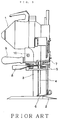
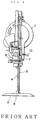
- reference numerals 1, 2 and 3 represent a motor portion, a bed and a pole, respectively, and the motor portion 1 is set on the bed 2 by the pole 3.
- a cutting blade 4 is arranged along this pole 3, and the top end of the cutting blade 4 is connected to a driving part of the motor portion 1 and the lower end is contained in a slit hole formed in the bed 2. Within this contained narrow space, the cutting blade 4 is vertically reciprocated at a high speed to cut a cloth placed on the bed 2.
- Reference numeral 5 represents a press rod vertically moving along the pole 3, and a cloth press 6 is attached to the lower end of the press rod 5.
- Reference numeral 7 represents a brake for supporting this press rod 5, which holds the cloth press 6 at a desired height. This brake 7 is urged in the direction pressing the press rod 5 by means of a spring, and the press rod 5 is held in the state pressed by the brake 7.
- Reference numeral 8 represents a release lever connected to the brake 7, and by operating this release lever 8, the brake 7 is caused to release the pressing of the spring of the press rod 5 and the press rod 5 is made movable.
- Reference numeral 9 represents a handle, and the rear end of the release lever 8 is located in the vicinity of this handle 9 so that the release lever 8 is manipulated by the hand gripping the handle 9.
- Reference numeral 10 represents a driving switch 10 which also is operated by the hand gripping the handle 9.
- the bed 2 is slipped between a table and piled layers of cloth placed on the table, and the cloth is spread on the bed 2 and the brake 7 is released by the release lever 8 to move the press rod 5 and make the height of the cloth press 6 in agreement with the height of the cloth, whereby the cloth just in front of the cutting blade 4 is pressed for the cutting operation.
- the above-mentioned structure includes the following states.
- Another object of the present invention is to prevent an unforeseen accident by stopping the motion of cutting blade automaticaly while the operater separates his hand from the handle.
- Still another object of the present invention is to prevent an unforeseen accident by preventing the cutting blade to drive even if the driving switch is ON when the power becomes ON.
- a cutting apparatus comprising a cutting blade arranged along a pole pendent from a motor portion, a press rod having a cloth press attached to the lower end thereof, which is vertically movably arranged at a front part of the cutting blade, and a brake disposed to confront the press rod for controlling the vertical movement of the press rod, wherein a guard covering the cutting blade is attached to the press rod, a handle is provided with a lever to be actuated when the handle is gripped, a switch of the motor portion to be actuated by the operation of the lever is connected to open and close the brake, and a power source is separately arranged.
- the press rod when the handle is gripped, the press rod is braked and simultaneously, the switch is turned on, and the power source switch is turned on and cutting becomes possible.
- the press rod descends and the cutting blade is covered by the guard and simultaneously, the switch is turned off and driving of the cutting blade is stopped. furthermore, even if power failure is caused in the state where the switch is turned on and this turn-on state is kept, the cutting blade does not begin the movement again abruptly on release of the power failure.
- Fig. 1 is a side view showing the entire structure of an embodiment.
- Fig.2 is a front view illustrating the entire structure.
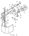
- Fig. 3 is a diagram illustrating a main part.
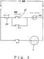
- Fig. 4 is an electric circuit diagram.
- Fig. 5 is a side view showing the entire structure of the conventional apparatus.
- Fig. 6 is a front view showing the entire structure of the conventional apparatus.
- Fig. 1 is a side view of the entire structure
- Fig. 2 is a front view of the entire structure
- Fig. 3 is a diagram illustrating a main part
- Fig. 4 is an electiric circuit diagram.
- reference numerals 1, 2 and 3 represent a motor portion, a bed and a pole, respectively, and the motor portion 1 is set on the bed 2 by the pole 3. furthermore, a cutting blade 4 is arranged along the pole 3.
- Reference numeral 5 represents a press rod 5 which moves vertically along the pole 3 and a cloth press 6 is attached to the lower end of the press rod 5. These members are the same as those described above with respect to the conventional technique.
- Reference numeral 12 represents a brake supporting this press rod 5, and the brake 12 is disposed to maintain the cloth press 6 at a desired height as in the above-mentioned conventional technique.
- the top end of the brake 12 is rotatably supported on the apparatus proper and the top end of an operating shaft 13 is fixed to the lower portion of the brake 12.
- Reference numeral 14 represents a handle attached to the apparatus proper, and a groove 14a extending in the longitudinal direction is formed on the handle 14.
- a lever 15 is arranged rotatably along this groove 14a, and the top end of this lever 15 is connected to a swinging member 17 having a lower end swingably arranged on a plate 16 attached to the apparatus proper in front of the handle 14, whereby the above-mentioned rotation operation is made possible.
- a spring 18 is disposed between the swinging member 17 and the handle 14 to press and urge the swinging member 17 forward,
- the rear end of the operation shaft 13 is connected to this swinging member 17 through a spring 19, whereby the lever 15 is connected to the operation shaft 13 through the swinging member 17 and the plate 12 connected to the top end of the operation shaft 13 is urged in the direction separating from the press rod 5 by the elastic force of the spring,
- the spring 19 is arranged so that the operation shaft 13 is drawn backward and the spring 19 acts in the direction where the plate 12 impinges against the press rod 5.
- the elastic force of the spring 19 is weaker than that of the spring 18 and the motion of the swinging member 17 is not substantially influenced by the elastic force of the spring 19.
- Reference numeral 20 represents a brake release lever rotatably supported on the apparatus proper, and the top end of the lever 20 is connected to or impinges against the lower part of the brake 12.
- the rear end of the lever 20 is extended to the vicinity of the handle 14 so that the lever 20 can be operated by the hand gripping the handle 14. If the rear end of the lever 20 is operated, the brake 12 is rotated against the elastic force of the spring 19 to move the brake 12 in the direction separating from the press rod 5.
- Reference numeral 21 represents a power source switch
- reference numeral 22 represents a switch
- reference numeral 23 represents a relay coil
- an electric circuit for these members is as shown in Fig. 4.
- the press rod 5 provided with the guard 11 is brought up by picking up a knob, and (2) the handle 14 is gripped by the other hand, whereby the lever 15 is caused to sink in the groove 14a and simultaneously, the switch 22 is turned on.
- the cutting operation is carried out while moving the bed on the table on which cloth is placed.
- the present invention there can also be adopted a structure in which the bed is not disposed and the cutting operation is carried out while hanging down the cutting apparatus from above.
- the present invention provides a cutting apparatus comprising a cutting blade arranged along a pole pendent from a motor portion, a press rod having a cloth press attached to the lower end thereof, which is vertically movably arranged at a front part of the cutting blade, and a brake disposed to confront the press rod for controlling the vertical movement of the press rod, wherein a guard covering the cutting blade is attached to the press rod, a handle is provided with a lever to be actuated when the handle is gripped, a switch of the motor portion to be actuated by the operation of the lever is connected to open and close the brake, and a power source is separately arranged, there can be attained an effect that when the operater's hand is separated from the handle, the press rod is brought down and the guard covers the cutting blade, and therefore the cutting blade is covered while the operater separates his hand from the handle.
- the switch is turned off, and therefore, the cutting blade is stopped when the worker separates his hand from the handle.
Landscapes
- Engineering & Computer Science (AREA)
- Life Sciences & Earth Sciences (AREA)
- Forests & Forestry (AREA)
- Mechanical Engineering (AREA)
- Textile Engineering (AREA)
- Nonmetal Cutting Devices (AREA)
- Details Of Cutting Devices (AREA)
- Control Of Cutting Processes (AREA)
Applications Claiming Priority (2)
| Application Number | Priority Date | Filing Date | Title |
|---|---|---|---|
| JP155238/91 | 1991-05-31 | ||
| JP3155238A JP3026301B2 (ja) | 1991-05-31 | 1991-05-31 | 裁断機 |
Publications (1)
| Publication Number | Publication Date |
|---|---|
| EP0519610A1 true EP0519610A1 (fr) | 1992-12-23 |
Family
ID=15601560
Family Applications (1)
| Application Number | Title | Priority Date | Filing Date |
|---|---|---|---|
| EP92304784A Withdrawn EP0519610A1 (fr) | 1991-05-31 | 1992-05-27 | Dispositif de coupe |
Country Status (5)
| Country | Link |
|---|---|
| US (1) | US5274923A (fr) |
| EP (1) | EP0519610A1 (fr) |
| JP (1) | JP3026301B2 (fr) |
| KR (1) | KR100203541B1 (fr) |
| AU (1) | AU654012B2 (fr) |
Cited By (2)
| Publication number | Priority date | Publication date | Assignee | Title |
|---|---|---|---|---|
| FR2710578A1 (fr) * | 1993-09-30 | 1995-04-07 | Meier Freres | Machine pour couper des meules de fromage. |
| EP0945232A3 (fr) * | 1998-03-24 | 2000-07-19 | Staples Group PLC | Dispositif de protection de la lame pour des machines de coupe |
Families Citing this family (4)
| Publication number | Priority date | Publication date | Assignee | Title |
|---|---|---|---|---|
| JP2502940Y2 (ja) * | 1991-09-30 | 1996-06-26 | 保 五月女 | 布生地用裁断機の安全装置 |
| JP2015077078A (ja) * | 2013-10-15 | 2015-04-23 | 株式会社ササキコーポレーション | 球根野菜調整装置 |
| CN112095332A (zh) * | 2020-09-29 | 2020-12-18 | 齐秋梅 | 一种用于服装面料加工的裁剪平台 |
| CN113152065B (zh) * | 2021-01-29 | 2022-10-28 | 浙江大学山东工业技术研究院 | 一种高性能防护服自动化生产系统 |
Citations (6)
| Publication number | Priority date | Publication date | Assignee | Title |
|---|---|---|---|---|
| US1678989A (en) * | 1925-07-23 | 1928-07-31 | Maimin Company Inc H | Cloth-cutting machine |
| EP0018934A1 (fr) * | 1979-04-26 | 1980-11-12 | Claude Creton | Dispositif de protection adaptable sur les coupeuses à lames verticales |
| FR2507285A2 (fr) * | 1980-11-27 | 1982-12-10 | Memo Sarl | Dispositif de protection pour appareils de coupe ou analogue a commande manuelle |
| EP0193672A1 (fr) * | 1985-02-11 | 1986-09-10 | Eastman Machine Company | Machine à découper et dispositif de sécurité |
| FR2594453A1 (fr) * | 1986-02-17 | 1987-08-21 | Etwa | Dispositif de protection pour une machine electrique a couper les tissus |
| US4698910A (en) * | 1985-09-06 | 1987-10-13 | Acraloc Corporation | Safety device for cloth cutting machines |
Family Cites Families (3)
| Publication number | Priority date | Publication date | Assignee | Title |
|---|---|---|---|---|
| US1283895A (en) * | 1918-04-03 | 1918-11-05 | Robert A Read | Cloth-cutter guard. |
| US2293021A (en) * | 1941-11-19 | 1942-08-11 | Morando Emanuel Rodriguez | Cloth cutting machine |
| DE2619789C3 (de) * | 1976-05-05 | 1982-03-11 | Krauss U. Reichert Gmbh + Co Kg Spezialmaschinenfabrik, 7012 Fellbach | Stoßmesser-Zuschneidemaschine mit Messerschutz |
-
1991
- 1991-05-31 JP JP3155238A patent/JP3026301B2/ja not_active Expired - Lifetime
-
1992
- 1992-05-27 EP EP92304784A patent/EP0519610A1/fr not_active Withdrawn
- 1992-05-28 KR KR1019920009098A patent/KR100203541B1/ko not_active Expired - Fee Related
- 1992-05-29 US US07/891,415 patent/US5274923A/en not_active Expired - Fee Related
- 1992-05-29 AU AU17311/92A patent/AU654012B2/en not_active Ceased
Patent Citations (6)
| Publication number | Priority date | Publication date | Assignee | Title |
|---|---|---|---|---|
| US1678989A (en) * | 1925-07-23 | 1928-07-31 | Maimin Company Inc H | Cloth-cutting machine |
| EP0018934A1 (fr) * | 1979-04-26 | 1980-11-12 | Claude Creton | Dispositif de protection adaptable sur les coupeuses à lames verticales |
| FR2507285A2 (fr) * | 1980-11-27 | 1982-12-10 | Memo Sarl | Dispositif de protection pour appareils de coupe ou analogue a commande manuelle |
| EP0193672A1 (fr) * | 1985-02-11 | 1986-09-10 | Eastman Machine Company | Machine à découper et dispositif de sécurité |
| US4698910A (en) * | 1985-09-06 | 1987-10-13 | Acraloc Corporation | Safety device for cloth cutting machines |
| FR2594453A1 (fr) * | 1986-02-17 | 1987-08-21 | Etwa | Dispositif de protection pour une machine electrique a couper les tissus |
Cited By (2)
| Publication number | Priority date | Publication date | Assignee | Title |
|---|---|---|---|---|
| FR2710578A1 (fr) * | 1993-09-30 | 1995-04-07 | Meier Freres | Machine pour couper des meules de fromage. |
| EP0945232A3 (fr) * | 1998-03-24 | 2000-07-19 | Staples Group PLC | Dispositif de protection de la lame pour des machines de coupe |
Also Published As
| Publication number | Publication date |
|---|---|
| KR100203541B1 (ko) | 1999-06-15 |
| AU1731192A (en) | 1992-12-03 |
| KR920021794A (ko) | 1992-12-18 |
| US5274923A (en) | 1994-01-04 |
| JPH04354694A (ja) | 1992-12-09 |
| AU654012B2 (en) | 1994-10-20 |
| JP3026301B2 (ja) | 2000-03-27 |
Similar Documents
| Publication | Publication Date | Title |
|---|---|---|
| US4523911A (en) | Foot-actuated control arrangment particularly for dental arrangment | |
| US3963890A (en) | Foot operated switch assembly with latching structure for operator | |
| US4528488A (en) | Warning device using power tool residual kinetic energy | |
| JPS61146449A (ja) | 安全フード | |
| GB9904481D0 (en) | Locking arrangemnt for table saw guard | |
| US2713407A (en) | Chuck key safety switch mechanism | |
| US5274923A (en) | Cutting apparatus | |
| US6478124B2 (en) | Brake device for a drive machine of an elevator | |
| US4050151A (en) | Dry-shaving apparatus | |
| US11939189B2 (en) | Frictionless electronic safety actuator | |
| JP3319725B2 (ja) | プレス機械のガード式安全装置 | |
| US4698910A (en) | Safety device for cloth cutting machines | |
| JP3611692B2 (ja) | リニアモータ走行軸の機械ブレーキ機構 | |
| JPH0519060B2 (fr) | ||
| US6918279B2 (en) | Blind riveting device | |
| US3137189A (en) | Paper cutter with unicyclic drive means | |
| EP4332044A1 (fr) | Actionneur de frein de sécurité | |
| JPS61188097A (ja) | 切断機 | |
| JPH0813543B2 (ja) | 印刷機主駆動電動機用制動装置 | |
| JP5492463B2 (ja) | フットスイッチ装置 | |
| EP0779133A3 (fr) | Machine à découper avec poignée détecteur | |
| US2957057A (en) | Control operating means | |
| JPH029384Y2 (fr) | ||
| JP3014262U (ja) | 断裁機用安全装置 | |
| US1384107A (en) | Cutting-machine |
Legal Events
| Date | Code | Title | Description |
|---|---|---|---|
| PUAI | Public reference made under article 153(3) epc to a published international application that has entered the european phase |
Free format text: ORIGINAL CODE: 0009012 |
|
| AK | Designated contracting states |
Kind code of ref document: A1 Designated state(s): DE FR GB IT |
|
| 17P | Request for examination filed |
Effective date: 19930505 |
|
| 17Q | First examination report despatched |
Effective date: 19950214 |
|
| STAA | Information on the status of an ep patent application or granted ep patent |
Free format text: STATUS: THE APPLICATION IS DEEMED TO BE WITHDRAWN |
|
| 18D | Application deemed to be withdrawn |
Effective date: 19960319 |