EP0519637A1 - Apparat mittels magnetischer Resonanz - Google Patents
Apparat mittels magnetischer Resonanz Download PDFInfo
- Publication number
- EP0519637A1 EP0519637A1 EP92305317A EP92305317A EP0519637A1 EP 0519637 A1 EP0519637 A1 EP 0519637A1 EP 92305317 A EP92305317 A EP 92305317A EP 92305317 A EP92305317 A EP 92305317A EP 0519637 A1 EP0519637 A1 EP 0519637A1
- Authority
- EP
- European Patent Office
- Prior art keywords
- plane
- symmetry
- gradient
- coil loop
- axis
- Prior art date
- Legal status (The legal status is an assumption and is not a legal conclusion. Google has not performed a legal analysis and makes no representation as to the accuracy of the status listed.)
- Granted
Links
- 238000003491 array Methods 0.000 claims abstract description 50
- 238000004804 winding Methods 0.000 claims description 53
- 238000002595 magnetic resonance imaging Methods 0.000 claims description 14
- 230000005284 excitation Effects 0.000 claims description 5
- 230000000712 assembly Effects 0.000 abstract description 6
- 238000000429 assembly Methods 0.000 abstract description 6
- 239000000696 magnetic material Substances 0.000 abstract 1
- 238000004519 manufacturing process Methods 0.000 description 4
- 238000012937 correction Methods 0.000 description 2
- 230000001939 inductive effect Effects 0.000 description 2
- RYGMFSIKBFXOCR-UHFFFAOYSA-N Copper Chemical compound [Cu] RYGMFSIKBFXOCR-UHFFFAOYSA-N 0.000 description 1
- 238000004364 calculation method Methods 0.000 description 1
- 239000004020 conductor Substances 0.000 description 1
- 229910052802 copper Inorganic materials 0.000 description 1
- 239000010949 copper Substances 0.000 description 1
- 230000003247 decreasing effect Effects 0.000 description 1
- 230000001419 dependent effect Effects 0.000 description 1
- 238000009826 distribution Methods 0.000 description 1
- 230000000694 effects Effects 0.000 description 1
- 238000004146 energy storage Methods 0.000 description 1
- 239000011152 fibreglass Substances 0.000 description 1
- 230000004907 flux Effects 0.000 description 1
- 239000012212 insulator Substances 0.000 description 1
- 230000005415 magnetization Effects 0.000 description 1
- 238000000034 method Methods 0.000 description 1
- 230000005855 radiation Effects 0.000 description 1
- 238000004611 spectroscopical analysis Methods 0.000 description 1
- 238000001228 spectrum Methods 0.000 description 1
- 238000003860 storage Methods 0.000 description 1
- 238000004613 tight binding model Methods 0.000 description 1
Images


Classifications
-
- G—PHYSICS
- G01—MEASURING; TESTING
- G01R—MEASURING ELECTRIC VARIABLES; MEASURING MAGNETIC VARIABLES
- G01R33/00—Arrangements or instruments for measuring magnetic variables
- G01R33/20—Arrangements or instruments for measuring magnetic variables involving magnetic resonance
- G01R33/28—Details of apparatus provided for in groups G01R33/44 - G01R33/64
- G01R33/38—Systems for generation, homogenisation or stabilisation of the main or gradient magnetic field
- G01R33/385—Systems for generation, homogenisation or stabilisation of the main or gradient magnetic field using gradient magnetic field coils
Definitions
- This invention relates to magnetic resonance apparatus and coils for establishing gradient magnetic fields in such apparatus. It finds particular application in conjunction with magnetic resonance imaging apparatus and will be described with particular reference thereto. It is to be appreciated, however, that the invention will also find application in magnetic resonance spectroscopy apparatus and any other magnetic resonance apparatus in which accurately predictable magnetic field gradients are required to be established or maintained.
- a uniform magnetic field is created through an examination region in which a subject to be examined is disposed.
- a series of radio frequency pulses and magnetic field gradients are applied to the examination region.
- Gradient fields are conventionally applied as a series of gradient pulses with preselected profiles. These pulses excite magnetic resonance, phase and frequency encode the resonance, and cause phase and frequency encoded magnetic resonance signals to be emitted.
- the gradient magnetic pulses are applied to select and encode the magnetic resonance.
- the magnetic field gradients are applied to select one or more planes or slices to be imaged.
- Gradient field pulses are also applied for selectively modifying the uniform magnetic field to encode frequency and phase into the magnetization, hence the resonance signals in order to identify a spatial location.
- the magnetic resonance signals are then processed to generate two or three dimensional image representations of a portion of the subject in the examination region.
- the accuracy of the resultant image representation is dependent upon the accuracy with which the actually applied magnetic field gradient pulses conform to selected gradient pulse profiles.
- linear magnetic field gradients have been produced by cylindrical gradient field coils.
- Discrete coils were wound in a bunched or distributed fashion on a large diameter hollow right cylinder tube, commonly 65 centimeters in diameter or larger.
- Conventional bunched geometries include Maxwell or modified-Maxwell pairs for z-gradient production and single or multi-arc Golay saddle coils for x and y gradient production.
- the coils are normally wound in a series arrangement and positioned to give a magnetic field profile with the desired linearity over a predefined volume.
- the distributive windings on the cylinders are generally wound and in pairs and driven anti-symmetrically.
- the coils are driven in an anti-symmetric manner such that only odd derivatives are non-zero at the coil origin.
- the first derivative is the field gradient while the third and higher order derivatives represent distortion. If the diameter of the cylinder and coil placement are chosen properly, the third derivative is canceled at the origin making the relatively weak fifth derivative component the first distortion term.
- the conventional gradient coils are constructed of copper rods or multi-strand wires that are wound on a fiberglass reinforced plastic tube.
- the inductance which is related to the stored magnetic energy, is critical in gradient coil design. The inductance determines to how quickly the coil can switch the gradient field on and off with a given supply of voltage. Large inductances, as are typical in wound cylindrical coils, slow the switching speed of the gradient magnetic fields.
- the diameter of the gradient coil cylinders For maximum efficiency, it would be advantageous to reduce the diameter of the gradient coil cylinders to be as close as possible to the subject, provided gradient linearity can be maintained.
- the required energy for field gradient production varies roughly as a fifth power of a gradient coil cylinder diameter in free space.
- the gradient coils interact with other adjoining structures such as radiation shields of superconducting magnets, making the relationship somewhat greater than the fifth power.
- reducing the coil size could have a dramatic effect on power consumption, reducing the cylinder diameter below 65 centimeters would be too restrictive to receive patients for full body scans.
- a single planar surface gradient coil by contrast, suffers from poor gradient uniformity or field linearity. Images using a single planar gradient coil require geometric distortion correction for head size volumes and larger.
- the gradient coils are commonly placed on a circular cylinder for simplicity of design.
- the symmetry of the circular cylinder renders it relatively straightforward to calculate the gradient magnetic field at any point within the cylinder that would be caused by a series of windings on the cylinder.
- the winding pattern is adjusted iteratively based on mathematical calculations to obtain a linear gradient within the 65 centimeter coil. Once the designed coil becomes a physical reality, it was often necessary to make further iterative adjustments on the physical coil. These iterative adjustments for gradient uniformity are often made with little or no concern for gradient coil energy storage efficiency.
- a magnetic resonance apparatus comprising: a main magnetic field means for generating a main magnetic field along a z axis through an examination region; a resonance excitation means for selectively exciting dipoles in the examination region to resonance; a magnetic resonance receiving means for receiving radio frequency magnetic signals emanating from the examination region; and characterised by: an elliptical z-gradient coil assembly having coil windings extending peripherally around an elliptically cross-sectioned cylinder, the coil windings being disposed symmetrically on opposite sides of a plane of symmetry defined perpendicular to the z axis; and a current supply means for supplying electrical current to the coil windings such that the majority of coil windings on a first side of the plane of symmetry have a net current flow in a first direction around a periphery of the elliptically cross-sectional cylinder and at least one of the windings on the first side of the plane of symmetry has a net current flow
- a magnetic resonance imaging apparatus comprising: a main magnetic field means for generating a main magnetic field longitudinally through an examination region generally parallel to a longitudinal z axis; a magnetic field gradient means for generating magnetic field gradients across the examination region; a magnetic resonance excitation means for selectively exciting magnetic resonance dipoles disposed in the examination region; a magnetic signal receiving means for receiving magnetic resonance signals from the resonating dipoles; and, a reconstruction means for reconstructing an image representation from the magnetic resonance signals; characterised in that the examination region has a generally elliptical cross-section with an x axis defined along a major axis of the elliptical cross-section and a y axis defined perpendicular to the x and z axes along a direction parallel to a minor axis of the elliptical cross section; and in that the magnetic field gradient means includes: first and second coil loop arrays disposed symmetrically on opposite sides of an x-y plane of
- an elliptical gradient coil for a magnetic resonance apparatus comprising: a non-magnetic, non-conductive cylindrical former having a generally elliptical cross-section transverse to its central axis; a first winding array extending peripherally around the elliptical former to a first side of a plane of symmetry, which plane of symmetry is orthogonal to the central axis; a second winding array disposed to a second side of the plane of symmetry symmetric with the first winding array; a third winding array extending peripherally around the elliptical former and disposed adjacent the first winding array on the first side of the plane of symmetry; a fourth winding array disposed symmetric to the third winding array on the second side of the plane of symmetry; a fifth winding array extending peripherally around the elliptical former and disposed on the first side of the plane of symmetry more remote therefrom than the third winding array; a sixth winding array disposed on the
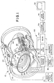
- the apparatus includes a main magnetic field means 10 which generates a substantially uniform magnetic field longitudinally through an examination region 12.
- the main magnetic field means includes a plurality of main field magnets 14 which are operated under control of a magnetic field control means and power supply 16.
- the main magnetic field is a strong, uniform field that is aligned with a z or longitudinal axis.
- An elliptical gradient magnetic field means 20 selectively creates gradient magnetic fields across the examination region 12.
- the gradient field means includes a z-gradient coil assembly 22 which applies or creates magnetic field gradients along the z-axis.
- An x-gradient coil assembly 24 selectively applies or creates magnetic field gradients in an x direction transverse to the z-axis and along the major axis of the elliptical gradient magnetic field means in the illustrated embodiment.
- a y-gradient coil assembly 26 ( Figure 3) selectively applies or causes magnetic field gradients in a y direction, transverse to the x and z-axes and along the minor of the ellipse.
- Each of the x, y, and z-gradient coil assemblies include a plurality of symmetrically arranged windings or coil loops.
- a current control means 28 selectively supplies electrical current to each loop of the x, y, and z-gradient coils. The current is supplied to the current loops such that the current flows through some of the loops of each coil assembly in a first or clockwise direction and through other loops of the same assembly in an opposite or counterclockwise direction.
- a gradient field control means 39 controls the current control means 28 to cause it to apply appropriate current pulses to the gradient field windings to cause selected gradient pulses.
- a resonance excitation means includes a radio frequency transmitter 42 for generating radio frequency pulses of the appropriate frequency spectrum for inducing resonance in selected dipoles disposed in the examination region.
- the radio frequency transmitter is connected to a radio frequency antenna 44 disposed adjacent the examination region for transmitting radio frequency pulses into a region of interest of the patient or other subject in the examination region.
- the radio frequency antenna is illustrated as being disposed peripherally around the gradient coil assemblies, it is to be appreciated that such antenna may also be disposed within the gradient coil assemblies.
- a surface coil may be positioned contiguous to an examined patient or subject for controllably inducing magnetic resonance in a selected contiguous region of the patient.
- a magnetic resonance receiving means 50 includes the radio frequency coil 44 which receives, as well as transmits, radio frequency signals in the illustrated embodiment. For other studies, separate transmit and receive coils are used. For example, receive only surface coils may be disposed contiguous to a selected region of the patient to receive resonance signals induced by the radio frequency coil 44 .
- a radio frequency receiver 52 receives the radio frequency signals from the antenna 44 . The received radio frequency signals are demodulated and reconstructed into an image representation. More specifically, a Fourier transform means 54 performs an inverse two-dimensional fast Fourier transform on the magnetic resonance signals to transform them into an image representation for storage in an image memory means 56 .
- the image may represent a planar slice through the patient, an array of parallel planar slices, a three dimensional volume, or the like.
- a display means 58 such as a video monitor, provides a man-readable display of the resultant image.
- Other conventional processing equipment which is conventional in the art, is omitted from the illustration for simplicity.
- the elliptical gradient coil 20 in the preferred embodiment, includes two elliptical formers 60 , 62 made of a non-magnetic and non-conducting material.
- the two elliptical formers or sleeves are configured relative to each other such that they nest snugly together.
- Two of the coils are formed on opposite surfaces of the same elliptical cylinder or former and the third coil is formed on the other. Alternately, one of the surfaces may be covered with a smooth insulator and the third coil formed on that.
- the energy stored in the coil in joules is 0.74 joules for the circle, 0.49 joules for an ellipse with a major axis 2a of 55 centimeters and a minor axis 2b of 45 centimeters, and only 0.41 joules for an elliptical cross-section with a major axis of 55 centimeters and a minor axis of 40 centimeters.
- the stored energy increases.
- the ellipse with the 45 centimeter minor axis stores 19% less energy than the circular cross-section coil and the 40 centimeter minor axis ellipse cross-section coil stores 36% less energy than the circular cross-section coil.
- ⁇ j are the solved for Lagrange multipliers
- B z (x i , y i , z i ) is the magnetic flux density at points x i , y i , z i
- W m is the stored magnetic energy
- J(k2) is the Fourier transform of the current density J (z).
- an x-y plane of symmetry 70 marks the center of the z-gradient coil 22 .
- Loops of the z-gradient coil are distributed along the elliptical surface from the central plane 70 to edge loops 72 , 72 '. The exact number of loops will vary with the precision to which equations (1) - (5) are solved. Twenty-four loops to either side of the symmetric plane are used in the illustrated embodiment. More specifically, in a first four loop array 74 on one side of the symmetric plane, current flows in first direction. In a mirror image four loop array 74 ', which is mirror imaged to the other side of the symmetric plane, current flows in an opposite, second direction.
- a third loop array 76 adjacent the first loop array 74 the current flows in the second direction, i.e. contrary to the neighboring first four loop array 74 .
- a fourth loop array 76 ' has current that flows in the first direction, i.e. opposite to the second loop array 76 '.
- the current flows in the first direction, i.e. the same as in the first loop array 74 .
- the current flows in the second direction, i.e. the same as the second loop array and opposite to the fourth loop array.
- each current loop receives the same amount of current from the current control 28 and the spacing between the loops is adjusted to provide a current density dictated by solving equations (1) - (5).
- the loops may have a constant spacing and different current magnitudes to achieve the same identified current densities.
- Coils in the x and y direction are again determined by solving equations analogous to equations (1) - (5) but with different constraints, i.e. a linearly changing gradient in the x or y direction, respectively, and constant in the other directions.
- the y-gradient coil is again symmetric about the plane of symmetry 70 and about a y-z plane.
- a first loop array 80 and a second loop arrangement 80 ' are disposed symmetrically about the plane of symmetry.
- Third and fourth coil loops arrays 82 and 82 ' are also disposed symmetrically about the plane of symmetry.
- the first and second coil loop arrays correct for irregularities in the gradient generated by the third and fourth loop arrays, respectively.
- Additional loop arrays can be disposed symmetrically about the plane of symmetry to provide second and higher order corrections.
- the current control means 28 applies electrical currents to the coils such that the current in the first and second coil loop arrays is in the opposite directions, e.g. first and second directions.
- the current control means further applies currents to the third and fourth coil arrays such that the current flows in opposite directions relative to each other and in an opposite direction relative to the closest one of the first and second coil loop arrays.
- the first coil loop array has a first direction current
- the second and third coil loop arrays have second direction currents
- the fourth coil loop array has first direction current.
- a like set of y-gradient coil arrays is disposed on the opposite side of the elliptical former mirror imaged about an x-z plane.
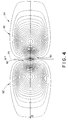
- FIGURE 4 illustrates an exemplary coil winding pattern for the x-gradient.
- the x-gradient coil is again wrapped around and on the surface of one of the elliptical formers.
- the x-gradient coil again has first and second coil loop arrays 90, 90' that are disposed symmetrically to either side of the plane of symmetry 70 and about the x-z plane.
- Third and fourth coil arrays 92, 92' are disposed symmetric to the plane of symmetry and the x-z plane.
- the first and second coil arrays which are smaller and closer to the plane of symmetry than the third and fourth coil loop arrays correct for non-linearities in the gradient generated by the third and fourth coil arrays, respectively.
- a like set of four coil arrays is disposed on an opposite side of the major axis of the ellipse mirror image about the y-z plane.
Landscapes
- Physics & Mathematics (AREA)
- Condensed Matter Physics & Semiconductors (AREA)
- General Physics & Mathematics (AREA)
- Magnetic Resonance Imaging Apparatus (AREA)
Applications Claiming Priority (2)
| Application Number | Priority Date | Filing Date | Title |
|---|---|---|---|
| US07/719,334 US5177441A (en) | 1989-06-16 | 1991-06-21 | Elliptical cross section gradient oil |
| US719334 | 1991-06-21 |
Publications (2)
| Publication Number | Publication Date |
|---|---|
| EP0519637A1 true EP0519637A1 (de) | 1992-12-23 |
| EP0519637B1 EP0519637B1 (de) | 1997-03-26 |
Family
ID=24889665
Family Applications (1)
| Application Number | Title | Priority Date | Filing Date |
|---|---|---|---|
| EP92305317A Expired - Lifetime EP0519637B1 (de) | 1991-06-21 | 1992-06-10 | Apparat mittels magnetischer Resonanz |
Country Status (4)
| Country | Link |
|---|---|
| US (1) | US5177441A (de) |
| EP (1) | EP0519637B1 (de) |
| JP (1) | JPH05269100A (de) |
| DE (1) | DE69218500T2 (de) |
Families Citing this family (19)
| Publication number | Priority date | Publication date | Assignee | Title |
|---|---|---|---|---|
| US5424643A (en) * | 1989-06-16 | 1995-06-13 | Picker International, Inc. | Magnetic resonance gradient sheet coils |
| EP0560396B1 (de) * | 1992-03-13 | 2001-11-07 | Kabushiki Kaisha Toshiba | Bilderzeugung mittels magnetischer Kernresonanz mit verbesserter Bildqualität und Betriebsweise |
| US5623208A (en) * | 1993-04-14 | 1997-04-22 | Jeol Ltd. | Z-axis magnetic field gradient coil structure for magnetic resonance system |
| GB2295020B (en) * | 1994-11-03 | 1999-05-19 | Elscint Ltd | Modular whole - body gradient coil |
| IT1288452B1 (it) | 1996-11-20 | 1998-09-22 | Esaote Spa | Metodo per migliorare l'efficienza di sistemi di bobine in particolare nei dispositivi di acquisizione di immagini mediante |
| DE19653449C2 (de) * | 1996-12-20 | 1999-11-11 | Siemens Ag | Gradientenspulenanordnung für ein Kernspintomographiegerät |
| US6272370B1 (en) | 1998-08-07 | 2001-08-07 | The Regents Of University Of Minnesota | MR-visible medical device for neurological interventions using nonlinear magnetic stereotaxis and a method imaging |
| US6463317B1 (en) | 1998-05-19 | 2002-10-08 | Regents Of The University Of Minnesota | Device and method for the endovascular treatment of aneurysms |
| GB2337595B (en) * | 1998-05-22 | 2003-03-19 | Oxford Magnet Tech | Improvements in or relating to magnetic resonance imaging systems |
| GB2350682A (en) | 1999-06-04 | 2000-12-06 | Marconi Electronic Syst Ltd | Laterally moveable RF coil for MRI |
| DE19943372C2 (de) | 1999-09-10 | 2001-07-19 | Siemens Ag | Gradientenspulensystem für ein Magnetresonanztomographiegerät |
| JP4421079B2 (ja) | 2000-05-23 | 2010-02-24 | 株式会社東芝 | Mri用傾斜磁場コイル |
| JP4789254B2 (ja) * | 2006-05-01 | 2011-10-12 | 株式会社日立メディコ | 水平静磁場方式の楕円筒状ガントリおよびそれに適合するアクティブシールド型傾斜磁場コイル装置を有する磁気共鳴イメージング装置 |
| JP2010046495A (ja) * | 2009-09-04 | 2010-03-04 | Toshiba Corp | Mri用傾斜磁場コイルの設計方法 |
| CN102665543B (zh) * | 2009-11-27 | 2015-08-26 | 株式会社日立医疗器械 | 倾斜磁场线圈、核磁共振成像装置以及线圈图形的设计方法 |
| JP5685476B2 (ja) * | 2011-04-11 | 2015-03-18 | 株式会社日立製作所 | 磁気共鳴イメージング装置 |
| DE102012221918B3 (de) * | 2012-11-29 | 2014-02-13 | Siemens Aktiengesellschaft | Anordnung zur Erzeugung des Hauptmagnetfeldes und des Gradientenmagnetfeldes einer Magnetresonanztomografieanlage, Magnetresonanztomografieanlage und Verfahren zum Betrieb einer Magnetresonanztomografieanlage |
| JP6146550B2 (ja) * | 2015-02-16 | 2017-06-14 | 株式会社村田製作所 | アンテナ装置および通信端末装置 |
| EP3594707B1 (de) | 2018-07-09 | 2023-06-07 | Esaote S.p.A. | Verfahren zum entwerfen von gradientenspulen für mrt-systeme und mrt-system mit solchen gradientenspulen |
Citations (4)
| Publication number | Priority date | Publication date | Assignee | Title |
|---|---|---|---|---|
| US4820988A (en) * | 1987-10-07 | 1989-04-11 | The Regents Of The University Of California | Magnetic gradient coil set for nuclear magnetic resonace system having substantially different coil-patient spacings |
| JPH0280031A (ja) * | 1988-09-19 | 1990-03-20 | Hitachi Ltd | 核磁気共鳴を用いた検査装置 |
| US4910462A (en) * | 1989-04-28 | 1990-03-20 | General Electric Company | Etched Z-axis gradient coils for NMR system |
| US5012191A (en) * | 1988-11-28 | 1991-04-30 | Siemens Aktiengesellschaft | Gradient coil system for a nuclear magnetic resonance tomography apparatus |
Family Cites Families (13)
| Publication number | Priority date | Publication date | Assignee | Title |
|---|---|---|---|---|
| DE3133933A1 (de) * | 1981-08-27 | 1983-03-17 | Siemens AG, 1000 Berlin und 8000 München | "gradientenspulen-system einer einrichtung der kernspinresonanz-technik" |
| DE3133873A1 (de) * | 1981-08-27 | 1983-03-17 | Siemens AG, 1000 Berlin und 8000 München | Gradientenspulen-system fuer eine einrichtung der kernspinresonanz-technik |
| FI65862C (fi) * | 1982-10-11 | 1984-07-10 | Instrumentarium Oy | Nmr-avbildningsapparat |
| US4617516A (en) * | 1983-09-06 | 1986-10-14 | General Electric Company | Axial magnetic field gradient coil suitable for use with NMR apparatus |
| US4646024A (en) * | 1983-11-02 | 1987-02-24 | General Electric Company | Transverse gradient field coils for nuclear magnetic resonance imaging |
| DE3347597A1 (de) * | 1983-12-30 | 1985-07-18 | Philips Patentverwaltung Gmbh, 2000 Hamburg | Hochfrequenz-spulenanordnung zum erzeugen und/oder empfangen von wechselmagnetfeldern |
| US4740751A (en) * | 1984-08-16 | 1988-04-26 | Picker International, Inc. | Whole body MRI resonator |
| NL8502273A (nl) * | 1985-08-19 | 1987-03-16 | Philips Nv | Magnetisch resonantie apparaat met bird cage r.f. spoel. |
| US4791370A (en) * | 1985-08-23 | 1988-12-13 | Resonex, Inc. | Gradient field structure and method for use with magnetic resonance imaging apparatus |
| GB2180943B (en) * | 1985-09-20 | 1990-07-04 | Nat Res Dev | Magnetic field screens |
| US4737716A (en) * | 1986-02-06 | 1988-04-12 | General Electric Company | Self-shielded gradient coils for nuclear magnetic resonance imaging |
| US4881035A (en) * | 1987-11-24 | 1989-11-14 | Siemens Aktiengesellschaft | Magnetic structural arrangement of an installation for nuclear magnetic resonance tomography with superconducting background field coils and normal-conducting gradient coils |
| US4926125A (en) * | 1988-08-22 | 1990-05-15 | General Electric Company | Surface gradient assembly for high speed nuclear magnetic resonance imaging |
-
1991
- 1991-06-21 US US07/719,334 patent/US5177441A/en not_active Expired - Fee Related
-
1992
- 1992-06-10 EP EP92305317A patent/EP0519637B1/de not_active Expired - Lifetime
- 1992-06-10 DE DE69218500T patent/DE69218500T2/de not_active Expired - Fee Related
- 1992-06-15 JP JP4180467A patent/JPH05269100A/ja active Pending
Patent Citations (4)
| Publication number | Priority date | Publication date | Assignee | Title |
|---|---|---|---|---|
| US4820988A (en) * | 1987-10-07 | 1989-04-11 | The Regents Of The University Of California | Magnetic gradient coil set for nuclear magnetic resonace system having substantially different coil-patient spacings |
| JPH0280031A (ja) * | 1988-09-19 | 1990-03-20 | Hitachi Ltd | 核磁気共鳴を用いた検査装置 |
| US5012191A (en) * | 1988-11-28 | 1991-04-30 | Siemens Aktiengesellschaft | Gradient coil system for a nuclear magnetic resonance tomography apparatus |
| US4910462A (en) * | 1989-04-28 | 1990-03-20 | General Electric Company | Etched Z-axis gradient coils for NMR system |
Also Published As
| Publication number | Publication date |
|---|---|
| US5177441A (en) | 1993-01-05 |
| DE69218500D1 (de) | 1997-04-30 |
| DE69218500T2 (de) | 1997-07-03 |
| JPH05269100A (ja) | 1993-10-19 |
| EP0519637B1 (de) | 1997-03-26 |
Similar Documents
| Publication | Publication Date | Title |
|---|---|---|
| EP0404461B1 (de) | Gradientspulenaufbauten für die Erzeugung von Magnetfeldgradienten über einem Bereich | |
| EP0519637B1 (de) | Apparat mittels magnetischer Resonanz | |
| US5278504A (en) | Gradient coil with off center sweet spot for magnetic resonance imaging | |
| US5952830A (en) | Octapole magnetic resonance gradient coil system with elongate azimuthal gap | |
| EP0216590B1 (de) | Magnetische Abschirmungen | |
| EP0629874B1 (de) | Gradientenspule | |
| EP1725886B1 (de) | Asymmetrische ultrakurze gradientenspule für ein magnetresonanz-abbildungssystem | |
| US6262576B1 (en) | Phased array planar gradient coil set for MRI systems | |
| US6522144B2 (en) | RF shielding method and apparatus for an open MRI system | |
| EP1004890A2 (de) | Abgeschirmte Gradientenspulenanordnung für die Magnetresonanzbildgebung | |
| EP0186998B1 (de) | Magnetsystem | |
| EP1359429A2 (de) | Verfahren und Vorrichtung zur Minimierung der Kopplung zwischen Gradienten- und RF-Spule | |
| US6342787B1 (en) | Real-time multi-axis gradient distortion correction using an interactive shim set | |
| JP2584005B2 (ja) | 磁場勾配コイル装置およびそれを用いる磁気共鳴イメージングシステム | |
| US6278276B1 (en) | Phased array gradient coil set with an off center gradient field sweet spot | |
| US5977771A (en) | Single gradient coil configuration for MRI systems with orthogonal directed magnetic fields | |
| EP1237007A2 (de) | Verfahren und Gerät zur RF-Abschirmung | |
| EP1094330B1 (de) | Vorrichtung für die Bildgebung mit magnetischer Resonanz und Verfahren zur Konstruktion einer Gradientenspuleneinrichtung | |
| US5942898A (en) | Thrust balanced bi-planar gradient set for MRI scanners | |
| US6100692A (en) | Gradient coil set with a finite shield current | |
| US6236203B1 (en) | Super shielding of finite length structures in open magnetic and electric systems | |
| WO1999054747A1 (en) | Magnetic gradient field projection | |
| EP0856743A1 (de) | Reduktion von Wirbelströmen in "Fingerprint"-Gradientenspulen für die bildgebende magnetische Resonanz | |
| US6452393B1 (en) | Nuclear magnetic resonance birdcage coil with Cassinian oval former |
Legal Events
| Date | Code | Title | Description |
|---|---|---|---|
| PUAI | Public reference made under article 153(3) epc to a published international application that has entered the european phase |
Free format text: ORIGINAL CODE: 0009012 |
|
| AK | Designated contracting states |
Kind code of ref document: A1 Designated state(s): DE FR NL |
|
| 17P | Request for examination filed |
Effective date: 19930609 |
|
| 17Q | First examination report despatched |
Effective date: 19951026 |
|
| GRAG | Despatch of communication of intention to grant |
Free format text: ORIGINAL CODE: EPIDOS AGRA |
|
| GRAH | Despatch of communication of intention to grant a patent |
Free format text: ORIGINAL CODE: EPIDOS IGRA |
|
| GRAH | Despatch of communication of intention to grant a patent |
Free format text: ORIGINAL CODE: EPIDOS IGRA |
|
| GRAA | (expected) grant |
Free format text: ORIGINAL CODE: 0009210 |
|
| AK | Designated contracting states |
Kind code of ref document: B1 Designated state(s): DE FR NL |
|
| ET | Fr: translation filed | ||
| REF | Corresponds to: |
Ref document number: 69218500 Country of ref document: DE Date of ref document: 19970430 |
|
| PLBI | Opposition filed |
Free format text: ORIGINAL CODE: 0009260 |
|
| PLBF | Reply of patent proprietor to notice(s) of opposition |
Free format text: ORIGINAL CODE: EPIDOS OBSO |
|
| 26 | Opposition filed |
Opponent name: SIEMENS AG Effective date: 19971223 |
|
| NLR1 | Nl: opposition has been filed with the epo |
Opponent name: SIEMENS AG |
|
| PLBF | Reply of patent proprietor to notice(s) of opposition |
Free format text: ORIGINAL CODE: EPIDOS OBSO |
|
| PLBF | Reply of patent proprietor to notice(s) of opposition |
Free format text: ORIGINAL CODE: EPIDOS OBSO |
|
| PLBO | Opposition rejected |
Free format text: ORIGINAL CODE: EPIDOS REJO |
|
| PLBN | Opposition rejected |
Free format text: ORIGINAL CODE: 0009273 |
|
| STAA | Information on the status of an ep patent application or granted ep patent |
Free format text: STATUS: OPPOSITION REJECTED |
|
| 27O | Opposition rejected |
Effective date: 19990701 |
|
| NLR2 | Nl: decision of opposition | ||
| PGFP | Annual fee paid to national office [announced via postgrant information from national office to epo] |
Ref country code: DE Payment date: 20000605 Year of fee payment: 9 |
|
| PGFP | Annual fee paid to national office [announced via postgrant information from national office to epo] |
Ref country code: FR Payment date: 20000612 Year of fee payment: 9 |
|
| PGFP | Annual fee paid to national office [announced via postgrant information from national office to epo] |
Ref country code: NL Payment date: 20000629 Year of fee payment: 9 |
|
| PG25 | Lapsed in a contracting state [announced via postgrant information from national office to epo] |
Ref country code: NL Free format text: LAPSE BECAUSE OF NON-PAYMENT OF DUE FEES Effective date: 20020101 |
|
| PG25 | Lapsed in a contracting state [announced via postgrant information from national office to epo] |
Ref country code: FR Free format text: LAPSE BECAUSE OF NON-PAYMENT OF DUE FEES Effective date: 20020228 |
|
| NLV4 | Nl: lapsed or anulled due to non-payment of the annual fee |
Effective date: 20020101 |
|
| PG25 | Lapsed in a contracting state [announced via postgrant information from national office to epo] |
Ref country code: DE Free format text: LAPSE BECAUSE OF NON-PAYMENT OF DUE FEES Effective date: 20020403 |