EP0519666A2 - Système d'enroulement d'un matériau en bande - Google Patents
Système d'enroulement d'un matériau en bande Download PDFInfo
- Publication number
- EP0519666A2 EP0519666A2 EP92305472A EP92305472A EP0519666A2 EP 0519666 A2 EP0519666 A2 EP 0519666A2 EP 92305472 A EP92305472 A EP 92305472A EP 92305472 A EP92305472 A EP 92305472A EP 0519666 A2 EP0519666 A2 EP 0519666A2
- Authority
- EP
- European Patent Office
- Prior art keywords
- shaft
- take
- winding
- belt material
- engagement
- Prior art date
- Legal status (The legal status is an assumption and is not a legal conclusion. Google has not performed a legal analysis and makes no representation as to the accuracy of the status listed.)
- Withdrawn
Links
Images



Classifications
-
- B—PERFORMING OPERATIONS; TRANSPORTING
- B65—CONVEYING; PACKING; STORING; HANDLING THIN OR FILAMENTARY MATERIAL
- B65H—HANDLING THIN OR FILAMENTARY MATERIAL, e.g. SHEETS, WEBS, CABLES
- B65H19/00—Changing the web roll
- B65H19/22—Changing the web roll in winding mechanisms or in connection with winding operations
- B65H19/30—Lifting, transporting, or removing the web roll; Inserting core
-
- B—PERFORMING OPERATIONS; TRANSPORTING
- B65—CONVEYING; PACKING; STORING; HANDLING THIN OR FILAMENTARY MATERIAL
- B65H—HANDLING THIN OR FILAMENTARY MATERIAL, e.g. SHEETS, WEBS, CABLES
- B65H19/00—Changing the web roll
- B65H19/22—Changing the web roll in winding mechanisms or in connection with winding operations
- B65H19/2207—Changing the web roll in winding mechanisms or in connection with winding operations the web roll being driven by a winding mechanism of the centre or core drive type
-
- B—PERFORMING OPERATIONS; TRANSPORTING
- B65—CONVEYING; PACKING; STORING; HANDLING THIN OR FILAMENTARY MATERIAL
- B65H—HANDLING THIN OR FILAMENTARY MATERIAL, e.g. SHEETS, WEBS, CABLES
- B65H39/00—Associating, collating, or gathering articles or webs
- B65H39/16—Associating two or more webs
-
- B—PERFORMING OPERATIONS; TRANSPORTING
- B65—CONVEYING; PACKING; STORING; HANDLING THIN OR FILAMENTARY MATERIAL
- B65H—HANDLING THIN OR FILAMENTARY MATERIAL, e.g. SHEETS, WEBS, CABLES
- B65H2301/00—Handling processes for sheets or webs
- B65H2301/40—Type of handling process
- B65H2301/41—Winding, unwinding
- B65H2301/417—Handling or changing web rolls
- B65H2301/4171—Handling web roll
- B65H2301/41745—Handling web roll by axial movement of roll
-
- B—PERFORMING OPERATIONS; TRANSPORTING
- B65—CONVEYING; PACKING; STORING; HANDLING THIN OR FILAMENTARY MATERIAL
- B65H—HANDLING THIN OR FILAMENTARY MATERIAL, e.g. SHEETS, WEBS, CABLES
- B65H2405/00—Parts for holding the handled material
- B65H2405/40—Holders, supports for rolls
- B65H2405/42—Supports for rolls fully removable from the handling machine
- B65H2405/422—Trolley, cart, i.e. support movable on floor
-
- B—PERFORMING OPERATIONS; TRANSPORTING
- B65—CONVEYING; PACKING; STORING; HANDLING THIN OR FILAMENTARY MATERIAL
- B65H—HANDLING THIN OR FILAMENTARY MATERIAL, e.g. SHEETS, WEBS, CABLES
- B65H2801/00—Application field
- B65H2801/93—Tyres
Definitions
- This invention relates to a winding system for winding up onto a take-up shaft of a long length of a soft belt material which is, for example, the material for the tread or side walls of a tyre.
- FIG. 10 of the accompanying drawings is a schematic side view showing one example of a conventional winding system for the aforesaid purpose.
- a belt material 01 is fed by means of a front conveyor 03 to a take-up shaft and is wound onto the latter.
- the belt material 01 fed out of a front end portion of the conveyor 03, passes a dancer roller 04 before reaching the take-up shaft 02 and is wound up onto the take-up shaft while being kept under a certain tension resulting from the setting of the dancer roller 04 under which it passed.
- a liner 07 is fed from a liner supply roll 05 over rolls 06 and is wound onto the take-up shaft 02 together with the belt material 01.
- the take-up shaft 02 is mounted on a platform car (not shown). As the platform car travels along a predetermined path, the take-up shaft 02 is conveyed to a predetermined position where a winding drive shaft is disposed. Rotation is then transmitted to the take-up shaft 02 from the winding drive shaft to perform the required winding operation. When the winding operation is over, the platform car moves back along the predetermined path, its use alternating with the use of another platform car.
- the dancer roller 04 In starting the take-up of the belt material 01 onto the take-up shaft 02, the dancer roller 04 is in a raised position so as not to operate, and, as shown in Figure 11, the leading end 01a of the belt material 01 hangs down from the front conveyor 03 and is fed to the take-up shaft 02 from above. Therefore, when the front end 01a makes contact with the take-up shaft 02, it may be bent in a direction opposite to the direction of rotation and wound up onto the take-up shaft, as shown in Figure 12.
- a winding system for winding onto a take-up shaft a long length of belt material which is being supplied continuously, the winding system including guide means for guiding leading and trailing ends of the belt material each up to a predetermined position on the take-up shaft, and a dancer roller for acting on the belt material to impart a predetermined tension to it while it is being wound onto the take-up shaft.
- the guide means guides both the leading and trailing ends of the belt material up to a predetermined position on the take-up shaft, there is no fear of the two ends being bent when wound up onto the take-up shaft.
- a winding system further including: a winding drive shaft for winding onto a take-up shaft a long length of belt material which is being fed continuously, the winding system being characterized by; a winding drive shaft adapted to engage and drive said take-up shaft; a plurality of platform cars each provided with a said take-up shaft and capable of travelling to a position at which engagement with said winding drive shaft can occur and onward from said position when said engagement is terminated; and a retraction means which is operable to achieve said engagement and to achieve termination of engagement when one platform car is to be replaced in engagement with the winding drive shaft by another platform car, which retraction means functions to retract said winding drive shaft in a direction at right angles to the direction of travel of the platform car to be replaced.
- the platform car can move ahead after the winding operation and does not need to move back because the winding drive shaft is retracted, the next platform car is able to enter the winding position immediately. Thus, it is possible to effect efficiently change of platform cars.
- FIG. 1 is a side view of a winding system 1 embodying the invention, shown in its entirety,
- a pair of support posts 2 is erected side by side transverse to the general feed direction of belt material.
- To the upper end of each support post 2 is fixed a horizontal member 3, and a conveyor device 4 is connected to the left end portions of the horizontal members 3 as viewed perpendicularly to the plane of the page.
- a conveyor belt 8 is carried by rollers 5 disposed at predetermined positions of the conveyor device 4 and by rollers 6 and 7 mounted at the upper positions on the support posts 2, undergoing reversal of direction at roller 6.
- a belt material 9 made of rubber is conveyed by the conveyor belt 8.
- the horizontal members 3 are each provided with a photosensor 10 adjacent the roller 6 to detect leading and trailing ends of the belt material 9 fed by the conveying device 4.
- the front and rear support posts 2 are each provided with a bearing 15 at an elevated position and with a rotatable shaft 16 supported by the bearings 15. Carried on the rotatable shaft 16 is the base end of a dancer roller member 17, which swings as the rotatable shaft 16 rotates. The dancer roller member terminates in a free end portion which hangs down and supports a dancer roller 18 rotatable thereon.
- a lifter member 30 which projects to the right and obliquely upwardly insofar as the plane of the paper is concerned.
- the lifter member 30 is connected to the upper end of an upwardly projecting cylinder rod of a lifting cylinder 32 which is supported by a bracket 31. Upon operation of the lifting cylinder 32, the lifter member 30 moves vertically.
- a long guide member 33 is attached to the lifter member 30 along the upper surface of the latter, and an advancing cylinder 34 is provided along the guide member 33.
- a guide belt conveyor 35 which is capable of advancing leftwards in the figure along the upper surface of the lifter member 30 while being guided by the guide member 33.
- the front end of the cylinder rod of the advancing cylinder 34 is connected to a lateral position on the guide belt conveyor 35 at a position near a front end of the conveyor projecting from the guide member 33. Therefore, the guide belt conveyor 35 can be moved forwards and backwards by means of the cylinder 34.
- the guide belt conveyor 35 has a belt conveyor which is driven by means of an air motor (not shown).
- the speed of the belt conveyor can be set higher or lower than the conveying speed of the conveyor device 4.
- the guide belt conveyor 35 is moved vertically in a tilted state by means of the lifting cylinder 32, is moved forwards and backwards by the advancing cylinder 34, and drives the conveyor belt by itself using the aforesaid air motor.
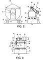
- a winding drive unit 40 As shown in Figures 2 and 3, rails 42 are laid longitudinally on a base 41, and a support frame 44 is supported by the rails 42 to be slidable in a linear direction by means of sliders 43 engaging the rails 42.
- a cylinder 45 is attached to the base 41, the cylinder housing a cylinder rod whose front end is secured to the support frame 44.
- the support frame 44 is made to slide on rails 42 upon operation of the cylinder 45.
- a motor 46 is mounted on the top of the support frame 44, and a drive shaft comprised thereby is connected to the input shaft of a reduction unit 48 through a coupling 47.
- a sprocket 49 is fitted on the output shaft of the reduction unit 48.
- Bearing supports 50 project at front and rear positions from one side face of the support frame 44, and a rotatable shaft 51 is supported rotatably by the bearing supports 50.
- This rotatable shaft 51 projects forward from the frame 44 to form a winding drive shaft 52, with a connecting member 52a being formed at a front end of the shaft 52.
- a continuous chain 54 is stretched between a sprocket 53 fitted on the rotatable shaft 51 and sprocket 49.
- the winding drive shaft 52 is rotated by the motor 46 and is moved back and forth together with the support frame 44 under the action of the cylinder 45.
- a platform car 60 can travel back and forth, right- and leftwards as shown in Figure 1, in front of the winding drive unit 40.
- a take-up shaft 61 is rotatably supported on the platform car 60.
- rails 62 are laid in the transverse direction, and a support member 64 for the platform car 60 is mounted on the rails 62 through wheels 63 so that it can travel back and forth on the rails.
- the take-up shaft 61 is mounted rotatably transversely of the support member 64.
- a connecting member 61a formed at one end of the take-up shaft 61 engages the connecting member 52a formed on the winding drive shaft 52 of the winding drive unit 40.
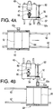
- the platform car 60 is shown positioned for movement left to right to reach a position located in front of the winding drive unit 40 and to stop when the take-up shaft arrives at a position opposed to the winding drive shaft 52. Then, the support frame 44 of the winding drive unit 40 is driven by the cylinder 45 and moves forward, so that the connecting member 52a of the winding drive shaft 52 comes into engagement with the connecting member 61a of the take-up shaft 61 provided on the side of the platform car 60 (see Figure 4B).
- liner 72 is fed from a liner roll 70 through rollers 71 and is wound together with the belt material 9.
- the cylinder 45 When winding of the belt material 9 is over, the cylinder 45 is operated and the winding drive shaft 52 retracted backward to disconnect the shaft 52 and the take-up shaft 61 from each other. Then, the platform car 60 travels on (to the right in Figure 1) and the next platform car is brought in from the left.
- the travel path of the platform car 60 is in one direction only, coming in from the left-hand side and going out to the right after the end of the winding operation. Unlike with the prior art arrangements, therefore, it is not necessary for a preceding platform car to undergo return travel after a winding operation and for the next platform car to wait until the preceding platform car is removed. A change of platform cars can be made efficiently.
- the guide belt conveyor 35 Before the belt material 9 is fed by the conveyor device 4, the guide belt conveyor 35 is in its raised and retracted position, and the front end thereof is positioned just under the roller 6.
- the dancer roller 18 is in its raised position.
- the photosensor 10 disposed near the roller 6 detects the passage of the leading end of the belt material, and causes the belt of the guide belt conveyor 35 to be driven and the leading end of the belt material 9 hanging down from the roller 6 to be received by the belt.
- the leading end, indicated at 9a, of the belt material 9 received by the conveyor 35 is pulled in the conveying direction of the conveyor 35 ( Figure 5).
- the guide belt conveyor 35 descends so that it extends towards the take-up shaft 61 (of a take-up car 61) to guide the leading end 9a of the belt material 9 to a predetermined loading position on the take-up shaft 61 and load it onto the shaft when it is at that position ( Figure 6).
- the leading end 9a of the belt material 9 can be loaded onto the take-up shaft 61 in an optimum position which does not cause bending of the leading end, thereby obviating the foregoing problem of bending of the leading end.
- the belt material 9 is taken up on shaft 61 together with the liner 72.
- the guide belt conveyor 35 stops the movement of its belt and retreats, then the dancer roller member 17 swings downwards, and the dancer roller 18 presses the section of belt material 9 present between the take-up shaft 61 and the roller 6 to impose a certain tension on the belt material.
- the belt material 9 is wound up onto the take-up shaft 61 ( Figures 7 and 8) while under this tension.
- the dancer roller 18 When the photosensor 10 detects the trailing end 9b of the belt material 9, the dancer roller 18 is raised and the guide belt conveyor 35 moves to receive the trailing end 9b of the belt material. After receiving the trailing end 9b, the belt conveyor 35 supports and guides the trailing end 9b up to a predetermined position on the take-up shaft 61 ( Figure 9). At this time, the belt of the guide belt conveyor 35 is driven at low speed to maintain the tension imposed on the belt material 9.
- the guide belt conveyor 35 guides the trailing end 9b of the belt material 9 up to an optimum position at which bending of the trailing end 9b does not occur when the trailing end is delivered to the side of the take-up shaft 61, the aforementioned inconvenience caused by bending of the trailing end will not occur.
- the belt material 9 is wound up onto the take-up shaft 61 under a constant tension without bending of its leading and trailing ends 9a, 9b.
- the take-up operation is repeated on every entry of a platform car, and since each platform car travels only in one direction, it is possible to effect the change of platform cars efficiently.
Landscapes
- Replacement Of Web Rolls (AREA)
- Controlling Rewinding, Feeding, Winding, Or Abnormalities Of Webs (AREA)
- Tyre Moulding (AREA)
Applications Claiming Priority (2)
| Application Number | Priority Date | Filing Date | Title |
|---|---|---|---|
| JP171816/91 | 1991-06-18 | ||
| JP3171816A JPH04371441A (ja) | 1991-06-18 | 1991-06-18 | 帯状部材の巻取装置 |
Publications (2)
| Publication Number | Publication Date |
|---|---|
| EP0519666A2 true EP0519666A2 (fr) | 1992-12-23 |
| EP0519666A3 EP0519666A3 (en) | 1993-05-12 |
Family
ID=15930269
Family Applications (1)
| Application Number | Title | Priority Date | Filing Date |
|---|---|---|---|
| EP19920305472 Withdrawn EP0519666A3 (en) | 1991-06-18 | 1992-06-15 | Belt material winding system |
Country Status (3)
| Country | Link |
|---|---|
| US (1) | US5282584A (fr) |
| EP (1) | EP0519666A3 (fr) |
| JP (1) | JPH04371441A (fr) |
Cited By (6)
| Publication number | Priority date | Publication date | Assignee | Title |
|---|---|---|---|---|
| EP0718227A1 (fr) * | 1994-12-22 | 1996-06-26 | Societe D'etude De Machines Pour Les Arts Graphiques | Dispositif de mise en place et de raccordement de rouleaux de feuilles de papier et analogue |
| EP0741103A3 (fr) * | 1995-05-05 | 1997-10-15 | Wifag Maschf | Dispositif pour transférer le début d'une bande de matériau dans une rotative |
| EP1038814A3 (fr) * | 1999-03-23 | 2002-01-02 | Menzolit-Fibron GmbH | Système d'enroulage pour des bandes d'une composition duroplastique |
| EP1059255A3 (fr) * | 1999-06-08 | 2004-04-14 | Bridgestone Corporation | Dispositif et méthode pour le stockage d'un élément allongé sujet à déformation plastique |
| CN101817460A (zh) * | 2010-04-27 | 2010-09-01 | 双钱集团(重庆)轮胎有限公司 | 重绕机 |
| CN110104477A (zh) * | 2019-06-19 | 2019-08-09 | 无锡山藤精密科技有限公司 | 用于载带自动绕卷收料系统的载带头端夹送机构 |
Families Citing this family (11)
| Publication number | Priority date | Publication date | Assignee | Title |
|---|---|---|---|---|
| US5435501A (en) * | 1993-09-07 | 1995-07-25 | Alexander, Iii; William J. | Center wind takeup drive and method |
| US5470030A (en) * | 1993-12-17 | 1995-11-28 | Guilford Mills, Inc. | Fabric take-up frame for a textile fabric producing machine |
| DE29605339U1 (de) * | 1996-03-22 | 1996-06-05 | Lindauer Dornier Gmbh, 88131 Lindau | Webmaschine mit Warenwickler-Transportwagen |
| US6536702B1 (en) * | 1998-06-10 | 2003-03-25 | The Goodyear Tire And Rubber Company | Surface winding on an a-frame winder |
| KR100318208B1 (ko) * | 2000-01-27 | 2001-12-24 | 임성호 | 포장용 밴드 와인더 |
| US6402077B1 (en) | 2001-02-14 | 2002-06-11 | The Goodyear Tire & Rubber Company | Winder with variable tension zones |
| WO2011073795A1 (fr) | 2009-12-18 | 2011-06-23 | Pirelli Tyre S.P.A. | Procédé et appareil de contrôle de l'enroulement d'un élément allongé sur une bobine de collecte avec interposition d'un tissu de service |
| JP6378581B2 (ja) * | 2014-08-27 | 2018-08-22 | 住友ゴム工業株式会社 | タイヤ構成部材の巻取り方法 |
| JP6654093B2 (ja) * | 2016-04-27 | 2020-02-26 | Toyo Tire株式会社 | トッピングシートの形成方法及び装置 |
| NL2018889B1 (en) * | 2017-05-10 | 2018-11-15 | Vmi Holland Bv | Wind-up system and method for winding-up a strip |
| JP7675734B2 (ja) * | 2021-05-27 | 2025-05-13 | ヴェーエムイー ホーランド ベー. ヴェー. | ストックリールからタイヤ部品を巻き戻し、前記タイヤ部品を搬送方向に出力するための巻き戻しシステムおよび方法 |
Family Cites Families (9)
| Publication number | Priority date | Publication date | Assignee | Title |
|---|---|---|---|---|
| US1620844A (en) * | 1924-03-27 | 1927-03-15 | Walker Maurice | Spindle carriage and clutch |
| ES400106A1 (es) * | 1971-02-27 | 1975-06-16 | Alberto | Perfeccionamientos en una maquina automatica para formar rollos de tejido en pieza. |
| US4103840A (en) * | 1976-12-14 | 1978-08-01 | Westvaco Corporation | Stretchable material rewinding machine |
| DE3012297A1 (de) * | 1980-03-29 | 1981-10-08 | Gebr. Meyer GmbH & Co KG, 5600 Wuppertal | Maschine zur herstellung von bandrollen |
| US4489900A (en) * | 1983-08-01 | 1984-12-25 | Krantz America, Inc. | Apparatus for automatically cutting and winding sheet material |
| US4695005A (en) * | 1985-05-13 | 1987-09-22 | Custom Machinery Design, Inc. | Coreless winder for strips of pliable material |
| US5194107A (en) * | 1987-09-03 | 1993-03-16 | Bridgestone Corporation | Belt-like member attaching method and apparatus |
| US4951892A (en) * | 1988-12-30 | 1990-08-28 | Bridgestone/Firestone, Inc. | Server system for rubberized sheets |
| FI81321C (fi) * | 1989-02-16 | 1990-10-10 | Valmet Oy | Drivenhet foer pappersmaskin eller foer en efterbehandlingsmaskin foer papper och ett hydrauldrivsystem foer denna. |
-
1991
- 1991-06-18 JP JP3171816A patent/JPH04371441A/ja active Pending
-
1992
- 1992-06-10 US US07/896,369 patent/US5282584A/en not_active Expired - Lifetime
- 1992-06-15 EP EP19920305472 patent/EP0519666A3/en not_active Withdrawn
Cited By (8)
| Publication number | Priority date | Publication date | Assignee | Title |
|---|---|---|---|---|
| EP0718227A1 (fr) * | 1994-12-22 | 1996-06-26 | Societe D'etude De Machines Pour Les Arts Graphiques | Dispositif de mise en place et de raccordement de rouleaux de feuilles de papier et analogue |
| FR2728550A1 (fr) * | 1994-12-22 | 1996-06-28 | Sempag Sa | Dispositif de mise en place et de raccordement de rouleaux de feuilles de papier et analogue |
| US5716022A (en) * | 1994-12-22 | 1998-02-10 | Societe D'etude De Machines Pour Les Arts Graphiques | Device for positioning and splicing rolls of paper sheets and the like |
| EP0741103A3 (fr) * | 1995-05-05 | 1997-10-15 | Wifag Maschf | Dispositif pour transférer le début d'une bande de matériau dans une rotative |
| EP1038814A3 (fr) * | 1999-03-23 | 2002-01-02 | Menzolit-Fibron GmbH | Système d'enroulage pour des bandes d'une composition duroplastique |
| EP1059255A3 (fr) * | 1999-06-08 | 2004-04-14 | Bridgestone Corporation | Dispositif et méthode pour le stockage d'un élément allongé sujet à déformation plastique |
| CN101817460A (zh) * | 2010-04-27 | 2010-09-01 | 双钱集团(重庆)轮胎有限公司 | 重绕机 |
| CN110104477A (zh) * | 2019-06-19 | 2019-08-09 | 无锡山藤精密科技有限公司 | 用于载带自动绕卷收料系统的载带头端夹送机构 |
Also Published As
| Publication number | Publication date |
|---|---|
| EP0519666A3 (en) | 1993-05-12 |
| JPH04371441A (ja) | 1992-12-24 |
| US5282584A (en) | 1994-02-01 |
Similar Documents
| Publication | Publication Date | Title |
|---|---|---|
| US5282584A (en) | Belt-like material winding system | |
| CN111702032B (zh) | 一种放卷机构 | |
| US3342014A (en) | Roll wrapper | |
| US4437247A (en) | Apparatus for feeding laundry to an ironing machine | |
| CN214989356U (zh) | 电缆线输送机构 | |
| CN113895895A (zh) | 一种苗床运输用rgv小车及包括该小车的苗床运输线 | |
| US4934621A (en) | Device for continuously feeding a web of material from a stock roll | |
| JP2553992B2 (ja) | 供給物品のアキュームレーション装置 | |
| CN213622018U (zh) | 一种辊床输送线滑撬导偏横移装置 | |
| CN117326370B (zh) | 一种自动卷布机的卷布方法 | |
| CN119429794A (zh) | 用于tpe制品的双工位收卷设备和收卷方法 | |
| CN116534526B (zh) | 一种成像检测型滤网输送设备及其输送方法 | |
| CN114380028B (zh) | 旋转平移装置 | |
| CN117303112A (zh) | 一种智能双盘收线传送系统 | |
| US4614313A (en) | Apparatus for continuously supplying a web of sheet material | |
| CN216188292U (zh) | 多层面片自动搭接输送机 | |
| US3970261A (en) | Handling tire making materials | |
| US4512528A (en) | Device for exchanging a winding mandrel | |
| CN211710089U (zh) | 一种工程胎成型机带束层供料装置 | |
| JP2545331B2 (ja) | スリッタにおける満巻ロ―ル取出し巻芯供給装置 | |
| CN215796434U (zh) | 输送带滚筒包角恒定式带式输送机端部 | |
| KR100349613B1 (ko) | 물품수송설비 | |
| CN214776773U (zh) | 一种水平缠绕机用脱膜输送机构 | |
| JP3032620U (ja) | タイヤ成形機用成形材料供給装置 | |
| CN217195632U (zh) | 一种摆动式海绵块调节导向架 |
Legal Events
| Date | Code | Title | Description |
|---|---|---|---|
| PUAI | Public reference made under article 153(3) epc to a published international application that has entered the european phase |
Free format text: ORIGINAL CODE: 0009012 |
|
| AK | Designated contracting states |
Kind code of ref document: A2 Designated state(s): DE ES FR GB IT |
|
| PUAL | Search report despatched |
Free format text: ORIGINAL CODE: 0009013 |
|
| AK | Designated contracting states |
Kind code of ref document: A3 Designated state(s): DE ES FR GB IT |
|
| 17P | Request for examination filed |
Effective date: 19930827 |
|
| 17Q | First examination report despatched |
Effective date: 19930930 |
|
| STAA | Information on the status of an ep patent application or granted ep patent |
Free format text: STATUS: THE APPLICATION IS DEEMED TO BE WITHDRAWN |
|
| 18D | Application deemed to be withdrawn |
Effective date: 19940823 |