EP0519700A2 - Methode und Gerät zur Versorgung mit phasenwechselnder Tinte in einem Tintenstrahldrucker - Google Patents
Methode und Gerät zur Versorgung mit phasenwechselnder Tinte in einem Tintenstrahldrucker Download PDFInfo
- Publication number
- EP0519700A2 EP0519700A2 EP92305545A EP92305545A EP0519700A2 EP 0519700 A2 EP0519700 A2 EP 0519700A2 EP 92305545 A EP92305545 A EP 92305545A EP 92305545 A EP92305545 A EP 92305545A EP 0519700 A2 EP0519700 A2 EP 0519700A2
- Authority
- EP
- European Patent Office
- Prior art keywords
- ink
- preload
- stick
- chambers
- chamber
- Prior art date
- Legal status (The legal status is an assumption and is not a legal conclusion. Google has not performed a legal analysis and makes no representation as to the accuracy of the status listed.)
- Granted
Links
- 238000000034 method Methods 0.000 title claims description 6
- 230000008859 change Effects 0.000 title description 29
- 230000036316 preload Effects 0.000 claims abstract description 145
- 238000012546 transfer Methods 0.000 claims abstract description 72
- 238000012545 processing Methods 0.000 claims abstract description 22
- 238000004891 communication Methods 0.000 claims abstract description 11
- 238000007639 printing Methods 0.000 claims description 21
- 239000007790 solid phase Substances 0.000 claims description 13
- 238000001514 detection method Methods 0.000 claims description 10
- 230000008569 process Effects 0.000 claims description 2
- 239000003086 colorant Substances 0.000 abstract description 9
- 238000012544 monitoring process Methods 0.000 abstract description 9
- 239000000976 ink Substances 0.000 description 437
- 239000007787 solid Substances 0.000 description 36
- 239000012071 phase Substances 0.000 description 28
- 239000000758 substrate Substances 0.000 description 12
- 239000007788 liquid Substances 0.000 description 11
- 230000008018 melting Effects 0.000 description 9
- 238000002844 melting Methods 0.000 description 9
- 230000003287 optical effect Effects 0.000 description 8
- 239000012943 hotmelt Substances 0.000 description 7
- 230000000712 assembly Effects 0.000 description 6
- 238000000429 assembly Methods 0.000 description 6
- 238000007641 inkjet printing Methods 0.000 description 5
- 238000003780 insertion Methods 0.000 description 5
- 230000037431 insertion Effects 0.000 description 5
- 239000000203 mixture Substances 0.000 description 5
- 230000004044 response Effects 0.000 description 5
- 238000010586 diagram Methods 0.000 description 4
- 230000005484 gravity Effects 0.000 description 4
- 239000007791 liquid phase Substances 0.000 description 4
- LFQSCWFLJHTTHZ-UHFFFAOYSA-N Ethanol Chemical compound CCO LFQSCWFLJHTTHZ-UHFFFAOYSA-N 0.000 description 3
- 239000001993 wax Substances 0.000 description 3
- DLFVBJFMPXGRIB-UHFFFAOYSA-N Acetamide Chemical compound CC(N)=O DLFVBJFMPXGRIB-UHFFFAOYSA-N 0.000 description 2
- 239000004698 Polyethylene Substances 0.000 description 2
- 230000001276 controlling effect Effects 0.000 description 2
- 238000013461 design Methods 0.000 description 2
- 238000010438 heat treatment Methods 0.000 description 2
- 238000003384 imaging method Methods 0.000 description 2
- 239000000155 melt Substances 0.000 description 2
- 238000005192 partition Methods 0.000 description 2
- -1 polyethylene Polymers 0.000 description 2
- 229920000573 polyethylene Polymers 0.000 description 2
- 230000001105 regulatory effect Effects 0.000 description 2
- CXMXRPHRNRROMY-UHFFFAOYSA-N sebacic acid Chemical compound OC(=O)CCCCCCCCC(O)=O CXMXRPHRNRROMY-UHFFFAOYSA-N 0.000 description 2
- 229920000178 Acrylic resin Polymers 0.000 description 1
- 239000004925 Acrylic resin Substances 0.000 description 1
- 239000004215 Carbon black (E152) Substances 0.000 description 1
- 230000005355 Hall effect Effects 0.000 description 1
- 239000002253 acid Substances 0.000 description 1
- 230000009471 action Effects 0.000 description 1
- 230000004913 activation Effects 0.000 description 1
- 150000008431 aliphatic amides Chemical class 0.000 description 1
- 150000008430 aromatic amides Chemical class 0.000 description 1
- 239000004204 candelilla wax Substances 0.000 description 1
- 235000013868 candelilla wax Nutrition 0.000 description 1
- 229940073532 candelilla wax Drugs 0.000 description 1
- 239000004203 carnauba wax Substances 0.000 description 1
- 235000013869 carnauba wax Nutrition 0.000 description 1
- 230000015556 catabolic process Effects 0.000 description 1
- 238000010411 cooking Methods 0.000 description 1
- 238000006731 degradation reaction Methods 0.000 description 1
- 238000011161 development Methods 0.000 description 1
- 150000005690 diesters Chemical class 0.000 description 1
- 235000014113 dietary fatty acids Nutrition 0.000 description 1
- 238000007599 discharging Methods 0.000 description 1
- 238000006073 displacement reaction Methods 0.000 description 1
- 230000008020 evaporation Effects 0.000 description 1
- 238000001704 evaporation Methods 0.000 description 1
- 239000000194 fatty acid Substances 0.000 description 1
- 229930195729 fatty acid Natural products 0.000 description 1
- 150000004665 fatty acids Chemical class 0.000 description 1
- IUJAMGNYPWYUPM-UHFFFAOYSA-N hentriacontane Chemical compound CCCCCCCCCCCCCCCCCCCCCCCCCCCCCCC IUJAMGNYPWYUPM-UHFFFAOYSA-N 0.000 description 1
- 229930195733 hydrocarbon Natural products 0.000 description 1
- 150000002430 hydrocarbons Chemical class 0.000 description 1
- 239000012182 japan wax Substances 0.000 description 1
- 150000002576 ketones Chemical class 0.000 description 1
- 238000012423 maintenance Methods 0.000 description 1
- 239000000463 material Substances 0.000 description 1
- 239000004200 microcrystalline wax Substances 0.000 description 1
- 235000019808 microcrystalline wax Nutrition 0.000 description 1
- 238000013508 migration Methods 0.000 description 1
- 230000005012 migration Effects 0.000 description 1
- 239000003960 organic solvent Substances 0.000 description 1
- 239000012188 paraffin wax Substances 0.000 description 1
- 239000012782 phase change material Substances 0.000 description 1
- 239000000049 pigment Substances 0.000 description 1
- 239000004014 plasticizer Substances 0.000 description 1
- 230000001902 propagating effect Effects 0.000 description 1
- 238000007712 rapid solidification Methods 0.000 description 1
- 239000011347 resin Substances 0.000 description 1
- 229920005989 resin Polymers 0.000 description 1
- 230000000717 retained effect Effects 0.000 description 1
- 238000000926 separation method Methods 0.000 description 1
- 238000001228 spectrum Methods 0.000 description 1
- 238000012360 testing method Methods 0.000 description 1
- 229920001169 thermoplastic Polymers 0.000 description 1
- 229920001187 thermosetting polymer Polymers 0.000 description 1
- 239000004416 thermosoftening plastic Substances 0.000 description 1
- LMYRWZFENFIFIT-UHFFFAOYSA-N toluene-4-sulfonamide Chemical compound CC1=CC=C(S(N)(=O)=O)C=C1 LMYRWZFENFIFIT-UHFFFAOYSA-N 0.000 description 1
- 238000013519 translation Methods 0.000 description 1
- 230000014616 translation Effects 0.000 description 1
Images


Classifications
-
- B—PERFORMING OPERATIONS; TRANSPORTING
- B41—PRINTING; LINING MACHINES; TYPEWRITERS; STAMPS
- B41J—TYPEWRITERS; SELECTIVE PRINTING MECHANISMS, i.e. MECHANISMS PRINTING OTHERWISE THAN FROM A FORME; CORRECTION OF TYPOGRAPHICAL ERRORS
- B41J2/00—Typewriters or selective printing mechanisms characterised by the printing or marking process for which they are designed
- B41J2/005—Typewriters or selective printing mechanisms characterised by the printing or marking process for which they are designed characterised by bringing liquid or particles selectively into contact with a printing material
- B41J2/01—Ink jet
- B41J2/17—Ink jet characterised by ink handling
- B41J2/175—Ink supply systems ; Circuit parts therefor
- B41J2/17593—Supplying ink in a solid state
Definitions
- the present invention relates to methods and apparatus for providing a substantially continuous supply of phase change ink to an ink jet print head.
- Ink jet printers operate by ejecting ink onto a print substrate, such as paper, in controlled patterns of closely spaced dots. By selectively regulating the pattern of ink droplets, such ink jet printers can be used to produce a wide variety of printed materials, including text, graphics, images, and the like. Moreover, ink jet printers are capable of recording permanent images on a wide variety of substrates, including both light reflective and light transmissive substrates.
- phase change inks typically utilize a variety of inks, including phase change inks, which are often referred to as hot melt inks.
- Phase change inks are solid at ambient temperatures and liquid at the elevated operating temperatures of an ink jet printing device.
- Liquid phase ink jet droplets are ejected from the printing device at an elevated operating temperature and, when the ink droplets contact the surface of a substrate, they rapidly solidify to form the predetermined pattern.
- Phase change ink is advantageous for printing purposes for a variety of reasons. Problems associated with nozzle clogging due to ink evaporation are largely eliminated, thereby improving the reliability of ink jet printing. Because the ink droplets solidify rapidly upon contact with the substrate, migration of ink along the printing medium is greatly reduced and image quality is improved. The nature and rapid solidification of phase change inks moreover permits high quality images to be printed on a wide variety of printing substrates.
- U.S. Patent No. 3,653,932 discloses a low melting point (30°C to 50°C) ink having a base comprising di-esters of sebacic acid.
- U.S. Patent No. 3,715,219 describes low melting point (30°C to 60°C) inks including a paraffin alcohol-based ink.
- One disadvantage of printing with low melting point phase change inks is that they frequently exhibit offset problems. Specifically, when substrates printed with these inks are stacked and stored for subsequent use, the ink adheres to adjacent surfaces, particularly if the printed substrates are exposed to high ambient temperatures.
- U.S. Patent Nos. 4,390,369 and 4,484,948 describe methods for producing monochrome phase change inks that employ a natural wax ink base, such as Japan wax, candelilla wax, and carnauba wax, which are subsequently printed from a drop-on-demand ink jet device at a temperature ranging between 65°C and 75°C.
- U.S. Patent No. 4,659,383 discloses a monochrome ink composition having an ink base including a C20-24 acid or alcohol, a ketone, and an acrylic resin plasticizer. These monochrome ink compositions are not durable and, when printed, may become smudged upon routine handling and folding.
- Japanese Patent Application No. 128,053/78 discloses the use of aliphatic and aromatic amides that are solid at room temperature, such as acetamide, as printing inks.
- U.S. Patent No. 4,684,956 is directed to monochrome phase change inks utilizing synthetic microcrystalline wax (hydrocarbon wax) and microcrystalline polyethylene wax. This molten composition can be applied to a variety of porous and non-porous substrates using drop-on-demand ink jet application techniques.
- phase change ink jet printers are capable of discharging multiple ink colors and providing high quality color images.
- Color ink jet printers typically utilize three base color inks, in addition to black, that are blended together to print a large spectrum of intermediate colors.
- European Patent Application Nos. 0187352 and 0206286 disclose phase change ink jet printing in color.
- the ink bases for these systems include fatty acids, a thermoplastic polyethylene and a phase change material in the first application; and the alcohol portion of a thermosetting resin pair, a mixture of organic solvents (o- and p-toluene sulfonamide) and a dye in the second application.
- phase change inks that are substantially transparent provides improved capability to print images on many types of substrates, including light transmissive substrates.
- Phase change ink compositions disclosed in U.S. Patent 4,899,761 are exemplary.
- Phase change ink is conveniently stored, transported, and introduced into an ink jet printer assembly in a solid form. Prior to printing, the ink is heated to a suitable liquid phase temperature. During printer operation, liquid phase ink is supplied to the print head at the proper temperature for ejection. Color ink jet printers use at least one reservoir corresponding to each such color and separate ink jets are in communication with each reservoir for printing the various ink colors. An important consideration in the design of phase change ink jet printers is providing a substantially continuous supply of liquid ink at the ink jet print head from solid ink supply means.
- phase change ink delivery system requiring minimal operator intervention.
- ink color is provided to each such reservoir and the associated jets. This requires alert operator handling as well as reliable mechanical registration systems to assure that appropriate ink colors remain segregated.
- phase change inks also poses challenges to providing a continual supply of phase change ink in the liquid state. It is generally undesirable to heat a large supply of phase change ink or to maintain phase change ink in a liquid state for extended periods of time because extended "cooking" of such inks frequently results in degradation of the ink. Heating of phase change inks is therefore carefully regulated and ink is typically permitted to cool and solidify when the printer is shut off or has been inactive for a predetermined period of time.
- U.S. Patent 4,682,185 teaches a spooled, flexible web of hot melt ink that is incrementally unwound and advanced to a heater location.
- U.S. Patent 4,682,187 teaches delivery of particulate hot melt ink to a melt chamber. Vibration aids gravity feeding of the particulate ink, and the melted ink level, as measured by a float valve, governs introduction of additional ink particulates to the melt chamber.
- U.S. Patent 4,609,924 teaches a solid state ink storage means and buffer reservoir that are fixed relative to the ink reservoir located in the scanning print head.
- the buffer reservoir provides melted ink to the scanning print head on a standby basis.
- U.S. Patent 4,870,430 teaches a solid ink delivery system that selectively supplies individual sticks of solid ink to a hot melt ink jet printer head for melting and subsequent printing.
- Separate ink delivery systems including separately triggerable ink stick feed assemblies, are provided for each color ink stick delivered to the hot melt ink jet printer.
- a positioning assembly is provided for aligning the reservoir openings in the print head with the corresponding ink stick feed assemblies.
- Each ink delivery system furthermore has a registration assembly that prevents triggering of the feed assembly unless the appropriate reservoir opening is properly aligned.
- PCT International Publication No. WO 88/08514 teaches a hot melt ink supply system for an ink jet apparatus adapted for use with multiple pigmented inks.
- Ink is maintained in a liquid condition in two reservoirs: one reservoir is in communication with the ink jet head; and another is a remote supply reservoir.
- the two liquid ink reservoirs communicate through a flexible supply conduit in which ink is normally maintained in a solid condition.
- the supply conduit is heated to melt the ink in the conduit and a pump is actuated to transfer ink in a liquid condition.
- Heaters may be arranged in the ink supply system to maintain thermal gradients and produce convective circulation of molten ink to prevent ink pigments from settling.
- PCT International Publication No. WO 89/02575 teaches a hot melt ink supply unit that utilizes a different keyed configuration for each ink color.
- Ink reservoirs may be formed for each ink color having correspondingly keyed configurations to prevent the possibility of supplying ink of the wrong color to a reservoir reserved for a specific ink color.
- Solid ink blocks and corresponding reservoirs are configured so that ink blocks having a specific configuration can be received only in reservoirs having that configuration.
- European Patent Publication No. 0178886 teaches a solid state ink delivery system wherein solid state ink is stored at a fixed location.
- a movable imaging head has at least one ink jet and an associated reservoir and may be aligned with the solid ink storage reservoir for transferring ink. Ink transfer is accomplished by melting the ink to a liquid state and permitting it to flow into the imaging head reservoir.
- U.S. Patent 4,490,731 teaches an ink dispensing system for a thermal ink jet printer wherein a resistance heating wire traverses the solid ink reservoir and a supply tube connecting the solid ink reservoir with the ink head reservoir. Melted ink is transported through the supply tube by capillary action.
- phase change ink delivery systems in general, have failed to provide the desired substantially continuous ink flow with a minimum of operator handling requirements and mechanical failures.
- Ink delivery systems for supplying solid sticks of phase change ink such as that taught in U.S. Patent 4,870,430, described above, are typically complex and require frequent and alert operator intervention.
- the ink delivery system of the present invention was therefore designed to provide a substantially continuous supply of different types (e.g. , colors) of phase change ink to corresponding print head reservoirs while requiring minimal operator handling and reducing the risks of mechanical failure and operator error.
- the phase change ink delivery system of the present invention provides a substantially continuous supply of ink to a print head for printing.
- the delivery system permits an untrained operator to safely load ink without inadvertently interchanging different types (e.g. colors) of ink, and without inadvertently overfilling any of the ink reservoirs.
- a single triggerable ink transfer system simultaneously transfers ink from a plurality of preload chambers to the corresponding load chambers and ink reservoirs.
- the ink delivery system also includes a processing unit in communication with an operator interface unit that provides ink loading instructions to the operator.
- the processing unit is in communication with sensors that monitor ink loading conditions and ink levels in the print head ink reservoirs and preload chambers. Preferred systems for operating the monitoring and control features of the processing unit are also disclosed.
- the ink delivery system of the present invention is adapted for use with an ink jet printing device utilizing a plurality of inks having different characteristics.
- the system is described with reference to a plurality of inks having different color characteristics, but the ink delivery system of the present invention would be suitable for use with inks having other distinctive properties as well.
- Fig. 1 shows a highly schematic diagram of an ink delivery system of the present invention wherein sensors for detecting various ink loading and ink level conditions at an ink delivery preload assembly 30 and a print head carriage assembly 80 are in communication with processing unit 10.
- Processing unit 10 receives sensed information from ink delivery preload assembly 30 and print head carriage assembly 80 and, in accordance with the sensed information, provides information and operator instructions to operator interface module 20.
- processing unit 10 receives and stores information regarding the presence or absence of solid ink sticks in each preload chamber; the level of ink in specific print head ink reservoirs; the position of the ink transfer lever; actuation of the solenoid; and alignment of print head carriage assembly 80 with preload assembly 30. Based upon this information, instructions are conveyed from processing unit 10 to the user interface module 20 to instruct an operator regarding specific ink loading requirements.
- the monitoring and control functions are preferably implemented by microprocessor-based electronics and may be incorporated in the electronics of the print engine board. Additionally, some processing functions may be incorporated in operator interface module 20. For example, operator interface module 20 may be used for input of printer maintenance commands, such as "CLEAN (PRINT) HEAD” and “TEST PRINT.” Additionally, operator interface module 20 may provide storage of all of the user messages and translations of the messages in a variety of languages. It may also control the state of one or more LED's indicating, for example, "POWER,” "ERROR,” or the like.
- Fig. 2 illustrates operator interface module 20 showing an exemplary level of information and instruction.
- a color-coded ink level display is provided for each ink color utilized - e.g. black, magenta, yellow and cyan.
- Ink levels are typically displayed in one of three categories: "FULL” indicating the ink reservoir level is satisfactory; "HALF FULL” indicating one ink stick may be added; and "EMPTY,” indicating that at least one ink stick must be added.
- specific operator instructions are displayed - e.g. "STOPPED - ADD YELLOW INK” - that prompt an operator to perform specific tasks.
- Print head carriage assembly 80 and ink delivery preload assembly 30 are preferably separate and independent units.
- Preload assembly 30 is stationary with respect to print head carriage assembly 80 and is permanently mounted in the ink jet printer.
- Phase change ink is introduced as a solid phase ink stick to preload assembly 30 and is maintained in the solid phase in preload assembly 30.
- Solid ink sticks are transferable from preload assembly 30 to print head carriage assembly 80, where they are melted prior to and during printing operations.
- Print head carriage assembly 80 is alignable with ink preload assembly 30 during transfer of solid ink sticks and ink transfer cannot take place until proper alignment of the print head carriage assembly has been confirmed.
- the printing substrate and print head carriage assembly 80 are typically reciprocated relative to one another during printing operations as liquid phase ink is ejected from the print head carriage assembly.
- ink preload assembly 30 has a plurality of ink preload chambers 32.
- the ink delivery system illustrated and described herein is intended for use with four ink colors, and four ink preload chambers 32(a)-(d) are consequently provided.
- Each preload chamber 32(a)-(d) is physically separated from the other ink preload chambers and is reserved for use with a specific ink color.
- the chambers are preferably generally rectangular and, according to preferred embodiments, each preload chamber 32 is adapted to accommodate a single stick of solid phase ink.
- Ink preload chambers are defined by end walls 33 and 34 and partitions 35, 36 and 37.
- the ink delivery system of the present invention utilizes solid phase ink sticks having a different configuration assigned to each ink color.
- Ink preload chambers 32(a)-(d) are correspondingly keyed for specific ink stick configurations. This is conveniently accomplished by mounting an aperture plate 38 at an upper end of ink preload assembly 30.
- Aperture plate 38 is provided with a series of apertures, shown as 39(a)-(d), in Fig. 4, each having a different configuration.
- Each of the aperture configurations is mutually non-exclusive - that is, each aperture can accommodate ink sticks of only one configuration. This feature assures that appropriate ink sticks are insertable only in the corresponding preload chambers and prevents an operator from inadvertently inserting ink sticks into the wrong preload chamber.
- Aperture plate 38 is preferably mounted in ink preload assembly 30 such that standard ink sticks project from the surface of aperture plate 38 when inserted in the corresponding preload chambers. This feature permits manual removal of an ink stick from a preload chamber if the ink stick was loaded prematurely or in error. As shown in Fig. 3, end wall 33 and partitions 35-37 project above aperture plate 38 to maintain the separation between adjacent preload chambers.
- aperture 39(d) and the corresponding preload chamber 38(d) are larger than their counterparts. Because black is typically the most commonly used ink, a larger ink reservoir may be provided.
- the solid ink preload chamber and aperture provided for black ink are therefore sized to accommodate larger ink sticks and thereby provide a continuous supply of ink to the corresponding ink reservoir.
- Ink preload chambers 32(a)-(d) are coverable at both ends.
- An operator access end of preload chambers 32(a)-(d) is coverable by a cover plate 40 that extends substantially the width of preload assembly 30.
- Cover plate 40 is pivotable about pivot pin(s) 41 and is rotatable to permit insertion of solid ink sticks into the corresponding ink preload chambers.
- Cover plate 40 is preferably spring loaded toward a closed position so that it is automatically maintained in a closed condition except when pivoted by an operator to insert ink into the preload chamber(s).
- Cover plate 40 is also interlocked to preclude ink transfer from a preload chamber to a load chamber or ink reservoir when the cover plate is opened. This feature protects the operator from hazards such as ink splashes.
- Ink sticks 12 are retained in ink preload chambers 32(a)-(d) by means of a movable preload door 42 positionable beneath ink preload chambers 32(a)-(d).
- Preload door 42 includes two end walls 43, one of which is visible in Figs. 5-10. Opposite preload door end walls 43 are mounted for pivotal movement on end walls 33 and 34 of preload chambers 32(a) and 32(d) at pivot point 44.
- An arcuate bottom wall 45 extends between the end walls 43 substantially the width of preload assembly 30 and, when in a closed position, retains ink sticks in chambers 32(a)-(d).
- Pin 46 projects from preload door end wall 43 and is instrumental during adjustment of preload door 42 between closed and ink transfer positions. Upon rotation of preload door 42, ink sticks are transferred by gravity from one or more preload chambers 32(a)-(d) to adjacent load chambers in print head carriage assembly 80.
- Print head carriage assembly 80 includes ink reservoirs 82(a)-(d) corresponding to each ink color and arranged in a fashion corresponding to the arrangement of preload chambers 32(a)-(d). During printing operations, ink is maintained in a liquid condition in ink reservoirs 82(a)-(d) to provide a continuous supply of ink to print heads mounted on exposed face 83 of print head carriage assembly 60. Ink level sensing means 84 are provided in each ink reservoir 82 to continuously monitor ink levels and convey information concerning operating ink levels to processing unit 10.
- print head carriage assembly 80 includes ink load chambers 86(a)-(d) that serve as ink storage and melting chambers intermediate ink preload chambers 32 and corresponding ink reservoirs 82.
- a filter 85 separates ink load chambers 86 from respective ink reservoirs 82 and serves to filter the melted ink before it is deposited in ink reservoirs 82.
- Each ink load chamber 86 has a cross-sectional configuration at least generally coextensive with that of the corresponding ink preload chamber 32. Ink load chambers 86 may, however, be sized to accommodate more than one stick of ink in an end-to-end arrangement.
- Ink load chambers 86(a)-(d) are in communication with corresponding ink reservoirs 82(a)-(d), such as via filter 85, and provide liquid ink to the corresponding ink reservoir. Heaters are typically provided in ink load chambers 86 that are activated to melt ink in the load chambers in response to the presence of solid ink in the load chambers subsequent to their having been loaded from pre-load chambers 32(a)-(d).
- Ink load chambers 86 and ink preload chambers 32 are preferably aligned on a plane that is disposed at an angle with respect to exposed face 83, which forms the mounting plane for the ink jet print heads.
- Ink jet print heads are conventionally arranged to eject ink droplets in a generally horizontal direction and exposed face 83 is thus oriented generally vertically.
- Arrangement of ink preload assembly 30 and ink load chambers 86 in a canted orientation, as shown, enhances visibility and accessibility of preload assembly 30 to operators and facilitates user interface during the insertion or removal of ink sticks. It moreover facilitates the flow of liquid ink between ink load chambers 86 and corresponding ink reservoirs 82 and provides a more compact assembly.
- the angled orientation of ink preload assembly 30 and ink load chambers 86 also provides a continually dry contact surface for solid ink sticks during loading and thereby reduces the likelihood of melted ink splashing during solid ink loading.
- Ink load chambers 86 are coverable by means of a movable load door 90.
- Load door 90 is preferably similar in design to preload door 42 and extends at least substantially the width of carriage assembly 80.
- Load door 90 includes two end walls 91, one of which is visible in Figs. 5-10. End walls 91 are pivotally mounted to end walls of ink load chambers 86 at pivot point 92. An arcuate load door bottom wall 93 extends between end walls 91.
- Pin 94 projects from load door end wall 91 and is instrumental during adjustment of preload door 42 between closed and ink transfer positions.
- Load door 90 is preferably spring biased toward the closed position, so that it is automatically returned to the closed position unless it is held open.
- Each ink preload chamber 32 is provided with an ink sensing device.
- the embodiment illustrated in Figs. 5-10 employs an optical sensing means, but other types of sensors, such as microswitches and the like, are well known and would be suitable.
- the optical sensor preferably comprises means for propagating an optical beam 47, such as an LED (light emitting diode) 48, with a photoresistor 49 mounted opposite the beam and capable of detecting the beam.
- the position of a sensor flag 50 with respect to the optical sensor signals the presence or absence of an ink stick in ink preload chambers 32.
- Optical beam 47 emitted by LED 48 is uninterrupted and detected by photoresistor 49 when the ink preload chamber is empty, as shown in Fig. 5.
- Sensor flag 50 has a projecting portion 51 that projects into the corresponding ink preload chamber 32 when ink is not present in the preload chamber.
- Sensor tripping portion 52 is disposed on the opposite side of sensor flag 50.
- Flag 50 is pivotally mounted intermediate the projecting and sensor tripping portions at pivot point 53.
- sensor flag 50 Upon insertion of ink stick 12 into preload chamber 32, sensor flag 50 is rotated and optical beam 47 is blocked by sensor tripping portion 52.
- Ink stick sensing devices in each ink preload chamber convey signals to processing unit 10 indicating the presence or absence of an ink stick in each preload chamber.
- Preload assembly 30 additionally includes an ink transfer lever 55 pivotally mounted to an extending side wall of ink preload assembly 30.
- Ink transfer lever 55 is movable between a rest position, as shown in Figs. 5 and 6, and an ink preload position, as shown in Figs. 7 and 8.
- Ink transfer lever 55 includes a handle 56 that projects sufficiently above ink preload chambers 32 to be accessible to an operator during ink transfer operations and a projection 57 that provides a detection surface to indicate when ink transfer lever 55 is in an ink preload position.
- Ink transfer slide 58 is mounted in slidable relationship with respect to lever 55.
- Ink transfer slide 58 includes first and second detents 59 and 60, respectively, that are engageable with pins 46 and 94, respectively, provided on end walls of preload and load doors 42 and 90, respectively.
- Ink transfer slide 58 is mounted on an actuatable push rod 62.
- Push rod 62, and hence ink transfer slide 58, are preferably slidable upon activation of solenoid 63.
- Fig. 5 shows the print head carriage assembly and the ink preload assembly aligned in an ink transfer position wherein carriage assembly 80 is aligned underneath preload assembly 30 and corresponding preload and load chambers are in registration. Sensors are provided to detect alignment and communicate with processing unit 10. Suitable sensing means for performing this function are well known in the art. Ink transfer operations cannot be accomplished unless the carriage and preload assemblies are in alignment. Preload and load doors 42 and 90, respectively, are in a closed position.
- Carriage assembly 80 is also automatically aligned with preload assembly 30 in an ink transfer position upon detection of a solid ink stick in any preload chamber 32. Ink transfer operations are therefore commenced by alignment of carriage assembly 80 with preload assembly 30 as the result of an "EMPTY" ink level reading or upon insertion of an ink stick in a preload chamber in response to a "HALF FULL" ink level reading.
- Ink loading operations can be initiated upon alignment of carriage assembly 80 with preload assembly 30.
- cover plate 40 is pivoted about pivot pin(s) 41 to provide access to ink preload chambers 32.
- an operator may insert appropriate ink sticks 12 into appropriate ink chambers in response to the instructions and/or ink level readings provided at user interface module 20.
- solenoid 63 While cover plate 40 is open, power to solenoid 63 is grounded to prevent slide 59 from being moved. This is accomplished by means of a Hall-Effect switch arranged in series with solenoid 63.
- processing unit 10 Upon insertion of an ink stick 12 into the corresponding preload chamber 32, sensor flag 50 obstructs the path of optical beam 47 and an ink detection signal is conveyed to processing unit 10.
- Processing unit 10 confirms that ink reservoir 82 corresponding to the loaded preload chamber 32 has a "HALF FULL” or "EMPTY” ink level reading and therefore can accept loaded ink, and that the carriage-and preload assemblies are in alignment: If the first condition is not satisfied - that is, if ink has been loaded in an inappropriate preload chamber, processing unit 10 conveys a message to operator interface unit 20 instructing the operator to remove the inappropriately loaded ink stick. The ink loading operation will not progress and the printer will not resume operation until the improperly loaded ink stick has been removed.
- processing unit 10 detects that ink stick(s) 12 have been inserted into appropriate preload chamber(s) 32 and the carriage and preload assemblies are aligned, it conveys a message to operator interface module 20 instructing the operator to pull ink transfer lever 55.
- the operator pulls lever 55 forward in response to this instruction and thereby locates lever 55 in an ink preload position, as shown in Fig. 7.
- lever detents 59 and 60 are positioned underneath and in registration with projecting pins 46 and 94, respectively, on ink preload and load chamber doors 42 and 90, respectively.
- Another sensor detects when lever 55 is located in the ink transfer position and conveys a corresponding message to processing unit 10.
- An optical sensor is preferably employed that detects tab 57 on ink transfer lever 55 to monitor the position of the ink transfer lever.
- processing unit 10 activates solenoid 63 and thereby displaces ink transfer slide 58 to an ink transfer position. Actuation of solenoid 63 displaces push rod 62 and ink transfer slide 58 and causes detents 59 and 60 to engage projecting pins 46 and 94 respectively, as shown in Fig. 8. If processing unit 10 determines requisite ink transfer conditions have not been satisfied, it will not actuate solenoid 63 and ink transfer slide 58 will not be displaced to an ink transfer position.
- ink load lever 55 Upon release of ink load lever 55, it is returned to its rest position by spring biasing means, or the like.
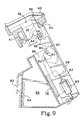
- Detents 59 and 60 displace pins 46 and 94 respectively, and thereby cause simultaneous rotation of preload and load doors 42 and 90, respectively, in opposite directions, as shown in Fig. 9. While both the preload and load doors 42 and 90, respectively, are open, ink sticks 12 are transferred, via gravity, from preload chamber(s) 32 to corresponding load chamber(s) 86.
- solenoid 63 is deactivated and ink transfer slide 58 is returned to its rest position.
- projecting pins 46 and 94 are released from detents 59 and 60, respectively, and the preload and load chamber doors, respectively, are returned to their closed, non-transfer positions illustrated in Fig. 10.
- Solid ink stick 12 is positioned in load chamber 86 and is therein melted to supply ink to the corresponding ink reservoir 82 during printing operations.
- the ink delivery system of the present invention thus utilizes a single, triggerable ink transfer system that simultaneously transfers solid ink sticks from one or more preload chambers to corresponding load chambers and ink reservoirs.
- the mechanical and logical simplicity of the system contributes to system reliability and acceptance and facilitates operator handling aspects of ink delivery.
- the integrated ink delivery system of the present invention is capable of providing a substantially continuous ink supply to print head ink reservoirs while reducing the risks of mechanical failure and operator mishandling.
- Fig. 11 illustrates the monitoring and control functions of a preferred embodiment of the ink delivery system of the present invention from a "READY" condition wherein at least one of the ink reservoirs is "HALF FULL” (i.e. , it can accept an ink stick), and none of the ink reservoirs is in an empty condition. Commands that appear on the operator interface module are shown in highlighted boxes.
- the ink delivery system is in a "READY” condition after an operator has inserted a solid ink stick into a preload chamber in response to an operator command or a "HALF FULL" ink level indication. Sensors detect when an ink stick has been positioned in a selected preload chamber, and print head carriage assembly 80 is moved to the home position aligned with preload assembly 30.
- the monitoring and control system confirms that the ink level in the appropriate ink reservoir is such that the ink reservoir can accept an ink stick. If the ink reservoir corresponding to the solid ink stick inserted in the preload chamber cannot accept an additional ink stick, a command appears on operator interface module 20 alerting the operator to remove the ink stick from the preload chamber. This situation indicates that an ink stick was inserted in the wrong preload chamber, and the system returns to the "READY" condition after the ink stick is removed.
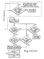
- Figs. 12(a) and (b), in combination, illustrate the monitoring and control functions of a preferred embodiment of the ink delivery system of the present invention from an "EMPTY" condition of at least one ink reservoir.
- an empty ink reservoir is capable of accepting two ink sticks, and two ink sticks may be introduced sequentially to the appropriate ink preload chamber.
- the system After the system has verified that the ink reservoir corresponding to the solid ink stick inserted in the preload chamber can accept additional ink, the system detects whether the ink level is below empty. If the ink level is not below empty, i.e. , the ink reservoir can accept one ink stick, the "PULL INK TRANSFER LEVER" command is given and the Standard Ink Transfer Functions are repeated. If the ink level is below empty, the "PULL INK TRANSFER LEVER" command is given and ink transfer functions proceed. After a first ink stick melt timer and a second ink stick load timer have been started, the operator interface module displays a "BUSY - MELTING INK" or "STOPPED - ADD INK" command.
- the system is returned to a "READY" condition and a second ink stick may be added, as described above. If the ink level does not exceed "EMPTY" after a predetermined time interval has elapsed, the control system indicates a system failure and printing operations cannot resume until the system failure has been corrected.
Landscapes
- Ink Jet (AREA)
- Impression-Transfer Materials And Handling Thereof (AREA)
- Particle Formation And Scattering Control In Inkjet Printers (AREA)
Applications Claiming Priority (2)
| Application Number | Priority Date | Filing Date | Title |
|---|---|---|---|
| US07/716,567 US5223860A (en) | 1991-06-17 | 1991-06-17 | Apparatus for supplying phase change ink to an ink jet printer |
| US716567 | 1991-06-17 |
Publications (3)
| Publication Number | Publication Date |
|---|---|
| EP0519700A2 true EP0519700A2 (de) | 1992-12-23 |
| EP0519700A3 EP0519700A3 (en) | 1993-09-22 |
| EP0519700B1 EP0519700B1 (de) | 1997-04-23 |
Family
ID=24878528
Family Applications (1)
| Application Number | Title | Priority Date | Filing Date |
|---|---|---|---|
| EP92305545A Expired - Lifetime EP0519700B1 (de) | 1991-06-17 | 1992-06-17 | Methode und Gerät zur Versorgung mit phasenwechselnder Tinte in einem Tintenstrahldrucker |
Country Status (4)
| Country | Link |
|---|---|
| US (2) | US5223860A (de) |
| EP (1) | EP0519700B1 (de) |
| JP (1) | JP2939681B2 (de) |
| DE (1) | DE69219212T2 (de) |
Cited By (9)
| Publication number | Priority date | Publication date | Assignee | Title |
|---|---|---|---|---|
| FR2737150A1 (fr) * | 1995-07-29 | 1997-01-31 | Seiko Epson Corp | Cartouche d'encre, et appareil, procede et ensemble d'affichage d'encre restante |
| EP0707969A3 (de) * | 1994-10-20 | 1997-08-20 | Canon Kk | Datenverarbeitungsgerät und Verfahren zur Verwendung in einem System mit entferntem Druckgerät |
| EP0820873A3 (de) * | 1996-07-24 | 1999-01-07 | Brother Kogyo Kabushiki Kaisha | Tintenversorgungsvorrichtung |
| EP0820872A3 (de) * | 1996-07-24 | 1999-01-20 | Brother Kogyo Kabushiki Kaisha | Tintentablette |
| EP0827835A3 (de) * | 1996-09-05 | 1999-09-01 | Tektronix, Inc. | Zuführsystem für feste Tintenstrahldrucktinte |
| EP1920935A1 (de) * | 2006-11-07 | 2008-05-14 | Xerox Corporation | Verschlüsselung zum Einsatz auf einer gemeinsamen Seite für Phasenwechsel-Tintenstifte |
| US7780283B2 (en) | 2006-11-07 | 2010-08-24 | Xerox Corporation | Independent keying and guidance for solid ink sticks |
| US7810918B2 (en) | 2006-11-07 | 2010-10-12 | Xerox Corporation | One way compatibility keying for solid ink sticks |
| CN102909962A (zh) * | 2007-12-21 | 2013-02-06 | 施乐公司 | 具有供应驱动器连接器的固体墨棒 |
Families Citing this family (174)
| Publication number | Priority date | Publication date | Assignee | Title |
|---|---|---|---|---|
| US5223860A (en) * | 1991-06-17 | 1993-06-29 | Tektronix, Inc. | Apparatus for supplying phase change ink to an ink jet printer |
| US5805191A (en) * | 1992-11-25 | 1998-09-08 | Tektronix, Inc. | Intermediate transfer surface application system |
| US5920332A (en) * | 1993-05-04 | 1999-07-06 | Markem Corporation | Ink barrier for fluid reservoir vacuum or pressure line |
| JP3264594B2 (ja) * | 1994-01-27 | 2002-03-11 | キヤノン株式会社 | 記録装置 |
| AU3186795A (en) * | 1994-09-16 | 1996-03-29 | Videojet Systems International, Inc. | Continuous ink jet printing system for use with hot-melt inks |
| US5510821B1 (en) * | 1994-09-20 | 2000-05-02 | Tektronix Inc | Solid ink stick |
| USD371802S (en) | 1995-01-20 | 1996-07-16 | Tektronix, Inc. | Solid ink stick for a color printer |
| USD380771S (en) * | 1995-01-20 | 1997-07-08 | Tektronix, Inc. | Solid ink stick for a color printer |
| USD371801S (en) | 1995-01-20 | 1996-07-16 | Tektronix, Inc. | Solid ink stick for color printer |
| USD383153S (en) * | 1995-01-20 | 1997-09-02 | Tektronix, Inc. | Solid ink stick for a color printer |
| USD372268S (en) | 1995-05-11 | 1996-07-30 | Tektronix, Inc. | Solid ink stick for a color printer |
| USD373139S (en) | 1995-05-11 | 1996-08-27 | Tektronix, Inc. | Solid ink stick for a color printer |
| USD372270S (en) | 1995-05-11 | 1996-07-30 | Tektronix, Inc. | Solid ink stick for a color printer |
| USD383154S (en) * | 1995-05-11 | 1997-09-02 | Tektronix, Inc. | Solid ink stick for a color printer |
| US5630510A (en) * | 1995-09-07 | 1997-05-20 | Polaroid Corporation | Packaging and loading solid ink nuggets for ink jet apparatus |
| GB9603582D0 (en) | 1996-02-20 | 1996-04-17 | Hewlett Packard Co | Method of accessing service resource items that are for use in a telecommunications system |
| US5861903A (en) * | 1996-03-07 | 1999-01-19 | Tektronix, Inc. | Ink feed system |
| US5734402A (en) * | 1996-03-07 | 1998-03-31 | Tekronix, Inc. | Solid ink stick feed system |
| US5784089A (en) * | 1996-03-07 | 1998-07-21 | Tektronix, Inc. | Melt plate design for a solid ink printer |
| USD379470S (en) * | 1996-04-18 | 1997-05-27 | Tektronix, Inc. | Solid ink stick for a color printer |
| USD379471S (en) * | 1996-04-18 | 1997-05-27 | Tektronix, Inc. | Solid ink stick for a color printer |
| USD379639S (en) * | 1996-04-18 | 1997-06-03 | Tektronix, Inc. | Solid ink stick for a color printer |
| USD379640S (en) * | 1996-04-18 | 1997-06-03 | Tektronix, Inc. | Solid ink stick for a color printer |
| USD392651S (en) | 1996-07-22 | 1998-03-24 | Brother Kogyo Kabushiki Kaisha | Solid ink |
| KR100209516B1 (ko) * | 1997-02-05 | 1999-07-15 | 윤종용 | 잉크젯 프린트 헤드의 잉크 저장 장치 및 방법 |
| USD407742S (en) | 1997-03-10 | 1999-04-06 | Tektronix, Inc. | Solid ink stick for a color printer |
| USD403699S (en) * | 1997-03-10 | 1999-01-05 | Tektronix, Inc. | Solid ink stick for a color printer |
| USD402308S (en) | 1997-03-10 | 1998-12-08 | Tektronix, Inc. | Solid ink stick for a color printer |
| USD416936S (en) * | 1997-03-10 | 1999-11-23 | Tektronix, Inc. | Solid ink stick for a color printer |
| USD409235S (en) * | 1997-03-10 | 1999-05-04 | Tektronix, Inc. | Solid ink stick for a color printer |
| USD403352S (en) | 1997-03-10 | 1998-12-29 | Tektronix, Inc. | Solid ink stick for a color printer |
| USD403351S (en) | 1997-03-10 | 1998-12-29 | Tektronix, Inc. | Solid ink stick for a color printer |
| USD410026S (en) | 1997-03-10 | 1999-05-18 | Tektronix, Inc. | Solid ink stick for a color printer |
| US6786420B1 (en) | 1997-07-15 | 2004-09-07 | Silverbrook Research Pty. Ltd. | Data distribution mechanism in the form of ink dots on cards |
| US5882724A (en) * | 1997-04-22 | 1999-03-16 | The Mead Corporation | Ink jet application of hot melt stilts to carbonless paper |
| US6089686A (en) * | 1997-05-28 | 2000-07-18 | Xerox Corporation | Method for supplying ink to an ink jet printer |
| US6170942B1 (en) * | 1997-07-04 | 2001-01-09 | Brother Kogyo Kabushiki Kaisha | Ink supply device |
| US6618117B2 (en) | 1997-07-12 | 2003-09-09 | Silverbrook Research Pty Ltd | Image sensing apparatus including a microcontroller |
| US7110024B1 (en) | 1997-07-15 | 2006-09-19 | Silverbrook Research Pty Ltd | Digital camera system having motion deblurring means |
| US20040119829A1 (en) | 1997-07-15 | 2004-06-24 | Silverbrook Research Pty Ltd | Printhead assembly for a print on demand digital camera system |
| US6690419B1 (en) | 1997-07-15 | 2004-02-10 | Silverbrook Research Pty Ltd | Utilising eye detection methods for image processing in a digital image camera |
| US6879341B1 (en) | 1997-07-15 | 2005-04-12 | Silverbrook Research Pty Ltd | Digital camera system containing a VLIW vector processor |
| US6624848B1 (en) | 1997-07-15 | 2003-09-23 | Silverbrook Research Pty Ltd | Cascading image modification using multiple digital cameras incorporating image processing |
| JPH1134354A (ja) * | 1997-07-18 | 1999-02-09 | Brother Ind Ltd | ホットメルトインクジェットプリンタ |
| US6183060B1 (en) | 1997-07-18 | 2001-02-06 | Brother Kogyo Kabushiki Kaisha | Ink jet recorder |
| US6045211A (en) * | 1997-07-18 | 2000-04-04 | Brother Kogyo Kabushiki Kaisha | Sensor and ink jet recorder including same |
| USD407743S (en) | 1998-01-06 | 1999-04-06 | Tektronix, Inc. | Solid ink stick for a color printer |
| USD413625S (en) | 1998-01-06 | 1999-09-07 | Tektronix, Inc. | Solid ink stick for a color printer |
| USD407110S (en) | 1998-01-06 | 1999-03-23 | Tektronix, Inc. | Solid ink stick for a color printer |
| USD408849S (en) | 1998-01-06 | 1999-04-27 | Tektronix, Inc. | Solid ink stick for a color printer |
| USD407109S (en) | 1998-01-06 | 1999-03-23 | Tektronix, Inc. | Solid ink stick for a color printer |
| USD407112S (en) | 1998-01-22 | 1999-03-23 | Textronix, Inc. | Solid ink stick for a color printer |
| USD407111S (en) | 1998-01-22 | 1999-03-23 | Tektronix, Inc. | Solid ink stick for a color printer |
| USD407745S (en) | 1998-01-22 | 1999-04-06 | Tektronix, Inc. | Solid ink stick for a color printer |
| USD410490S (en) * | 1998-05-05 | 1999-06-01 | Tektronix, Inc. | Solid ink stick for a color printer |
| USD412527S (en) * | 1998-05-05 | 1999-08-03 | Tektronix, Inc. | Solid ink stick for a color printer |
| USD409237S (en) * | 1998-05-05 | 1999-05-04 | Tektronix, Inc. | Solid ink stick for a color printer |
| USD412528S (en) * | 1998-05-05 | 1999-08-03 | Tektronix, Inc. | Solid ink stick for a color printer |
| USD414200S (en) | 1998-07-30 | 1999-09-21 | Tektronix, Inc. | Solid ink stick for a color printer |
| USD412934S (en) | 1998-07-31 | 1999-08-17 | Tektronix, Inc. | Solid ink stick for a color printer |
| USD415193S (en) * | 1998-07-31 | 1999-10-12 | Tektronix, Inc. | Solid ink stick for a color printer |
| AUPP702098A0 (en) | 1998-11-09 | 1998-12-03 | Silverbrook Research Pty Ltd | Image creation method and apparatus (ART73) |
| AUPP702198A0 (en) * | 1998-11-09 | 1998-12-03 | Silverbrook Research Pty Ltd | Image creation method and apparatus (ART79) |
| US7236271B2 (en) | 1998-11-09 | 2007-06-26 | Silverbrook Research Pty Ltd | Mobile telecommunication device with printhead and media drive |
| US7154580B2 (en) * | 1998-11-09 | 2006-12-26 | Silverbrook Research Pty Ltd | Image recordal and generation apparatus |
| AUPP701798A0 (en) * | 1998-11-09 | 1998-12-03 | Silverbrook Research Pty Ltd | Image creation method and apparatus (ART75) |
| AUPQ056099A0 (en) | 1999-05-25 | 1999-06-17 | Silverbrook Research Pty Ltd | A method and apparatus (pprint01) |
| USD436124S1 (en) | 1999-12-03 | 2001-01-09 | Xerox Corporation | Solid ink stick for a color printer |
| USD440249S1 (en) | 1999-12-03 | 2001-04-10 | Xerox Corporation | Solid ink stick for a color printer |
| USD436989S1 (en) | 1999-12-03 | 2001-01-30 | Xerox Corporation | Solid ink stick for a color printer |
| USD440248S1 (en) | 1999-12-03 | 2001-04-10 | Xerox Corporation | Solid ink stick for a color printer |
| US7171442B1 (en) * | 2000-09-18 | 2007-01-30 | Canon Kabushiki Kaisha | Printer maintenance scheme for a network centric printing system |
| USD453786S1 (en) | 2001-04-26 | 2002-02-19 | Xerox Corporation | Solid ink stick for solid ink printers |
| USD453787S1 (en) | 2001-04-26 | 2002-02-19 | Xerox Corporation | Solid ink stick for solid ink printers |
| US6840612B2 (en) * | 2002-04-29 | 2005-01-11 | Xerox Corporation | Guide for solid ink stick feed |
| US6857732B2 (en) * | 2002-04-29 | 2005-02-22 | Xerox Corporation | Visible identification of solid ink stick |
| US6761443B2 (en) | 2002-04-29 | 2004-07-13 | Xerox Corporation | Keying feature for solid ink stick |
| US6761444B2 (en) | 2002-04-29 | 2004-07-13 | Xerox Corporation | Channel keying for solid ink stick insertion |
| US6719419B2 (en) * | 2002-04-29 | 2004-04-13 | Xerox Corporation | Feed channel keying for solid ink stick feed |
| US6672716B2 (en) * | 2002-04-29 | 2004-01-06 | Xerox Corporation | Multiple portion solid ink stick |
| US6840613B2 (en) * | 2002-04-29 | 2005-01-11 | Xerox Corporation | Guide for solid ink stick feed |
| US6893121B2 (en) * | 2002-04-29 | 2005-05-17 | Xerox Corporaton | Solid ink stick set identification |
| US6722764B2 (en) | 2002-04-29 | 2004-04-20 | Xerox Corporation | Feed guidance and identification for ink stick |
| US6739713B2 (en) * | 2002-04-29 | 2004-05-25 | Xerox Corporation | Guide for solid ink stick feed |
| US6874880B2 (en) * | 2002-04-29 | 2005-04-05 | Xerox Corporation | Solid ink stick with identifiable shape |
| US6705710B2 (en) * | 2002-05-30 | 2004-03-16 | Xerox Corporation | Load and feed apparatus for solid ink |
| US6565201B1 (en) * | 2002-05-30 | 2003-05-20 | Xerox Corporation | Load and feed apparatus for solid ink |
| US6679591B2 (en) * | 2002-05-30 | 2004-01-20 | Xerox Corporation | Load and feed apparatus for solid ink |
| US6648435B1 (en) * | 2002-05-30 | 2003-11-18 | Xerox Corporation | Load and feed apparatus for solid ink |
| US6565200B1 (en) | 2002-05-30 | 2003-05-20 | Xerox Corporation | Load and feed apparatus for solid ink |
| US6709094B2 (en) * | 2002-05-30 | 2004-03-23 | Xerox Corporation | Load and feed apparatus for solid ink |
| EP1366910B1 (de) * | 2002-05-30 | 2006-06-21 | Xerox Corporation | Vorrichtung zum Laden und Zuführen für feste Tinte |
| US6561636B1 (en) * | 2002-05-30 | 2003-05-13 | Xerox Corporation | Load and feed apparatus for solid ink |
| US7104635B2 (en) * | 2002-05-30 | 2006-09-12 | Xerox Corporation | Load and feed apparatus for solid ink |
| USD482062S1 (en) | 2002-09-25 | 2003-11-11 | Xerox Corporation | Color ink stick for solid ink printer |
| USD478621S1 (en) | 2002-09-25 | 2003-08-19 | Xerox Corporation | Color ink stick for solid ink printer |
| USD483062S1 (en) | 2002-09-25 | 2003-12-02 | Xerox Corporation | Color ink stick for solid ink printer |
| USD481757S1 (en) | 2002-09-25 | 2003-11-04 | Xerox Corporation | Color ink stick for solid ink printer |
| USD481758S1 (en) | 2002-09-25 | 2003-11-04 | Xerox Corporation | Color ink stick for solid ink printer |
| USD479368S1 (en) | 2002-09-25 | 2003-09-02 | Xerox Corporation | Color ink stick for solid ink printer |
| USD482720S1 (en) | 2002-09-25 | 2003-11-25 | Xerox Corporation | Color ink stick for solid ink printer |
| USD482721S1 (en) | 2002-09-25 | 2003-11-25 | Xerox Corporation | Color ink stick for solid ink printer |
| USD482389S1 (en) | 2002-09-25 | 2003-11-18 | Xerox Corporation | Color ink stick for solid ink printer |
| USD483063S1 (en) | 2002-09-25 | 2003-12-02 | Xerox Corporation | Color ink stick for solid ink printer |
| USD478347S1 (en) | 2002-09-25 | 2003-08-12 | Xerox Corporation | Color ink stick for solid ink printer |
| USD481759S1 (en) | 2002-09-25 | 2003-11-04 | Xerox Corporation | Color ink stick for solid ink printer |
| USD500516S1 (en) | 2003-12-08 | 2005-01-04 | Xerox Corporation | Ink stick for phase change ink jet printer |
| USD506778S1 (en) | 2003-12-08 | 2005-06-28 | Xerox Corporation | Ink stick for phase change ink jet printer |
| USD506779S1 (en) | 2003-12-08 | 2005-06-28 | Xerox Corporation | Ink stick for phase change ink jet printer |
| USD500783S1 (en) | 2003-12-08 | 2005-01-11 | Xerox Corporation | Ink stick for phase change ink jet printer |
| USD544535S1 (en) | 2003-12-08 | 2007-06-12 | Xerox Corporation | Ink stick for phase change ink jet printer |
| USD500785S1 (en) | 2003-12-08 | 2005-01-11 | Xerox Corporation | Ink stick for phase change ink jet printer |
| USD505973S1 (en) | 2003-12-08 | 2005-06-07 | Xerox Corporation | Ink stick for phase change ink jet printer |
| USD500784S1 (en) | 2003-12-08 | 2005-01-11 | Xerox Corporation | Ink stick for phase change ink jet printer |
| USD500786S1 (en) | 2003-12-08 | 2005-01-11 | Xerox Corporation | Ink stick for phase change ink jet printer |
| USD505974S1 (en) | 2003-12-08 | 2005-06-07 | Xerox Corporation | Ink stick for phase change ink jet printer |
| JP2005186418A (ja) * | 2003-12-25 | 2005-07-14 | Dainippon Screen Mfg Co Ltd | 画像記録システム、画像記録装置、および印刷データ処理装置 |
| US7407276B2 (en) * | 2005-06-09 | 2008-08-05 | Xerox Corporation | Ink level sensing |
| US7425061B2 (en) * | 2005-06-09 | 2008-09-16 | Xerox Corporation | Ink consumption determination |
| US7591550B2 (en) * | 2005-06-09 | 2009-09-22 | Xerox Corporation | Ink consumption determination |
| US7458669B2 (en) * | 2005-06-09 | 2008-12-02 | Xerox Corporation | Ink consumption determination |
| US7503648B2 (en) * | 2005-06-09 | 2009-03-17 | Xerox Corporation | Ink consumption determination |
| KR20070087710A (ko) * | 2005-06-28 | 2007-08-29 | 삼성전자주식회사 | 고형 잉크젯 인쇄장치 |
| US7874661B2 (en) * | 2006-06-22 | 2011-01-25 | Xerox Corporation | Solid ink stick with coded markings and method and apparatus for reading markings |
| US7537326B2 (en) | 2006-06-23 | 2009-05-26 | Xerox Corporation | Solid ink stick with coded sensor feature |
| US7553008B2 (en) | 2006-06-23 | 2009-06-30 | Xerox Corporation | Ink loader for interfacing with solid ink sticks |
| US7517072B2 (en) | 2006-06-23 | 2009-04-14 | Xerox Corporation | Solid ink stick with enhanced differentiation |
| US7857439B2 (en) * | 2006-06-23 | 2010-12-28 | Xerox Corporation | Solid ink stick with interface element |
| US7648232B2 (en) * | 2006-07-12 | 2010-01-19 | Xerox Corporation | Solid ink stick with reliably encoded data |
| US7631963B2 (en) * | 2006-08-01 | 2009-12-15 | Xerox Corporation | Method of forming solid ink stick with coded mark |
| US7753509B2 (en) * | 2006-08-14 | 2010-07-13 | Xerox Corporation | Segmented ink stick |
| US7753510B2 (en) * | 2006-10-11 | 2010-07-13 | Xerox Corporation | Solid ink composition with post-melt mixing |
| US7682010B2 (en) * | 2006-10-11 | 2010-03-23 | Xerox Corporation | Solid ink stick with coating |
| US7690775B2 (en) * | 2006-11-07 | 2010-04-06 | Xerox Corporation | Solid ink sticks with corner guides |
| US7798624B2 (en) * | 2006-11-21 | 2010-09-21 | Xerox Corporation | Transport system for solid ink in a printer |
| US7976144B2 (en) * | 2006-11-21 | 2011-07-12 | Xerox Corporation | System and method for delivering solid ink sticks to a melting device through a non-linear guide |
| US7794072B2 (en) * | 2006-11-21 | 2010-09-14 | Xerox Corporation | Guide for printer solid ink transport and method |
| US7651210B2 (en) * | 2006-11-21 | 2010-01-26 | Xerox Corporation | Transport system for solid ink for cooperation with melt head in a printer |
| US7883195B2 (en) * | 2006-11-21 | 2011-02-08 | Xerox Corporation | Solid ink stick features for printer ink transport and method |
| US7726797B2 (en) * | 2006-11-28 | 2010-06-01 | Xerox Corporation | Intermediate side slot vertical ink constraint with offset support |
| US7753511B2 (en) * | 2006-11-28 | 2010-07-13 | Xerox Corporation | Lateral anti-skewing solution for solid ink |
| US7762655B2 (en) * | 2006-12-11 | 2010-07-27 | Xerox Corporation | Printer ink delivery system |
| US7878636B2 (en) * | 2006-12-12 | 2011-02-01 | Xerox Corporation | Solid ink stick chute for printer solid ink transport with mating solid ink stick chute |
| US7726798B2 (en) * | 2006-12-15 | 2010-06-01 | Xerox Corporation | Printer solid ink transport and method |
| US7722177B2 (en) * | 2006-12-22 | 2010-05-25 | Xerox Corporation | System for loading ink sticks configured for lateral anti-skewing |
| US7798626B2 (en) * | 2007-02-28 | 2010-09-21 | Xerox Corporation | System for loading and feeding solid ink sticks to an ink melter in a phase change ink printer |
| US7798627B2 (en) * | 2007-03-09 | 2010-09-21 | Xerox Corporation | Multi-position interlocking ink stick |
| US7878641B2 (en) * | 2007-03-09 | 2011-02-01 | Xerox Corporation | Solid ink stick with reversible keying and interlocking features |
| US7780284B2 (en) * | 2007-03-09 | 2010-08-24 | Xerox Corporation | Digital solid ink stick identification and recognition |
| US7819513B2 (en) * | 2007-03-09 | 2010-10-26 | Xerox Corporation | Solid ink stick with multiple axis interlocking |
| US7802880B2 (en) * | 2007-03-12 | 2010-09-28 | Xerox Corporation | Solid ink stick with canted surface |
| US7824027B2 (en) * | 2007-09-11 | 2010-11-02 | Xerox Corporation | Solid ink stick with anti jam edge bevel |
| US7909445B2 (en) * | 2007-09-11 | 2011-03-22 | Xerox Corporation | Solid ink stick delivery system with static constraints, strategic barriers and breakage controls |
| US7976118B2 (en) * | 2007-10-22 | 2011-07-12 | Xerox Corporation | Transport system for providing a continuous supply of solid ink to a melting assembly in a printer |
| US7891792B2 (en) * | 2007-11-06 | 2011-02-22 | Xerox Corporation | Solid ink stick with transition indicating region |
| US7891755B2 (en) * | 2007-12-18 | 2011-02-22 | Xerox Corporation | System and method for imaging ink supplies in a printer |
| US7883196B2 (en) * | 2007-12-21 | 2011-02-08 | Xerox Corporation | System for delivering solid ink through a feed channel having non-linear sections |
| US7887173B2 (en) * | 2008-01-18 | 2011-02-15 | Xerox Corporation | Transport system having multiple moving forces for solid ink delivery in a printer |
| US8272727B2 (en) * | 2008-02-14 | 2012-09-25 | Xerox Corporation | Mechanized feed channel barrier in a solid ink printer |
| US7883197B2 (en) * | 2008-02-27 | 2011-02-08 | Xerox Corporation | Transport system having single insertion port for solid ink delivery in a printer |
| US8118417B2 (en) * | 2008-03-06 | 2012-02-21 | Xerox Corporation | System and method for processing solid ink stick exception conditions in a solid ink printer |
| US8132877B2 (en) * | 2008-07-31 | 2012-03-13 | Xerox Corporation | User adaptable ink status conveyance system |
| US8052265B2 (en) * | 2008-09-22 | 2011-11-08 | Xerox Corporation | System and method for verifying position of an object before identifying the object |
| US8096647B2 (en) * | 2008-09-22 | 2012-01-17 | Xerox Corporation | Solid ink sticks having a verification interlock for verifying position of a solid ink stick before identifying the ink stick |
| US8083336B2 (en) * | 2009-01-19 | 2011-12-27 | Xerox Corporation | Ink stick jam detection and recovery system and method |
| US8136933B2 (en) * | 2009-01-30 | 2012-03-20 | Xerox Corporation | Solid ink melt tub with corrugated melt region and offset outlet |
| US8238538B2 (en) | 2009-05-28 | 2012-08-07 | Comcast Cable Communications, Llc | Stateful home phone service |
| US8240830B2 (en) * | 2010-03-10 | 2012-08-14 | Xerox Corporation | No spill, feed controlled removable container for delivering pelletized substances |
| US8382269B2 (en) * | 2010-04-13 | 2013-02-26 | Xerox Corporation | System and method that enables a solid ink printer to learn a solid ink stick type |
| US8240831B2 (en) | 2010-06-17 | 2012-08-14 | Xerox Corporation | System and method for controlling insertion of solid ink sticks into a printer |
| US8814336B2 (en) | 2011-12-22 | 2014-08-26 | Xerox Corporation | Solid ink stick configuration |
| US8876265B2 (en) | 2012-06-28 | 2014-11-04 | Xerox Corporation | Ink stick transport system |
| US8727478B2 (en) | 2012-10-17 | 2014-05-20 | Xerox Corporation | Ink loader having optical sensors to identify solid ink sticks |
| US8777386B2 (en) | 2012-10-17 | 2014-07-15 | Xerox Corporation | Solid ink stick having identical identifying features on a plurality of edges |
Family Cites Families (17)
| Publication number | Priority date | Publication date | Assignee | Title |
|---|---|---|---|---|
| US4490731A (en) * | 1982-11-22 | 1984-12-25 | Hewlett-Packard Company | Ink dispenser with "frozen" solid ink |
| US4609924A (en) * | 1984-10-15 | 1986-09-02 | Exxon Printing Systems, Inc. | Buffer reservoir for ink jet apparatus and method |
| US4593292A (en) * | 1984-10-15 | 1986-06-03 | Exxon Research And Engineering Co. | Ink jet apparatus and method of operating ink jet apparatus employing phase change ink melted as needed |
| CA1252669A (en) * | 1984-10-16 | 1989-04-18 | Arthur Mikalsen | Ink jet apparatus and method of operating the ink jet apparatus employing phase change ink |
| US4682185A (en) * | 1984-11-08 | 1987-07-21 | Martner John G | Ink jet method and apparatus utilizing a web of hot melt ink |
| US4682187A (en) * | 1984-11-08 | 1987-07-21 | Martner John G | Ink jet method and apparatus utilizing grandular or hot melt ink |
| US4714936A (en) * | 1985-06-24 | 1987-12-22 | Howtek, Inc. | Ink jet printer |
| US4739339A (en) * | 1986-02-14 | 1988-04-19 | Dataproducts Corporation | Cartridge and method of using a cartridge for phase change ink in an ink jet apparatus |
| US4823146A (en) * | 1986-02-14 | 1989-04-18 | Dataproducts Corporation | Cartridge and method of using a cartridge for phase change ink in an ink jet apparatus |
| US4814786A (en) * | 1987-04-28 | 1989-03-21 | Spectra, Inc. | Hot melt ink supply system |
| JPS6425135U (de) * | 1987-08-05 | 1989-02-10 | ||
| US4864330A (en) * | 1987-09-09 | 1989-09-05 | Spectra, Inc. | Method of forming a hot melt ink unit |
| US5172135A (en) * | 1987-09-09 | 1992-12-15 | Spectra, Inc. | Hot melt ink supply unit |
| DE3850562T2 (de) * | 1987-09-09 | 1995-02-09 | Spectra Inc | Heissschmelzende tintenzufuhreinheit. |
| US4870430A (en) * | 1987-11-02 | 1989-09-26 | Howtek, Inc. | Solid ink delivery system |
| US5038157A (en) * | 1989-08-18 | 1991-08-06 | Apple Computer, Inc. | Apparatus and method for loading solid ink pellets into a printer |
| US5223860A (en) * | 1991-06-17 | 1993-06-29 | Tektronix, Inc. | Apparatus for supplying phase change ink to an ink jet printer |
-
1991
- 1991-06-17 US US07/716,567 patent/US5223860A/en not_active Expired - Lifetime
-
1992
- 1992-06-17 DE DE69219212T patent/DE69219212T2/de not_active Expired - Lifetime
- 1992-06-17 JP JP4183004A patent/JP2939681B2/ja not_active Expired - Fee Related
- 1992-06-17 EP EP92305545A patent/EP0519700B1/de not_active Expired - Lifetime
-
1993
- 1993-06-23 US US08/082,209 patent/US5442387A/en not_active Expired - Lifetime
Cited By (14)
| Publication number | Priority date | Publication date | Assignee | Title |
|---|---|---|---|---|
| EP0707969A3 (de) * | 1994-10-20 | 1997-08-20 | Canon Kk | Datenverarbeitungsgerät und Verfahren zur Verwendung in einem System mit entferntem Druckgerät |
| US6771378B2 (en) | 1994-10-20 | 2004-08-03 | Canon Kabushiki Kaisha | Information processing apparatus which obtains information concerning residual ink amount from an attached ink jet printer |
| US6223131B1 (en) | 1995-07-29 | 2001-04-24 | Seiko Epson Corporation | Ink cartridge for an ink-jet recording apparatus, and a system for detecting and displaying an ink consumption state of an ink cartridge |
| FR2737150A1 (fr) * | 1995-07-29 | 1997-01-31 | Seiko Epson Corp | Cartouche d'encre, et appareil, procede et ensemble d'affichage d'encre restante |
| EP0820872A3 (de) * | 1996-07-24 | 1999-01-20 | Brother Kogyo Kabushiki Kaisha | Tintentablette |
| US6053608A (en) * | 1996-07-24 | 2000-04-25 | Brother Kogyo Kabushiki Kaisha | Ink pellet with step configuration including slidable bearing surfaces |
| EP0820873A3 (de) * | 1996-07-24 | 1999-01-07 | Brother Kogyo Kabushiki Kaisha | Tintenversorgungsvorrichtung |
| EP0827835A3 (de) * | 1996-09-05 | 1999-09-01 | Tektronix, Inc. | Zuführsystem für feste Tintenstrahldrucktinte |
| EP1920935A1 (de) * | 2006-11-07 | 2008-05-14 | Xerox Corporation | Verschlüsselung zum Einsatz auf einer gemeinsamen Seite für Phasenwechsel-Tintenstifte |
| US7780283B2 (en) | 2006-11-07 | 2010-08-24 | Xerox Corporation | Independent keying and guidance for solid ink sticks |
| US7810918B2 (en) | 2006-11-07 | 2010-10-12 | Xerox Corporation | One way compatibility keying for solid ink sticks |
| US7854501B2 (en) | 2006-11-07 | 2010-12-21 | Xerox Corporation | Common side insertion keying for phase change ink sticks |
| CN102909962A (zh) * | 2007-12-21 | 2013-02-06 | 施乐公司 | 具有供应驱动器连接器的固体墨棒 |
| CN102909962B (zh) * | 2007-12-21 | 2015-03-11 | 施乐公司 | 具有供应驱动器连接器的固体墨棒 |
Also Published As
| Publication number | Publication date |
|---|---|
| JP2939681B2 (ja) | 1999-08-25 |
| US5442387A (en) | 1995-08-15 |
| EP0519700A3 (en) | 1993-09-22 |
| US5223860A (en) | 1993-06-29 |
| DE69219212D1 (de) | 1997-05-28 |
| DE69219212T2 (de) | 1997-09-18 |
| JPH05193152A (ja) | 1993-08-03 |
| EP0519700B1 (de) | 1997-04-23 |
Similar Documents
| Publication | Publication Date | Title |
|---|---|---|
| EP0519700B1 (de) | Methode und Gerät zur Versorgung mit phasenwechselnder Tinte in einem Tintenstrahldrucker | |
| US4870430A (en) | Solid ink delivery system | |
| JP3189752B2 (ja) | 固体インク供給装置及び方法並びに装填方法 | |
| EP0610965B1 (de) | Tintenstrahlaufzeichnungsgerät und Tintenkassette dafür | |
| US6179401B1 (en) | Multi-component installation feedback system for replacement print cartridges, valve holders, and service station cassettes for on board ink delivery systems replenishment | |
| EP2310207B1 (de) | Behälterinstallationsführung für eine fluidejektoranordnung | |
| US4814786A (en) | Hot melt ink supply system | |
| US7845750B2 (en) | Ink jet type recording apparatus, ink type information setting method in the apparatus and ink cartridge used in the apparatus | |
| ES2252453T3 (es) | Metodo y aparato para proporcionar caracteristicas de extraccion de un tintero a un sistema de impresion. | |
| JP2003312019A (ja) | ソリッドインク棒供給のための供給チャンネルキーイング | |
| US7192110B2 (en) | Inkjet cartridge detection and switching apparatus | |
| JP2003312020A (ja) | ソリッドインク棒挿入のためのチャンネルキーイング | |
| CA2048034C (en) | Ink jet recording apparatus | |
| KR20030011698A (ko) | 프린터 구성품의 프린터와의 호환성을 설정하기 위한메커니즘 및 잉크젯 프린터 | |
| EP2465685B1 (de) | Flüssigkeitszufuhrvorrichtung | |
| US6460982B1 (en) | Ink supplement system | |
| US6170942B1 (en) | Ink supply device | |
| JP2002029041A (ja) | インクジェットプリンタ | |
| JPH05155012A (ja) | ホットメルトインクジェット記録方法 | |
| US7128409B2 (en) | Replaceable printing consumable with features facilitating intuitive installation by a user | |
| KR20030011700A (ko) | 탈착식 프린터 구성품의 정확한 설치 메커니즘 및 잉크젯프린터 | |
| JPH10211718A (ja) | インクジェットプリント装置 | |
| JP2010173245A (ja) | インクカートリッジの装着方法 | |
| JP2003001844A (ja) | インク供給装置、インク供給方法、および記録装置 | |
| US8118417B2 (en) | System and method for processing solid ink stick exception conditions in a solid ink printer |
Legal Events
| Date | Code | Title | Description |
|---|---|---|---|
| PUAI | Public reference made under article 153(3) epc to a published international application that has entered the european phase |
Free format text: ORIGINAL CODE: 0009012 |
|
| AK | Designated contracting states |
Kind code of ref document: A2 Designated state(s): DE FR GB IT |
|
| PUAL | Search report despatched |
Free format text: ORIGINAL CODE: 0009013 |
|
| AK | Designated contracting states |
Kind code of ref document: A3 Designated state(s): DE FR GB IT |
|
| 17P | Request for examination filed |
Effective date: 19931119 |
|
| 17Q | First examination report despatched |
Effective date: 19950315 |
|
| GRAG | Despatch of communication of intention to grant |
Free format text: ORIGINAL CODE: EPIDOS AGRA |
|
| GRAH | Despatch of communication of intention to grant a patent |
Free format text: ORIGINAL CODE: EPIDOS IGRA |
|
| GRAH | Despatch of communication of intention to grant a patent |
Free format text: ORIGINAL CODE: EPIDOS IGRA |
|
| GRAA | (expected) grant |
Free format text: ORIGINAL CODE: 0009210 |
|
| AK | Designated contracting states |
Kind code of ref document: B1 Designated state(s): DE FR GB IT |
|
| PG25 | Lapsed in a contracting state [announced via postgrant information from national office to epo] |
Ref country code: IT Free format text: LAPSE BECAUSE OF FAILURE TO SUBMIT A TRANSLATION OF THE DESCRIPTION OR TO PAY THE FEE WITHIN THE PRESCRIBED TIME-LIMIT;WARNING: LAPSES OF ITALIAN PATENTS WITH EFFECTIVE DATE BEFORE 2007 MAY HAVE OCCURRED AT ANY TIME BEFORE 2007. THE CORRECT EFFECTIVE DATE MAY BE DIFFERENT FROM THE ONE RECORDED. Effective date: 19970423 |
|
| REF | Corresponds to: |
Ref document number: 69219212 Country of ref document: DE Date of ref document: 19970528 |
|
| ET | Fr: translation filed | ||
| PLBE | No opposition filed within time limit |
Free format text: ORIGINAL CODE: 0009261 |
|
| STAA | Information on the status of an ep patent application or granted ep patent |
Free format text: STATUS: NO OPPOSITION FILED WITHIN TIME LIMIT |
|
| 26N | No opposition filed | ||
| REG | Reference to a national code |
Ref country code: GB Ref legal event code: 732E |
|
| REG | Reference to a national code |
Ref country code: FR Ref legal event code: TP |
|
| REG | Reference to a national code |
Ref country code: GB Ref legal event code: IF02 |
|
| PGFP | Annual fee paid to national office [announced via postgrant information from national office to epo] |
Ref country code: FR Payment date: 20110621 Year of fee payment: 20 |
|
| PGFP | Annual fee paid to national office [announced via postgrant information from national office to epo] |
Ref country code: GB Payment date: 20110615 Year of fee payment: 20 |
|
| PGFP | Annual fee paid to national office [announced via postgrant information from national office to epo] |
Ref country code: DE Payment date: 20110615 Year of fee payment: 20 |
|
| REG | Reference to a national code |
Ref country code: DE Ref legal event code: R071 Ref document number: 69219212 Country of ref document: DE |
|
| REG | Reference to a national code |
Ref country code: DE Ref legal event code: R071 Ref document number: 69219212 Country of ref document: DE |
|
| REG | Reference to a national code |
Ref country code: GB Ref legal event code: PE20 Expiry date: 20120616 |
|
| PG25 | Lapsed in a contracting state [announced via postgrant information from national office to epo] |
Ref country code: DE Free format text: LAPSE BECAUSE OF EXPIRATION OF PROTECTION Effective date: 20120619 |
|
| PG25 | Lapsed in a contracting state [announced via postgrant information from national office to epo] |
Ref country code: GB Free format text: LAPSE BECAUSE OF EXPIRATION OF PROTECTION Effective date: 20120616 |