EP0519768A2 - Aufzeichnungsträger mit hoher Speicherdichte und Verfahren zum Auslesen eines solchen Trägers - Google Patents
Aufzeichnungsträger mit hoher Speicherdichte und Verfahren zum Auslesen eines solchen Trägers Download PDFInfo
- Publication number
- EP0519768A2 EP0519768A2 EP92401336A EP92401336A EP0519768A2 EP 0519768 A2 EP0519768 A2 EP 0519768A2 EP 92401336 A EP92401336 A EP 92401336A EP 92401336 A EP92401336 A EP 92401336A EP 0519768 A2 EP0519768 A2 EP 0519768A2
- Authority
- EP
- European Patent Office
- Prior art keywords
- information
- reading
- laser beam
- power density
- wavelength
- Prior art date
- Legal status (The legal status is an assumption and is not a legal conclusion. Google has not performed a legal analysis and makes no representation as to the accuracy of the status listed.)
- Granted
Links
- 238000000034 method Methods 0.000 title claims abstract description 27
- 239000000463 material Substances 0.000 claims abstract description 98
- 230000003287 optical effect Effects 0.000 claims abstract description 28
- 239000011347 resin Substances 0.000 claims description 9
- 229920005989 resin Polymers 0.000 claims description 9
- 239000000758 substrate Substances 0.000 claims description 7
- 239000004065 semiconductor Substances 0.000 claims description 5
- 229920000642 polymer Polymers 0.000 claims description 4
- 239000013078 crystal Substances 0.000 claims description 3
- 239000011521 glass Substances 0.000 claims description 3
- PYWVYCXTNDRMGF-UHFFFAOYSA-N rhodamine B Chemical compound [Cl-].C=12C=CC(=[N+](CC)CC)C=C2OC2=CC(N(CC)CC)=CC=C2C=1C1=CC=CC=C1C(O)=O PYWVYCXTNDRMGF-UHFFFAOYSA-N 0.000 claims description 3
- JBRZTFJDHDCESZ-UHFFFAOYSA-N AsGa Chemical compound [As]#[Ga] JBRZTFJDHDCESZ-UHFFFAOYSA-N 0.000 claims description 2
- 229910001218 Gallium arsenide Inorganic materials 0.000 claims description 2
- 238000001514 detection method Methods 0.000 claims description 2
- 229920003229 poly(methyl methacrylate) Polymers 0.000 claims description 2
- 239000004926 polymethyl methacrylate Substances 0.000 claims description 2
- 229910052761 rare earth metal Inorganic materials 0.000 claims description 2
- 150000002910 rare earth metals Chemical class 0.000 claims description 2
- 230000035945 sensitivity Effects 0.000 claims 1
- 230000004044 response Effects 0.000 description 6
- 230000005415 magnetization Effects 0.000 description 5
- 230000005291 magnetic effect Effects 0.000 description 4
- 230000008569 process Effects 0.000 description 4
- 230000006399 behavior Effects 0.000 description 3
- 238000005286 illumination Methods 0.000 description 3
- 229910052751 metal Inorganic materials 0.000 description 3
- 230000005855 radiation Effects 0.000 description 3
- XKRFYHLGVUSROY-UHFFFAOYSA-N Argon Chemical compound [Ar] XKRFYHLGVUSROY-UHFFFAOYSA-N 0.000 description 2
- PXHVJJICTQNCMI-UHFFFAOYSA-N Nickel Chemical compound [Ni] PXHVJJICTQNCMI-UHFFFAOYSA-N 0.000 description 2
- 239000000969 carrier Substances 0.000 description 2
- 238000005119 centrifugation Methods 0.000 description 2
- 238000012822 chemical development Methods 0.000 description 2
- 238000010438 heat treatment Methods 0.000 description 2
- 239000002184 metal Substances 0.000 description 2
- 229920006254 polymer film Polymers 0.000 description 2
- 210000001747 pupil Anatomy 0.000 description 2
- 239000000243 solution Substances 0.000 description 2
- 230000009466 transformation Effects 0.000 description 2
- VYZAMTAEIAYCRO-UHFFFAOYSA-N Chromium Chemical compound [Cr] VYZAMTAEIAYCRO-UHFFFAOYSA-N 0.000 description 1
- 206010019345 Heat stroke Diseases 0.000 description 1
- 229910052779 Neodymium Inorganic materials 0.000 description 1
- OAICVXFJPJFONN-UHFFFAOYSA-N Phosphorus Chemical compound [P] OAICVXFJPJFONN-UHFFFAOYSA-N 0.000 description 1
- 208000007180 Sunstroke Diseases 0.000 description 1
- 241001080024 Telles Species 0.000 description 1
- 238000010521 absorption reaction Methods 0.000 description 1
- 230000009471 action Effects 0.000 description 1
- 229910052786 argon Inorganic materials 0.000 description 1
- 230000005540 biological transmission Effects 0.000 description 1
- KYAZRUPZRJALEP-UHFFFAOYSA-N bismuth manganese Chemical compound [Mn].[Bi] KYAZRUPZRJALEP-UHFFFAOYSA-N 0.000 description 1
- 238000006243 chemical reaction Methods 0.000 description 1
- 229910052804 chromium Inorganic materials 0.000 description 1
- 239000011651 chromium Substances 0.000 description 1
- 229910017052 cobalt Inorganic materials 0.000 description 1
- 239000010941 cobalt Substances 0.000 description 1
- GUTLYIVDDKVIGB-UHFFFAOYSA-N cobalt atom Chemical compound [Co] GUTLYIVDDKVIGB-UHFFFAOYSA-N 0.000 description 1
- 230000001427 coherent effect Effects 0.000 description 1
- 230000007423 decrease Effects 0.000 description 1
- 238000005137 deposition process Methods 0.000 description 1
- 238000010586 diagram Methods 0.000 description 1
- 238000005516 engineering process Methods 0.000 description 1
- ZAMACTJOCIFTPJ-UHFFFAOYSA-N ethyl dibunate Chemical compound CC(C)(C)C1=CC=C2C(S(=O)(=O)OCC)=CC(C(C)(C)C)=CC2=C1 ZAMACTJOCIFTPJ-UHFFFAOYSA-N 0.000 description 1
- 229950001503 ethyl dibunate Drugs 0.000 description 1
- 238000002347 injection Methods 0.000 description 1
- 239000007924 injection Substances 0.000 description 1
- 230000001678 irradiating effect Effects 0.000 description 1
- 230000002045 lasting effect Effects 0.000 description 1
- 239000000696 magnetic material Substances 0.000 description 1
- 239000007769 metal material Substances 0.000 description 1
- 125000002496 methyl group Chemical group [H]C([H])([H])* 0.000 description 1
- 230000004048 modification Effects 0.000 description 1
- 238000012986 modification Methods 0.000 description 1
- QEFYFXOXNSNQGX-UHFFFAOYSA-N neodymium atom Chemical compound [Nd] QEFYFXOXNSNQGX-UHFFFAOYSA-N 0.000 description 1
- 229910052759 nickel Inorganic materials 0.000 description 1
- 239000011368 organic material Substances 0.000 description 1
- 230000005298 paramagnetic effect Effects 0.000 description 1
- 229910052698 phosphorus Inorganic materials 0.000 description 1
- 239000011574 phosphorus Substances 0.000 description 1
- 239000007787 solid Substances 0.000 description 1
- 230000003595 spectral effect Effects 0.000 description 1
- 230000007704 transition Effects 0.000 description 1
Images



Classifications
-
- G—PHYSICS
- G11—INFORMATION STORAGE
- G11B—INFORMATION STORAGE BASED ON RELATIVE MOVEMENT BETWEEN RECORD CARRIER AND TRANSDUCER
- G11B7/00—Recording or reproducing by optical means, e.g. recording using a thermal beam of optical radiation by modifying optical properties or the physical structure, reproducing using an optical beam at lower power by sensing optical properties; Record carriers therefor
- G11B7/24—Record carriers characterised by shape, structure or physical properties, or by the selection of the material
- G11B7/241—Record carriers characterised by shape, structure or physical properties, or by the selection of the material characterised by the selection of the material
- G11B7/242—Record carriers characterised by shape, structure or physical properties, or by the selection of the material characterised by the selection of the material of recording layers
- G11B7/244—Record carriers characterised by shape, structure or physical properties, or by the selection of the material characterised by the selection of the material of recording layers comprising organic materials only
- G11B7/245—Record carriers characterised by shape, structure or physical properties, or by the selection of the material characterised by the selection of the material of recording layers comprising organic materials only containing a polymeric component
-
- G—PHYSICS
- G11—INFORMATION STORAGE
- G11B—INFORMATION STORAGE BASED ON RELATIVE MOVEMENT BETWEEN RECORD CARRIER AND TRANSDUCER
- G11B11/00—Recording on or reproducing from the same record carrier wherein for these two operations the methods are covered by different main groups of groups G11B3/00 - G11B7/00 or by different subgroups of group G11B9/00; Record carriers therefor
- G11B11/10—Recording on or reproducing from the same record carrier wherein for these two operations the methods are covered by different main groups of groups G11B3/00 - G11B7/00 or by different subgroups of group G11B9/00; Record carriers therefor using recording by magnetic means or other means for magnetisation or demagnetisation of a record carrier, e.g. light induced spin magnetisation; Demagnetisation by thermal or stress means in the presence or not of an orienting magnetic field
- G11B11/105—Recording on or reproducing from the same record carrier wherein for these two operations the methods are covered by different main groups of groups G11B3/00 - G11B7/00 or by different subgroups of group G11B9/00; Record carriers therefor using recording by magnetic means or other means for magnetisation or demagnetisation of a record carrier, e.g. light induced spin magnetisation; Demagnetisation by thermal or stress means in the presence or not of an orienting magnetic field using a beam of light or a magnetic field for recording by change of magnetisation and a beam of light for reproducing, i.e. magneto-optical, e.g. light-induced thermomagnetic recording, spin magnetisation recording, Kerr or Faraday effect reproducing
- G11B11/10502—Recording on or reproducing from the same record carrier wherein for these two operations the methods are covered by different main groups of groups G11B3/00 - G11B7/00 or by different subgroups of group G11B9/00; Record carriers therefor using recording by magnetic means or other means for magnetisation or demagnetisation of a record carrier, e.g. light induced spin magnetisation; Demagnetisation by thermal or stress means in the presence or not of an orienting magnetic field using a beam of light or a magnetic field for recording by change of magnetisation and a beam of light for reproducing, i.e. magneto-optical, e.g. light-induced thermomagnetic recording, spin magnetisation recording, Kerr or Faraday effect reproducing characterised by the transducing operation to be executed
- G11B11/10504—Recording
- G11B11/10506—Recording by modulating only the light beam of the transducer
-
- G—PHYSICS
- G11—INFORMATION STORAGE
- G11B—INFORMATION STORAGE BASED ON RELATIVE MOVEMENT BETWEEN RECORD CARRIER AND TRANSDUCER
- G11B11/00—Recording on or reproducing from the same record carrier wherein for these two operations the methods are covered by different main groups of groups G11B3/00 - G11B7/00 or by different subgroups of group G11B9/00; Record carriers therefor
- G11B11/10—Recording on or reproducing from the same record carrier wherein for these two operations the methods are covered by different main groups of groups G11B3/00 - G11B7/00 or by different subgroups of group G11B9/00; Record carriers therefor using recording by magnetic means or other means for magnetisation or demagnetisation of a record carrier, e.g. light induced spin magnetisation; Demagnetisation by thermal or stress means in the presence or not of an orienting magnetic field
- G11B11/105—Recording on or reproducing from the same record carrier wherein for these two operations the methods are covered by different main groups of groups G11B3/00 - G11B7/00 or by different subgroups of group G11B9/00; Record carriers therefor using recording by magnetic means or other means for magnetisation or demagnetisation of a record carrier, e.g. light induced spin magnetisation; Demagnetisation by thermal or stress means in the presence or not of an orienting magnetic field using a beam of light or a magnetic field for recording by change of magnetisation and a beam of light for reproducing, i.e. magneto-optical, e.g. light-induced thermomagnetic recording, spin magnetisation recording, Kerr or Faraday effect reproducing
- G11B11/10502—Recording on or reproducing from the same record carrier wherein for these two operations the methods are covered by different main groups of groups G11B3/00 - G11B7/00 or by different subgroups of group G11B9/00; Record carriers therefor using recording by magnetic means or other means for magnetisation or demagnetisation of a record carrier, e.g. light induced spin magnetisation; Demagnetisation by thermal or stress means in the presence or not of an orienting magnetic field using a beam of light or a magnetic field for recording by change of magnetisation and a beam of light for reproducing, i.e. magneto-optical, e.g. light-induced thermomagnetic recording, spin magnetisation recording, Kerr or Faraday effect reproducing characterised by the transducing operation to be executed
- G11B11/10515—Reproducing
-
- G—PHYSICS
- G11—INFORMATION STORAGE
- G11B—INFORMATION STORAGE BASED ON RELATIVE MOVEMENT BETWEEN RECORD CARRIER AND TRANSDUCER
- G11B11/00—Recording on or reproducing from the same record carrier wherein for these two operations the methods are covered by different main groups of groups G11B3/00 - G11B7/00 or by different subgroups of group G11B9/00; Record carriers therefor
- G11B11/10—Recording on or reproducing from the same record carrier wherein for these two operations the methods are covered by different main groups of groups G11B3/00 - G11B7/00 or by different subgroups of group G11B9/00; Record carriers therefor using recording by magnetic means or other means for magnetisation or demagnetisation of a record carrier, e.g. light induced spin magnetisation; Demagnetisation by thermal or stress means in the presence or not of an orienting magnetic field
- G11B11/105—Recording on or reproducing from the same record carrier wherein for these two operations the methods are covered by different main groups of groups G11B3/00 - G11B7/00 or by different subgroups of group G11B9/00; Record carriers therefor using recording by magnetic means or other means for magnetisation or demagnetisation of a record carrier, e.g. light induced spin magnetisation; Demagnetisation by thermal or stress means in the presence or not of an orienting magnetic field using a beam of light or a magnetic field for recording by change of magnetisation and a beam of light for reproducing, i.e. magneto-optical, e.g. light-induced thermomagnetic recording, spin magnetisation recording, Kerr or Faraday effect reproducing
- G11B11/10582—Record carriers characterised by the selection of the material or by the structure or form
- G11B11/10586—Record carriers characterised by the selection of the material or by the structure or form characterised by the selection of the material
-
- G—PHYSICS
- G11—INFORMATION STORAGE
- G11B—INFORMATION STORAGE BASED ON RELATIVE MOVEMENT BETWEEN RECORD CARRIER AND TRANSDUCER
- G11B7/00—Recording or reproducing by optical means, e.g. recording using a thermal beam of optical radiation by modifying optical properties or the physical structure, reproducing using an optical beam at lower power by sensing optical properties; Record carriers therefor
- G11B7/004—Recording, reproducing or erasing methods; Read, write or erase circuits therefor
- G11B7/0045—Recording
- G11B7/00455—Recording involving reflectivity, absorption or colour changes
-
- G—PHYSICS
- G11—INFORMATION STORAGE
- G11B—INFORMATION STORAGE BASED ON RELATIVE MOVEMENT BETWEEN RECORD CARRIER AND TRANSDUCER
- G11B7/00—Recording or reproducing by optical means, e.g. recording using a thermal beam of optical radiation by modifying optical properties or the physical structure, reproducing using an optical beam at lower power by sensing optical properties; Record carriers therefor
- G11B7/004—Recording, reproducing or erasing methods; Read, write or erase circuits therefor
- G11B7/005—Reproducing
-
- G—PHYSICS
- G11—INFORMATION STORAGE
- G11B—INFORMATION STORAGE BASED ON RELATIVE MOVEMENT BETWEEN RECORD CARRIER AND TRANSDUCER
- G11B7/00—Recording or reproducing by optical means, e.g. recording using a thermal beam of optical radiation by modifying optical properties or the physical structure, reproducing using an optical beam at lower power by sensing optical properties; Record carriers therefor
- G11B7/24—Record carriers characterised by shape, structure or physical properties, or by the selection of the material
-
- G—PHYSICS
- G11—INFORMATION STORAGE
- G11B—INFORMATION STORAGE BASED ON RELATIVE MOVEMENT BETWEEN RECORD CARRIER AND TRANSDUCER
- G11B7/00—Recording or reproducing by optical means, e.g. recording using a thermal beam of optical radiation by modifying optical properties or the physical structure, reproducing using an optical beam at lower power by sensing optical properties; Record carriers therefor
- G11B7/24—Record carriers characterised by shape, structure or physical properties, or by the selection of the material
- G11B7/241—Record carriers characterised by shape, structure or physical properties, or by the selection of the material characterised by the selection of the material
- G11B7/242—Record carriers characterised by shape, structure or physical properties, or by the selection of the material characterised by the selection of the material of recording layers
- G11B7/243—Record carriers characterised by shape, structure or physical properties, or by the selection of the material characterised by the selection of the material of recording layers comprising inorganic materials only, e.g. ablative layers
-
- G—PHYSICS
- G11—INFORMATION STORAGE
- G11B—INFORMATION STORAGE BASED ON RELATIVE MOVEMENT BETWEEN RECORD CARRIER AND TRANSDUCER
- G11B7/00—Recording or reproducing by optical means, e.g. recording using a thermal beam of optical radiation by modifying optical properties or the physical structure, reproducing using an optical beam at lower power by sensing optical properties; Record carriers therefor
- G11B7/24—Record carriers characterised by shape, structure or physical properties, or by the selection of the material
- G11B7/241—Record carriers characterised by shape, structure or physical properties, or by the selection of the material characterised by the selection of the material
- G11B7/252—Record carriers characterised by shape, structure or physical properties, or by the selection of the material characterised by the selection of the material of layers other than recording layers
-
- G—PHYSICS
- G11—INFORMATION STORAGE
- G11B—INFORMATION STORAGE BASED ON RELATIVE MOVEMENT BETWEEN RECORD CARRIER AND TRANSDUCER
- G11B7/00—Recording or reproducing by optical means, e.g. recording using a thermal beam of optical radiation by modifying optical properties or the physical structure, reproducing using an optical beam at lower power by sensing optical properties; Record carriers therefor
- G11B7/24—Record carriers characterised by shape, structure or physical properties, or by the selection of the material
- G11B7/241—Record carriers characterised by shape, structure or physical properties, or by the selection of the material characterised by the selection of the material
- G11B7/242—Record carriers characterised by shape, structure or physical properties, or by the selection of the material characterised by the selection of the material of recording layers
- G11B7/243—Record carriers characterised by shape, structure or physical properties, or by the selection of the material characterised by the selection of the material of recording layers comprising inorganic materials only, e.g. ablative layers
- G11B2007/24302—Metals or metalloids
- G11B2007/2431—Metals or metalloids group 13 elements (B, Al, Ga, In)
-
- G—PHYSICS
- G11—INFORMATION STORAGE
- G11B—INFORMATION STORAGE BASED ON RELATIVE MOVEMENT BETWEEN RECORD CARRIER AND TRANSDUCER
- G11B7/00—Recording or reproducing by optical means, e.g. recording using a thermal beam of optical radiation by modifying optical properties or the physical structure, reproducing using an optical beam at lower power by sensing optical properties; Record carriers therefor
- G11B7/24—Record carriers characterised by shape, structure or physical properties, or by the selection of the material
- G11B7/241—Record carriers characterised by shape, structure or physical properties, or by the selection of the material characterised by the selection of the material
- G11B7/242—Record carriers characterised by shape, structure or physical properties, or by the selection of the material characterised by the selection of the material of recording layers
- G11B7/243—Record carriers characterised by shape, structure or physical properties, or by the selection of the material characterised by the selection of the material of recording layers comprising inorganic materials only, e.g. ablative layers
- G11B2007/24302—Metals or metalloids
- G11B2007/24314—Metals or metalloids group 15 elements (e.g. Sb, Bi)
Definitions
- the present invention relates to the storage of information by optical means as well as the reading of this information.
- the maximum storable density is limited by diffraction at the wavelength of writing or reading.
- this density limit may be situated, for example, around the bit per square micrometer.
- the present invention proposes a new optical writing method capable of generating information media with high density of surface storage.
- the present invention also provides a method for reading an information medium with high density of surface storage.
- the laser beam having a Gaussian distribution
- the illumination in the pupil of the objective is a truncated Gaussian.
- it has a certain spectral width.
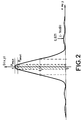
- the distribution of illumination at the focal point of the objective is not exactly a function of Airy, but the approximation made here is sufficient to be considered as representative of the real phenomenon.
- the base of the Airy spot has a radius greater than R om .
- the radius R om rather corresponds to the spot size at mid height of the curve D (x, y) and makes it possible to define the extent of information entered with a sufficient power density.
- the present invention proposes using an optically strongly non-linear material (Ma) and a focused laser beam having a maximum power density Pmax such that the threshold power density Pseuil of the material (Ma) is slightly less than Pmax.
- FIG. 2 shows that the invention exploits the upper part of the curve D (x, y). It is interested in regions in which a small variation in the writing power density results in significant decreases in the area of the written information.
- the optical response of the material (Ma) must be as strongly non-linear as possible and the power densities Pmax and Pseuil are tuned so as to be on either side of the inflection point of the curve illustrating the optical response of the material (Ma) with the power density it receives.
- This curve is shown diagrammatically in FIG. 3.
- the hatched part of FIG. 2 corresponds to zones in which the material has optically transformed and which define the regions in which information has been recorded.
- the size of the information can thus be greatly reduced compared to the prior art and therefore with an equivalent storage area, the storage density is notably increased.
- the power of the laser is chosen so that the power density in the laser beam only exceeds the threshold power density of the material in a surface area several times smaller than the surface of the spot.
- beam focus (for example at least three times smaller).
- the material (Ma) can be a photosensitive resin or a magnetooptical material or a metallic material or a phase transition material.
- the present invention also relates to the information carrier recorded by the writing method described above, the information carrier being characterized in that if L is the wavelength of the writing beam, the elements inscribed have at least one lateral dimension less than L / 2, these elements of information possibly being holes.
- the material (Ma) can be deposited on a material (Mb) capable of generating light radiation itself by stimulated emission.
- the wavelengths used neither make it possible to write information of very small dimensions (less than L if L is the writing wavelength), or even to read information of very small dimensions which would have been registered by other methods, for reasons of focusing of the reading beam and of crosstalk.
- Information detection is done by detecting the presence or absence of a stimulated broadcast.
- the material (Ma) used can be metallic, the regions (Ra) can be holes and the material (Mb) can be as well a semiconductor as a polymer doped with a dye or a glass or a doped crystal with rare earths.
- the present invention finally relates to the optical storage medium capable of being read by the reading method according to the invention, this medium comprising at least 2 layers of material deposited on a substrate, the upper layer serving as medium for the recording of information, the lower layer representing a medium capable of emitting light by stimulated emission during reading.
- the present invention provides a new method of optical writing on a support comprising a layer of material (Ma) whose optical response is highly non-linear; the material (Ma) can be a photosensitive resin whose chemical development makes it possible to reach a submicron resolution.
- the response of certain photosensitive resins may also be highly nonlinear as shown in FIG. 4. It is a Shipley S1400 resin revealed with an MF 314 developer, To being the initial thickness, T being the thickness after sunstroke.
- the curve shown in Figure 4 shows the evolution of the% T / To ratio as a function of the energy density received by the resin.
- the behavior of this material is particularly interesting for defining a power density of the focused writing laser beam close to the threshold power density of the photosensitive resin used.
- the material (Ma) can be a material in which a variation in the refractive index can be photoinduced.
- One of the advantages of such materials is that they can record information in optical form without going through a phase of chemical development. It may for example be a photopolymer.
- Photosensitive resins or photopolymers can be easily deposited on any substrate by the centrifugation method.
- the thickness of the material layer (Ma) is easily adjustable by determining the speed of centrifugation and by that of the concentration of the initial solution of material (Ma).
- the material (Ma) can also be a magnetooptical material. Under the action of a laser beam, the magnetooptical material heats up, the local temperature rise causes variations in the magnetic parameter and the information bit is defined by the zone in which the previously oriented magnetization takes a direction antiparallel. More precisely, the layer of material (Ma) can be brought to saturation beforehand by application of an external magnetic field greater than the coercive field at ambient (the coercive field Hc corresponds to the field capable of canceling the induced magnetization and is illustrated by the hysteresis cycle of figure 5 giving the evolution of the magnetization J with the magnetic field H). Then one applies in the plane of the layer an external field lower than the coercive field of direction opposite to that of the field of saturation.
- the magnetization switches in an antiparallel direction, thus defining a bit.
- the transformation of the magnetooptical material therefore takes place only when the power density that it receives is greater than a certain threshold power density corresponding to a heating of the material such that the latter is brought to a temperature greater than the Curie temperature. Tc.
- the layers of magnetooptical materials can be produced from cobalt combined with chromium or nickel or even phosphorus.
- the material manganese-bismuth also exhibits the hexagonal system in which it crystallizes interesting magnetic properties.
- Table I illustrates exemplary embodiments of support made of magnetooptical material, the deposition process of which depends on the nature of the material.
- the recording of information can be done with a short wavelength laser (for example a blue argon laser emitting at 457.9 nm) or a coherent source obtained by frequency doubling of a semiconductor laser or a solid laser of the YAG neodymium type focused on the surface of the material layer (Ma).
- a short wavelength laser for example a blue argon laser emitting at 457.9 nm
- a coherent source obtained by frequency doubling of a semiconductor laser or a solid laser of the YAG neodymium type focused on the surface of the material layer (Ma).
- the registration process according to the invention can be carried out on media in the form of discs, cards (credit card type) or even tapes.
- FIG. 6 illustrates an example of a device allowing the recording of information on a flat support disc which can be rotated about an axis.
- the focused laser beam For recording composed of a laser beam (F) focused via a focusing objective (OF) on the layer of material (Ma) deposited on a substrate (S).
- the focused laser beam generates a focusing spot (T) of which only a central part (C) creates a transformation of the material (Ma) corresponding to the information entered,
- the transformed zone (ZT) is of lateral dimensions several times smaller than those of the spot (T). This assumes that the power density at the center of the spot is little more than the power density of the reaction threshold of the material, for example at most 20% higher.
- the focusing optics can be moved radially relative to the disc (in a conventional manner) so that the entire useful surface of the disc can be scanned by the recording laser beam.
- the modulation of the recording beam according to the signal to be written on the medium can be obtained in several ways.
- a light modulator Pockels cells or other
- This modulator MO
- the laser itself can be modulated (semiconductor laser in particular by modulation of the injection current).
- the information can be of binary type, each entry by the useful part of the focused laser beam representing a bit of information or the information can be of analog type and in this case the useful information is represented by the length d 'an area modified by the laser beam or the distance separating two successive local modifications of the material layer (Ma).
- Synchronization is provided between the modulation command and the relative movement of the disc and the focusing task so that the information is written with a well-defined spatial distribution.
- Such an areal density of information makes it possible to envisage optical recording in the field of high definition television.
- a program for one hour of television corresponds to approximately 1012 bits, or an area of 400 to 500 cm2.
- the reading of information of very small dimensions very close together imperatively requires to use sources of short wavelengths (for example blue source) in order to avoid as much as possible the simultaneous reading of several information due to the width of the spot. focusing the reading beam.
- sources of short wavelengths for example blue source
- the present invention also makes maximum use of the non-linearity of certain materials for reading information so that only the central part of the focusing spot of the reading beam can read information of dimensions smaller than the focusing spot.
- the reading method according to the invention it becomes possible with the reading method according to the invention to read with a reading beam emitting at L information of dimensions clearly smaller than L.
- the wavelength of the read beam can even be greater than the wavelength of the write beam.
- the invention proposes to couple the layer of material containing the information to a layer of material capable of be the seat of stimulated emission.
- a material (Ma) in which the information previously entered is transparent to the reading length L1 of the reading beam, which by irradiating the material (Mb) only very locally generates an emission stimulated at the wavelength L2 where the power density of the beam at L1 is greater than the threshold power density beyond which there is stimulated emission.
- the material (Mb) can be of varied nature, it can be a polymer doped with rhodamine for example, indeed the threshold power density of such a material is of the order of 100 kW / cm2 .
- a laser emitting at the wavelength L1 a few mW can focus on a spot of light of 0.5 ⁇ m in size and is capable of causing a stimulated emission making it possible to reveal the information stored in the material (Ma).
- the material (Mb) can also be a semi-conductor of the gallium arsenide type emitting in the near infrared.
- the material Mb can also consist of a glass or a crystal doped with a rare earth (Neodyne in particular) and capable of emitting radiation in the near infrared.
- a rare earth Neodyne in particular
- the choice of reading laser is dictated by the nature of the material Mb chosen. Its wavelength must be located in the absorption bands of the material Mb so as to induce the emission of the material Mb, at a different wavelength, generally greater than that of the reading laser.
- the reading method is thus very different from the optical media reading methods known to those skilled in the art, in that the reading is not obtained by diffraction of the reading beam by the information elements, but by light emission from the media itself at a wavelength different from that of the reading beam.
- Reading can also be carried out with a frequency doubling material emitting at L1 / 2.
- organic materials of the polymer type exist which have good non-linear optical properties at frequency doubling and whose implementation and cost are particularly advantageous.
- FIG. 7 illustrates an example of a device using an information medium according to the invention.
- This support consists of a layer of metal and the information stored is holes in this layer.
- This layer is superimposed on a polymer film (Mb) of polymethylmethacrylate methyl type doped with rhodamine, this film of material (Mb) being itself deposited on a transparent substrate.
- the reading process is carried out in transmission, a laser beam is focused using an objective (OF) on the polymer film, the metallic elements not engraved at the writing serve as a mask for the incident reading beam emitting at the wavelength L1.
- OF objective
- the power density received in a region Rb is such that only the regions R′b of the regions Rb receive a power density sufficient to generate a stimulated emission at the wavelength L2.
- the regions of the material (Ma) different from the regions Ra although receiving the incident reading beam transmit only a focused power density lower than the threshold power density of the material (Mb) and cannot therefore generate a stimulated emission at the level of this material. This reading process makes it possible to discriminate information and neighboring information even if these are very small (less than 0.2 ⁇ m) and separated by a very small distance (less than 0.2 ⁇ m).
- a filter can be placed at the outlet of the substrate, allowing only the emission wavelength L2 to pass.
- the filtered signal can be collected by a photodiode so as to restore the stored signal.
Landscapes
- Chemical & Material Sciences (AREA)
- Inorganic Chemistry (AREA)
- Optical Recording Or Reproduction (AREA)
- Optical Record Carriers And Manufacture Thereof (AREA)
Applications Claiming Priority (2)
| Application Number | Priority Date | Filing Date | Title |
|---|---|---|---|
| FR9106111A FR2676853B1 (fr) | 1991-05-21 | 1991-05-21 | Procede d'ecriture et de lecture optique sur support d'informations a stockage haute densite. |
| FR9106111 | 1991-05-21 |
Publications (3)
| Publication Number | Publication Date |
|---|---|
| EP0519768A2 true EP0519768A2 (de) | 1992-12-23 |
| EP0519768A3 EP0519768A3 (en) | 1993-01-13 |
| EP0519768B1 EP0519768B1 (de) | 1997-06-18 |
Family
ID=9412957
Family Applications (1)
| Application Number | Title | Priority Date | Filing Date |
|---|---|---|---|
| EP92401336A Expired - Lifetime EP0519768B1 (de) | 1991-05-21 | 1992-05-15 | Aufzeichnungsträger mit hoher Speicherdichte und Verfahren zum Auslesen eines solchen Trägers |
Country Status (5)
| Country | Link |
|---|---|
| US (1) | US5323372A (de) |
| EP (1) | EP0519768B1 (de) |
| JP (1) | JP3781782B2 (de) |
| DE (1) | DE69220417T2 (de) |
| FR (1) | FR2676853B1 (de) |
Cited By (7)
| Publication number | Priority date | Publication date | Assignee | Title |
|---|---|---|---|---|
| US5400949A (en) * | 1991-09-19 | 1995-03-28 | Nokia Mobile Phones Ltd. | Circuit board assembly |
| EP0606129A3 (de) * | 1993-01-07 | 1996-10-02 | Sharp Kk | Vorrichtung zur magnetooptischen Aufzeichnung und Wiedergabe. |
| WO2001084545A3 (en) * | 2000-04-28 | 2002-02-28 | Dataplay Inc | Miniature optical disk for data storage |
| US6619100B2 (en) | 2000-12-21 | 2003-09-16 | Dphi Acquisitions, Inc. | Crimping tool for metal hub plate |
| US6738333B1 (en) | 2000-05-30 | 2004-05-18 | Dphi Acquisitions, Inc. | Format for recording data in a storage disk |
| US6912189B2 (en) | 2000-05-30 | 2005-06-28 | Dphi Acquisitions, Inc. | Skip list management for a write-once optical disk |
| US6990058B1 (en) | 2000-04-03 | 2006-01-24 | Dphi Acquisitions, Inc. | Structure and method for storing data on optical disks |
Families Citing this family (15)
| Publication number | Priority date | Publication date | Assignee | Title |
|---|---|---|---|---|
| US5835469A (en) * | 1990-05-25 | 1998-11-10 | Hitachi, Ltd. | High-density information recording/reproducing method |
| WO1995026548A1 (en) * | 1994-03-25 | 1995-10-05 | Hitachi, Ltd. | High density information recording and reproducing method |
| JPH08509566A (ja) * | 1993-12-23 | 1996-10-08 | トムソン−セーエスエフ | 記録媒体の上で情報を書き込み/読み出す光システムおよびその方法 |
| FR2722319B1 (fr) * | 1994-07-08 | 1996-08-14 | Thomson Csf | Dispositif de visualisation couleurs |
| FR2732783B1 (fr) * | 1995-04-07 | 1997-05-16 | Thomson Csf | Dispositif compact de retroprojection |
| FR2742911B1 (fr) * | 1995-12-21 | 1998-02-06 | Thomson Csf | Support d'enregistrement/lecture optique d'informations et procede d'enregistrement |
| FR2751398B1 (fr) * | 1996-07-16 | 1998-08-28 | Thomson Csf | Dispositif d'eclairage et application a l'eclairage d'un ecran transmissif |
| FR2755516B1 (fr) | 1996-11-05 | 1999-01-22 | Thomson Csf | Dispositif compact d'illumination |
| FR2755530B1 (fr) * | 1996-11-05 | 1999-01-22 | Thomson Csf | Dispositif de visualisation et ecran plat de television utilisant ce dispositif |
| FR2784185B1 (fr) | 1998-10-06 | 2001-02-02 | Thomson Csf | Dispositif pour l'harmonisation entre une voie d'emission laser et une voie passive d'observation |
| US6028835A (en) * | 1998-11-03 | 2000-02-22 | Thomas; Michael E. | Integrated read/write head for ferroelectric optical storage |
| US6483801B1 (en) * | 2000-07-31 | 2002-11-19 | Terastor Corporation | Optical storage devices without mass transfer and spots |
| FR2819061B1 (fr) * | 2000-12-28 | 2003-04-11 | Thomson Csf | Dispositif de controle de polarisation dans une liaison optique |
| KR100415048B1 (ko) * | 2001-06-29 | 2004-01-13 | 한국과학기술연구원 | 고밀도 광 정보저장 매체 |
| US20050191059A1 (en) * | 2004-01-12 | 2005-09-01 | Clariphy | Use of low-speed components in high-speed optical fiber transceivers |
Family Cites Families (6)
| Publication number | Priority date | Publication date | Assignee | Title |
|---|---|---|---|---|
| US3812496A (en) * | 1972-08-22 | 1974-05-21 | Trw Inc | Optical signal recording system |
| US4360908A (en) * | 1980-02-25 | 1982-11-23 | Eastman Kodak Company | Physically optimized optical disc structure, method and apparatus |
| JPS5954051A (ja) * | 1982-09-20 | 1984-03-28 | Pioneer Electronic Corp | 光学式情報記録担体及びその製造方法 |
| NL8801327A (nl) * | 1988-05-24 | 1989-12-18 | Philips Nv | Methode voor het optisch aftasten van een informatievlak en optische registratiedragers en aftastinrichtingen geschikt voor toepassing van de methode. |
| JP2904434B2 (ja) * | 1988-08-12 | 1999-06-14 | パイオニア株式会社 | 光学式情報記録媒体及びその再生装置 |
| JPH02308439A (ja) * | 1989-05-22 | 1990-12-21 | Toshiba Corp | 光記録媒体及びその再生方法 |
-
1991
- 1991-05-21 FR FR9106111A patent/FR2676853B1/fr not_active Expired - Lifetime
-
1992
- 1992-05-15 DE DE69220417T patent/DE69220417T2/de not_active Expired - Lifetime
- 1992-05-15 EP EP92401336A patent/EP0519768B1/de not_active Expired - Lifetime
- 1992-05-20 JP JP12752992A patent/JP3781782B2/ja not_active Expired - Lifetime
- 1992-05-21 US US07/886,169 patent/US5323372A/en not_active Expired - Lifetime
Cited By (8)
| Publication number | Priority date | Publication date | Assignee | Title |
|---|---|---|---|---|
| US5400949A (en) * | 1991-09-19 | 1995-03-28 | Nokia Mobile Phones Ltd. | Circuit board assembly |
| EP0606129A3 (de) * | 1993-01-07 | 1996-10-02 | Sharp Kk | Vorrichtung zur magnetooptischen Aufzeichnung und Wiedergabe. |
| US6990058B1 (en) | 2000-04-03 | 2006-01-24 | Dphi Acquisitions, Inc. | Structure and method for storing data on optical disks |
| WO2001084545A3 (en) * | 2000-04-28 | 2002-02-28 | Dataplay Inc | Miniature optical disk for data storage |
| US6817026B2 (en) | 2000-04-28 | 2004-11-09 | Dphi Acquisitions, Inc. | Magnetic hub assembly for data storage disk |
| US6738333B1 (en) | 2000-05-30 | 2004-05-18 | Dphi Acquisitions, Inc. | Format for recording data in a storage disk |
| US6912189B2 (en) | 2000-05-30 | 2005-06-28 | Dphi Acquisitions, Inc. | Skip list management for a write-once optical disk |
| US6619100B2 (en) | 2000-12-21 | 2003-09-16 | Dphi Acquisitions, Inc. | Crimping tool for metal hub plate |
Also Published As
| Publication number | Publication date |
|---|---|
| EP0519768B1 (de) | 1997-06-18 |
| FR2676853B1 (fr) | 1993-12-03 |
| JP3781782B2 (ja) | 2006-05-31 |
| DE69220417T2 (de) | 1997-10-16 |
| EP0519768A3 (en) | 1993-01-13 |
| US5323372A (en) | 1994-06-21 |
| JPH06215439A (ja) | 1994-08-05 |
| DE69220417D1 (de) | 1997-07-24 |
| FR2676853A1 (fr) | 1992-11-27 |
Similar Documents
| Publication | Publication Date | Title |
|---|---|---|
| EP0519768B1 (de) | Aufzeichnungsträger mit hoher Speicherdichte und Verfahren zum Auslesen eines solchen Trägers | |
| KR0163023B1 (ko) | 정보 면 광학 주사 방법 및 장치와 이 주사 방법에 의해 주사되는 광학 기록 캐리어 | |
| EP0455539B1 (de) | System für optische Aufnahme von Daten auf Scheiben und entsprechende Verfahren zum Lesen und Schreiben | |
| Watanabe et al. | New optical recording material for video disc system | |
| Bartolini et al. | Optical disk systems emerge | |
| US20020048225A1 (en) | Recording medium, recording and reproducing method and recording and reproducing apparatus | |
| FR2676302A1 (fr) | Procede de lecture des informations contenues dans un disque optique. | |
| EP0686298B1 (de) | Verfahren und optisches system zur aufzeichnung/wiedergabe von information auf einem aufzeichnungsmedium | |
| EP0700038B1 (de) | Optisches Wiedergabe-/Aufzeichnungssystem für ein Aufzeichnungsmedium und Anwendung für eine Aufzeichnungsscheibe | |
| EP0022682B1 (de) | Optischer Lesekopf mit Halbleiter-Laserquelle und eine mit optischer Reflexion arbeitende Lesevorrichtung zum Lesen eines Informationsträgers, die einen solchen optischen Lesekopf enthält | |
| FR2734660A1 (fr) | Memoire de masse de type optique, a couche photosensible d'enregistrement de donnees | |
| US8018815B2 (en) | Micro-Fresnel zone plate optical devices using densely accumulated ray points | |
| EP0889466B1 (de) | Optisches Aufzeichnungsmedium mit zwei übereinander angeordneten Schichten, Aufzeichnungsgerät und Leseverfahren dafür | |
| EP0461956B1 (de) | Optischer Informationsspeicher aus überlagerten Schichten | |
| FR2521760A1 (fr) | Procede thermo-optique d'inscription d'information sur support et dispositif mettant en oeuvre ce procede | |
| FR2710443A1 (fr) | Procédé d'enregistrement d'informations sur un disque optique et de lecture de celles-ci, support d'enregistrement et agencement de lecture pour la mise en Óoeuvre du procédé. | |
| Redmond et al. | Holographic data storage in a DX-center material | |
| FR2504301A1 (fr) | Support d'informations mobile et dispositif d'enregistrement-lecture comprenant un tel support | |
| Spitz et al. | Early experiments on optical disc storage | |
| FR2714511A1 (fr) | Procédé et système optiques d'inscription/lecture d'informations sur un support d'enregistrement. | |
| FR2722605A1 (fr) | Procede et systeme optiques d'inscription/lecture d'informations sur un support d'enregistrement | |
| FR2855901A1 (fr) | Lecteur/enregistreur de disque optique multipiste | |
| JP2000122513A (ja) | 光記録媒体、光記録方法、光記録装置、光再生方法および光再生装置 | |
| McColgan et al. | Phase-change disk optical correlator |
Legal Events
| Date | Code | Title | Description |
|---|---|---|---|
| PUAI | Public reference made under article 153(3) epc to a published international application that has entered the european phase |
Free format text: ORIGINAL CODE: 0009012 |
|
| PUAL | Search report despatched |
Free format text: ORIGINAL CODE: 0009013 |
|
| AK | Designated contracting states |
Kind code of ref document: A2 Designated state(s): DE GB NL |
|
| AK | Designated contracting states |
Kind code of ref document: A3 Designated state(s): DE GB NL |
|
| 17P | Request for examination filed |
Effective date: 19930324 |
|
| RAP1 | Party data changed (applicant data changed or rights of an application transferred) |
Owner name: THOMSON-CSF |
|
| 17Q | First examination report despatched |
Effective date: 19950726 |
|
| GRAG | Despatch of communication of intention to grant |
Free format text: ORIGINAL CODE: EPIDOS AGRA |
|
| GRAH | Despatch of communication of intention to grant a patent |
Free format text: ORIGINAL CODE: EPIDOS IGRA |
|
| GRAH | Despatch of communication of intention to grant a patent |
Free format text: ORIGINAL CODE: EPIDOS IGRA |
|
| GRAA | (expected) grant |
Free format text: ORIGINAL CODE: 0009210 |
|
| AK | Designated contracting states |
Kind code of ref document: B1 Designated state(s): DE GB NL |
|
| REF | Corresponds to: |
Ref document number: 69220417 Country of ref document: DE Date of ref document: 19970724 |
|
| GBT | Gb: translation of ep patent filed (gb section 77(6)(a)/1977) |
Effective date: 19970717 |
|
| PLBE | No opposition filed within time limit |
Free format text: ORIGINAL CODE: 0009261 |
|
| STAA | Information on the status of an ep patent application or granted ep patent |
Free format text: STATUS: NO OPPOSITION FILED WITHIN TIME LIMIT |
|
| 26N | No opposition filed | ||
| REG | Reference to a national code |
Ref country code: GB Ref legal event code: IF02 |
|
| NLT1 | Nl: modifications of names registered in virtue of documents presented to the patent office pursuant to art. 16 a, paragraph 1 |
Owner name: THALES |
|
| PGFP | Annual fee paid to national office [announced via postgrant information from national office to epo] |
Ref country code: NL Payment date: 20090504 Year of fee payment: 18 |
|
| REG | Reference to a national code |
Ref country code: GB Ref legal event code: 732E Free format text: REGISTERED BETWEEN 20090813 AND 20090819 |
|
| REG | Reference to a national code |
Ref country code: NL Ref legal event code: V1 Effective date: 20101201 |
|
| PG25 | Lapsed in a contracting state [announced via postgrant information from national office to epo] |
Ref country code: NL Free format text: LAPSE BECAUSE OF NON-PAYMENT OF DUE FEES Effective date: 20101201 |
|
| PGFP | Annual fee paid to national office [announced via postgrant information from national office to epo] |
Ref country code: GB Payment date: 20110421 Year of fee payment: 20 |
|
| PGFP | Annual fee paid to national office [announced via postgrant information from national office to epo] |
Ref country code: DE Payment date: 20110531 Year of fee payment: 20 |
|
| REG | Reference to a national code |
Ref country code: DE Ref legal event code: R071 Ref document number: 69220417 Country of ref document: DE |
|
| REG | Reference to a national code |
Ref country code: GB Ref legal event code: PE20 Expiry date: 20120514 |
|
| PG25 | Lapsed in a contracting state [announced via postgrant information from national office to epo] |
Ref country code: GB Free format text: LAPSE BECAUSE OF EXPIRATION OF PROTECTION Effective date: 20120514 |
|
| PG25 | Lapsed in a contracting state [announced via postgrant information from national office to epo] |
Ref country code: DE Free format text: LAPSE BECAUSE OF EXPIRATION OF PROTECTION Effective date: 20120516 |