EP0519773A1 - Procédé et dispositif de recalage continu d'images en veille panoramique - Google Patents
Procédé et dispositif de recalage continu d'images en veille panoramique Download PDFInfo
- Publication number
- EP0519773A1 EP0519773A1 EP92401384A EP92401384A EP0519773A1 EP 0519773 A1 EP0519773 A1 EP 0519773A1 EP 92401384 A EP92401384 A EP 92401384A EP 92401384 A EP92401384 A EP 92401384A EP 0519773 A1 EP0519773 A1 EP 0519773A1
- Authority
- EP
- European Patent Office
- Prior art keywords
- image
- characteristic points
- deformation
- parameters
- panoramic
- Prior art date
- Legal status (The legal status is an assumption and is not a legal conclusion. Google has not performed a legal analysis and makes no representation as to the accuracy of the status listed.)
- Granted
Links
Images


Classifications
-
- G—PHYSICS
- G01—MEASURING; TESTING
- G01S—RADIO DIRECTION-FINDING; RADIO NAVIGATION; DETERMINING DISTANCE OR VELOCITY BY USE OF RADIO WAVES; LOCATING OR PRESENCE-DETECTING BY USE OF THE REFLECTION OR RERADIATION OF RADIO WAVES; ANALOGOUS ARRANGEMENTS USING OTHER WAVES
- G01S3/00—Direction-finders for determining the direction from which infrasonic, sonic, ultrasonic or electromagnetic waves, or particle emission, not having a directional significance, are being received
- G01S3/78—Direction-finders for determining the direction from which infrasonic, sonic, ultrasonic or electromagnetic waves, or particle emission, not having a directional significance, are being received using electromagnetic waves other than radio waves
- G01S3/782—Systems for determining direction or deviation from predetermined direction
- G01S3/785—Systems for determining direction or deviation from predetermined direction using adjustment of orientation of directivity characteristics of a detector or detector system to give a desired condition of signal derived from that detector or detector system
- G01S3/786—Systems for determining direction or deviation from predetermined direction using adjustment of orientation of directivity characteristics of a detector or detector system to give a desired condition of signal derived from that detector or detector system the desired condition being maintained automatically
- G01S3/7864—T.V. type tracking systems
- G01S3/7865—T.V. type tracking systems using correlation of the live video image with a stored image
-
- G—PHYSICS
- G01—MEASURING; TESTING
- G01S—RADIO DIRECTION-FINDING; RADIO NAVIGATION; DETERMINING DISTANCE OR VELOCITY BY USE OF RADIO WAVES; LOCATING OR PRESENCE-DETECTING BY USE OF THE REFLECTION OR RERADIATION OF RADIO WAVES; ANALOGOUS ARRANGEMENTS USING OTHER WAVES
- G01S17/00—Systems using the reflection or reradiation of electromagnetic waves other than radio waves, e.g. lidar systems
- G01S17/88—Lidar systems specially adapted for specific applications
- G01S17/89—Lidar systems specially adapted for specific applications for mapping or imaging
Definitions
- the present invention relates to a method and a device for continuous image registration in panoramic standby. It applies in particular to panoramic imaging systems for surveillance.
- the image can belong to the range of visible or infrared wavelengths.
- the invention relates to the fields of image processing, optronics and signal processing. It can for example be applied to the registration of the data obtained by a panoramic surveillance radar.
- Panoramic imaging systems allow monitoring at an angle of 360 °. They consist of a rotating optical head and a linear detector. At all times, the linear detector forms a column of the panoramic image.
- the panoramic image is obtained by the juxtaposition of the columns of images formed by this linear sensor in rotation around a vertical axis. The number of columns per turn can reach several tens of thousands.
- Image registration consists in matching the successive images obtained during the successive turns of the sensor.
- the registration of images is for example necessary in the case of movement detection or tracking of moving objects. Indeed, to detect revealing movements of targets or potential threats, it is necessary to analyze the difference between the current image and the image formed in the previous turn.
- this problem is complicated by the own movements or oscillations of the standby device, namely the rotating optical head and the linear detector, inherent in certain applications. This is particularly the case when this device is installed on a mobile carrier or on top of a mast for example.
- the problem to be resolved therefore consists in developing a method making it possible to accurately estimate the distortions of the images obtained by the rotating watch device in order to make possible the detection of moving objects by difference between the present image and the previous image corrected for its deformation.
- Known solutions use global registration techniques, such as that described by the article "Recursive motion estimation based on a model of the camera dynamics" published in the journal Signal Processing V: Theoric and Applications (L. Torres, E. Margrau and MA Lagunnas editor).
- Other solutions are applicable when each image is obtained almost instantaneously, on television type imagery for example, and the deformation can be reduced to a global parametric transformation such as a translation-rotation in two dimensions or in three dimensions. using scene depth models.
- Non-parametric techniques based on the search for elastic transformations using a hypothesis of continuity of the deformation are sometimes applicable. Nevertheless, defects appear with these solutions, in particular an imprecision in the mapping of the images and a heaviness of the calculations.
- the object of the invention is to overcome the aforementioned drawbacks.
- the subject of the invention is a process for continuous registration of images in panoramic standby using characteristic points extracted from the current image and characteristic points predicted from the previous image, characterized in that it consists in using a Kalman filter to estimate the instantaneous parameters of image deformation from measurements of the differences between the predicted characteristic points and those obtained in the current image.
- the invention also relates to a device for implementing the above method.
- the main advantages of the invention are that it allows image registration compatible with surveillance applications, in particular the detection and characterization of the movements of objects in panoramic standby while reducing the complexity of the resolution calculations.
- the method according to the invention comprises five steps.
- This process uses the particular structure of panoramic images which is continuous and closed, that is to say that there is neither right edge nor left edge. It also uses the a priori knowledge that one can have on the movements of the watch device, knowledge of a statistical nature easily representable by a Gaussian-Markovian model.
- the method consists in a step 1 of extracting the characteristic points from the panoramic image, in a step 2 of managing the list of characteristic points, in a step 3 of predicting the instantaneous parameters of the deformation a priori according to the technique of the filter Kalman, following a step 4 to match the characteristic points which have just been extracted from the current image with the list of the characteristic points predicted from those of the previous image and the deformation parameters estimated a priori during step 3, finally following a step 5 to estimate the instantaneous parameters of the deformation from measurements of the differences between the predicted characteristic points and those obtained in the current image, by means of a Kalman filter.
- This last step constitutes the registration of images.
- Kalman filtering technique used in the process is well known to those skilled in the art, it is described in particular in the work by MM. Labarrere, JP Krief and B. Gimonet "Filtering and its applications” by Cepadues,doch.
- the matching step 4 can be broken down into a step of selecting the characteristic points from the established list followed by the matching step. Furthermore, to carry out the detection of moving objects, it is necessary to add a sixth step of compensating for the deformation of the reference image so that it becomes superimposable on the present image. This compensation is carried out by the implementation of the parametric transformation estimated in the previous step 5.
- the techniques for extracting the characteristic points used in step 1 are not developed because they fall under known methods. It is possible for example to extract from the current image characteristic points from one turn to another using the Moravec detector, exposed in the article by HP Moravec "Towards automatic visual obstacle avoidance", in Proceding of the International Joint Conference on Artificial Intelligence (IJCAI), 1977.
- step 2 management of the list of characteristic points, the points extracted in the present round are memorized to be used when matching the next round . This step not constituting a characteristic of the invention will no longer be fully described.
- the deformation parameters estimated by the Kalman filter can be, for example, the three angles which define the orientation of the rotating panoramic watch device at all times. In this case, step 3 will therefore consist in predicting the viewing angles of this monitoring device. These three angles are noted ⁇ , ⁇ and ⁇ . They are indicated in FIGS. 2a and 2b which show the representation of the various references used and described below.
- This platform can be a mobile carrier or the top of a mast for example.
- R2 (O, x2, y2, z2) an orthonormal reference linked to the standby device and rotating with this device around the axis Oz1 of the reference R1 at the angular speed ⁇ , in this reference R2, the axis 0x2 materializes the optical axis of the device and (O, u, v) the coordinate system R u, v defining the space of dimension two linked to the panoramic image.
- the "horizontal" axis u indicates the position of each column of the panoramic image, proportional to ⁇ t, where t represents time.
- f will be taken equal to 1.
- ROT1 be the passage matrix from reference R to reference R1 and ROT2 the passage matrix from reference R1 to reference R2.
- X t (x, y, z) be the matrix of the coordinates of a point in the coordinate system R where t X denotes the transpose of the matrix X
- X2 t (x2, y2, z2) be the matrix of the coordinates of a point in the coordinate system R2.
- X2 ROT2 * ROT1 * X
- matrix product of ROT1, ROT2 and the transposed matrix of X ROT1 is defined from the angles ⁇ , ⁇ and ⁇ as follows:
- the parameters of the matrix ROT1 constitute a development of the first order of the coordinates of the coordinate system R1 in the coordinate system R. This approximation is satisfactory since ⁇ , ⁇ and ⁇ are small.
- This matrix is independent of the order of rotations and it is unitary to the first order near, therefore orthonormal.
- ROT2 is defined as follows: The system to be estimated according to the Kalman filter method must be described by a state vector.
- the vector X t ( ⁇ , ⁇ , ⁇ ) has been chosen here, vector of angular variations in the line of sight of the optical head from one turn to the next, defined by passing over the same point.
- This method allows here to predict the probability density functions of the angles ⁇ , ⁇ and ⁇ and therefore to provide an a priori estimate of these angles at time t, taking into account all past measurements in an optimal manner.
- the noise has a Gaussian probability density. The greater the noise, the less precise the prediction.
- Each characteristic point of the panoramic image is identified by its coordinates u and v defined in the reference frame R u, v described above.
- ( ⁇ u, ⁇ v) represents the difference between the position defined in the reference frame R u, v by (u n , v n ) and obtained in the current image and the position (u n ⁇ 1, v n -1 ) obtained in the previous image for the same characteristic point.
- T the time difference between the detection of turn n and that of turn n-1
- this angle is assumed to be small
- ⁇ ⁇ (t + T) - ⁇ (t)
- ⁇ ⁇ (t + T) - ⁇ (t)
- ⁇ ⁇ (t + T) - ⁇ (t) or ⁇ (t + T) is the value of the angle ⁇ at time t + T
- T ⁇ (t) is the value of the angle ⁇ at time t, the same for ⁇ and ⁇ .
- the rotation matrices ROT1 and ROT2 defined above are orthonormal, so their transposed matrices are also their inverse matrices.
- Equation (4) is linear in ⁇ , ⁇ and ⁇ .
- This matrix relation according to the formalism of the Kalman filter creates a link between the state vector ( ⁇ , ⁇ , ⁇ ) and the measure defined by ( ⁇ u, ⁇ v). This relation will be used during step 5 to define the optimal estimate of the state vector from the measurement ( ⁇ u, ⁇ v).
- the matching step 4 using the relation (9), from the predicted values of the a priori variations of the angles ⁇ , ⁇ and ⁇ , it is possible to predict the position in the current image of the points characteristics extracted in the previous round by applying the relation: the ⁇ sign indicates that the values are estimated.
- (u n-1 , v n-1 ) is a vector of known coordinates, since defined in the previous round.
- the vector indicates the theoretical position estimated a priori of the characteristic point that should be found.
- Step 4 then consists in matching the characteristic points of the current image with those of the previous round by a tracking method, that is to say by searching the list of characteristic points of the image current, points which are projected in the neighborhoods of the points predicted according to the relation (10) from the characteristic points of the previous image and the a priori estimate of the angular aiming parameters.
- the size of the neighborhoods depends on the uncertainty of the estimate.
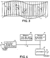
- the signs X represent the characteristic points in the image on turn n-1
- the round and solid signs represent the points predicted according to the relation (10) according to the characteristic points of turn n-1 and the angles ⁇ , ⁇ and ⁇ estimated a priori
- the square signs represent the characteristic points found in the image in turn n associated with the predicted points mentioned above
- the spaces delimited by dotted lines represent the search neighborhoods around the predicted points.
- the number of detections is not too large, so there are not often conflicts of assignments so that we can ignore the ambiguous measures.
- stage 5 It is from the points represented in FIG. 3 by solid circles and squares and mapped or associated during stage 4 that the Kalman filter will operate in stage 5.
- This last stage consists in the use of the Kalman filter applied to the estimation of the instantaneous parameters of the strain starting from the measurements of the deviations between the predicted characteristic points and those obtained in the current image which are associated with them following the matching of step 4 of matching.
- the image data is taken into account by an input bus 8 connected to a characteristic point extractor circuit 9, the latter can for example be an integrated VLSI circuit, following the Anglo-Saxon terminology "very large scale integration".
- the output of circuit 9 is connected to a bus 13 connecting a processor 12, a program and working memory 11 containing in particular the algorithms for calculating the Kalman filter, and a memory of RAM type for example containing the list of characteristic points.
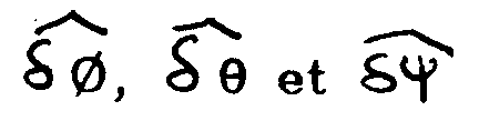
- the processor 12 delivers by an output bus 14 the estimated deformation parameters, for example the estimation of the variations of the angular parameters of the watch device.
- a first variant consists in replacing the method of tracking the characteristic points used in step 4 of matching by a correlation method.
- the prediction of the line of sight of the optical head is used to predict the position of the image.
- the accuracy of registration is increased and, above all, the problem of initialization is simplified.
- the problem of selecting the characteristic points is avoided: the points can be taken at random or periodically.
- the accuracy of the correlation is expressed by a covariance matrix of the measurement error deduced from the correlation results. This matrix intervenes in the recalibration equation of the Kalman filter.
- a second variant does not take into account the angular variations of the line of sight ⁇ , ⁇ and ⁇ , but seeks to directly estimate the angles of the line of sight and the angular positions of the characteristic points. This amounts to estimating ⁇ , ⁇ , ⁇ and the angular coordinates (u i , v i ) of the characteristic points, i being between 1 and n, number of characteristic points.
- the estimated position of the point identified by (u i , v i ) will be precise. It should be noted however that the knowledge of the absolute angles ⁇ , ⁇ and ⁇ is not essential for the registration, indeed the knowledge of the variations of angles ⁇ , ⁇ and ⁇ is enough. On the other hand, it improves the tracking of the targets because it allows to use a more precise dynamic model because we have a precise estimate of the angles.
- a third variant makes it possible to improve the estimation of the deformation parameters provided, however, that a delay in the estimation of these parameters is tolerated.
- Kalman filtering only takes into account past measurements. Taking into account future measurements, this estimate can be improved by the known Raugh smoothing technique, for example, a description of which can be found in the work by MM. Labarrere, J.P. Krief and B. Gimonet "Filtering and its applications" by Cepadues, Toulouse. This amounts, in a way, to interpolate the instantaneous image deformation parameters by relying on measurement points located on either side of this column.
Landscapes
- Physics & Mathematics (AREA)
- Engineering & Computer Science (AREA)
- Electromagnetism (AREA)
- General Physics & Mathematics (AREA)
- Radar, Positioning & Navigation (AREA)
- Remote Sensing (AREA)
- Computer Networks & Wireless Communication (AREA)
- Multimedia (AREA)
- Image Analysis (AREA)
- Image Processing (AREA)
- Length Measuring Devices By Optical Means (AREA)
Abstract
Description
- La présente invention concerne un procédé et un dispositif de recalage continu d'image en veille panoramique. Elle s'applique notamment aux systèmes d'imagerie panoramique pour la surveillance. L'image peut appartenir au domaine des longueurs d'onde visible ou infrarouge. Plus généralement, l'invention concerne les domaines du traitement d'images, de l'optronique et du traitement du signal. Elle peut par exemple s'appliquer au recalage des données obtenues par un radar de veille panoramique.
- Les systèmes d'imagerie panoramique permettent une surveillance selon un angle de 360°. Ils sont constitués d'une tête optique tournante et d'un détecteur linéaire. A chaque instant, le détecteur linéaire forme une colonne de l'image panoramique. L'image panoramique est obtenue par la juxtaposition des colonnes d'images formées par ce capteur linéaire en rotation autour d'un axe vertical. Le nombre de colonnes par tour peut atteindre plusieurs dizaines de milliers. Le recalage d'images consiste à mettre en correspondance les images successives obtenues durant les tours successifs du capteur. Le recalage d'images est par exemple nécessaire dans le cas de détection de mouvement ou de poursuite d'objets en déplacement. En effet, pour détecter les mouvements révélateurs de cibles ou de menaces potentielles, il faut procéder par analyse de la différence entre l'image courante et l'image formée au tour précédent. Or ce problème est compliqué par les propres mouvements ou oscillations du dispositif de veille, à savoir la tête optique tournante et le détecteur linéaire, inhérents à certaines applications. C'est le cas notamment quand ce dispositif est installé sur un porteur mobile ou au sommet d'un mât par exemple.
- Le problème à résoudre consiste donc à mettre au point un procédé permettant d'estimer de façon précise les déformations des images obtenues par le dispositif de veille tournant afin de rendre possible la détection d'objets en mouvement par différence entre l'image présente et l'image précédente corrigée de sa déformation. Des solutions connues utilisent des techniques de recalage global, comme celle décrite par l'article "Recursive motion estimation based on a model of the camera dynamics" paru dans la revue Signal Processing V : Theoric and Applications (L. Torres, E. Margrau et M.A. Lagunnas éditeur). D'autres solutions sont applicables lorsque chaque image est obtenue de façon quasi instantanée, sur imagerie de type télévision par exemple, et que la déformation peut être réduite à une transformation paramétrique globale telle qu'une translation-rotation en deux dimensions ou en trois dimensions en utilisant des modèles de profondeur de la scène. Des techniques non paramétriques fondées sur la recherche de transformations élastiques utilisant une hypothèse de continuité de la déformation sont parfois applicables. Néanmoins, des défauts apparaissent avec ces solutions, en particulier une imprécision de la mise en correspondance des images et une lourdeur des calculs.
- Le but de l'invention est de pallier les inconvénients précités.
- A cet effet, l'invention a pour objet un procédé de recalage continu d'images en veille panoramique utilisant des points caractéristiques extraits de l'image en cours et des points caractéristiques prédits à partir de l'image précédente caractérisé en ce qu'il consiste à utiliser un filtre de Kalman pour estimer les paramètres instantanés de déformation de l'image à partir des mesures des écarts entre les points caractéristiques prédits et ceux obtenus dans l'image en cours.
- L'invention a également pour objet un dispositif pour la mise en oeuvre du procédé précité.
- L'invention a pour principaux avantages qu'elle permet un recalage d'images compatible avec les applications de surveillances, notamment la détection et la caractérisation des mouvements d'objets en veille panoramique tout en réduisant la complexité des calculs de résolution.
- D'autres caractéristiques et avantages de l'invention apparaîtront à l'aide de la description qui suit faite en regard des dessins annexés qui représentent :
- La figure 1, un organigramme pour illustrer les étapes du procédé mis en oeuvre par l'invention.
- Les figures 2a et 2b, des représentations des différents repères utilisés.
- La figure 3, des images générées en deux tours successifs et représentées en superposition.
- La figure 4, un mode de réalisation possible d'un dispositif pour la mise en oeuvre de l'invention.
- Comme le montre l'organigramme de la figure 1, le procédé selon l'invention comporte cinq étapes. Ce procédé utilise la structure particulière des images panoramiques qui est continue et fermée, c'est-à-dire qu'il n'y a ni bord droit, ni bord gauche. Il utilise par ailleurs la connaissance a priori que l'on peut avoir sur les mouvements du dispositif de veille, connaissance de nature statistique aisément représentable par un modèle Gaussien-Markovien. Le procédé consiste suivant une étape 1 à extraire les points caractéristiques de l'image panoramique, suivant une étape 2 à gérer la liste des points caractéristiques, suivant une étape 3 à prédire les paramètres instantanés de la déformation a priori selon la technique du filtre de Kalman, suivant une étape 4 à mettre en correspondance les points caractéristiques qui viennent d'être extraits de l'image actuelle avec la liste des points caractéristiques prédits à partir de ceux de l'image précédente et des paramètres de déformation estimés a priori lors de l'étape 3, enfin suivant une étape 5 à estimer les paramètres instantanés de la déformation à partir des mesures des écarts entre les points caractéristiques prédits et ceux obtenus dans l'image courante, au moyen d'un filtre de Kalman. Cette dernière étape constitue le recalage d'images. La technique de filtrage de Kalman utilisée dans le procédé est bien connue de l'homme de l'art, elle est décrite en particulier dans l'ouvrage de MM. Labarrere, J.P. Krief et B. Gimonet "Le filtrage et ses applications" aux éditions Cepadues, Toulouse.
- L'étape 4 de mise en correspondance peut être décomposée en une étape de sélection des points caractéristiques parmi la liste établie suivi de l'étape de mise en correspondance. Par ailleurs, pour effectuer la détection d'objets mobiles, il est nécessaire d'ajouter une sixième étape de compensation de la déformation de l'image de référence pour qu'elle devienne superposable à l'image présente. Cette compensation est effectuée par la mise en oeuvre de la transformation paramétrique estimée à l'étape précédente 5. Les techniques d'extraction des points caractéristiques utilisées dans l'étape 1 ne sont pas développées parce qu'elles relèvent de méthodes connues. Il est possible par exemple d'extraire de l'image courante des points caractéristiques d'un tour à l'autre à l'aide du détecteur de Moravec, exposé dans l'article de H.P. Moravec "Towards automatic visual obstacle avoidance", in Proceding of the International Joint Conference on Artificial Intelligence (IJCAI), 1977. Dans l'étape 2, de gestion de la liste des points caractéristiques, les points extraits au tour présent sont mémorisés pour être utilisés lors de la mise en correspondance du tour suivant. Cette étape ne constituant pas une caractéristique de l'invention ne sera plus amplement décrite.
- Les paramètres de déformation estimés par le filtre de Kalman peuvent être par exemple les trois angles qui définissent à chaque instant l'orientation du dispositif tournant de veille panoramique. Dans ce cas, l'étape 3 consistera donc à prédire les angles de visée de ce dispositif de veille. Ces trois angles sont notés ⌀, ϑ et ψ. Ils sont indiqués sur les figures 2a et 2b qui montrent la représentation des différents repères utilisés et décrits ci-après.
- Soit figure 2a R = (O, x, y, z) un repère orthonormé, fixe de référence et
R₁ = (O, x₁, y₁, z₁) un repère orthonormé lié à la plate -forme supportant le dispositif de veille. Cette plate-forme peut être un porteur mobile ou le sommet d'un mât par exemple. - Soit figure 2b R₂ = (O, x₂, y₂, z₂) un repère orthonormé lié au dispositif de veille et tournant avec ce dispositif autour de l'axe Oz₁ du repère R₁ à la vitesse angulaire ω, dans ce repère R₂, l'axe 0x₂ matérialise l'axe optique du dispositif et
(O, u, v) le repère Ru,v définissant l'espace de dimension deux lié à l'image panoramique. Dans ce dernier repère, l'axe "horizontal" u indique la position de chaque colonne de l'image panoramique, proportionnel à ωt, où t représente le temps. Un point de l'espace défini dans le repère R₂ est vu à l'instant t tel que y₂ = 0 avec une ordonnée v telle que v/f = z₂/x₂, f étant la distance focale de la ligne de visée de la tête optique tournante. Pour des commodités de calculs, f sera pris égale à 1. - Soit ROT1 la matrice de passage du repère R au repère R₁ et ROT2 la matrice de passage du repère R₁ au repère R₂.
- Soit X = t(x, y, z) la matrice des coordonnées d'un point dans le repère R où tX désigne la transposée de la matrice X
Soit X₂ = t(x₂, y₂, z₂) la matrice des coordonnées d'un point dans le repère R₂. - D'après les définitions précédentes, 11 vient :
X₂ = ROT2*ROT1*X, produit matriciel de ROT1, ROT2 et de la matrice transposée de X.
ROT1 est définie à partir des angles ⌀, ϑ et ψ comme suit :
Les paramètres de la matrice ROT1 constituent un développement du premier ordre des coordonées du repère R₁ dans le repère R. Cette approximation est satisfaisante puisque ⌀, ϑ et ψ sont petits. Cette matrice est indépendante de l'ordre des rotations et elle est unitaire au premier ordre près, donc orthonormée. ROT2 est définie comme suit :
Le système à estimer selon la méthode du filtre de Kalman doit être décrit par un vecteur d'état. Il a été choisi ici le vecteur X = t(δ⌀, δϑ, δψ), vecteur des variations angulaires de ligne de visée de la tête optique d'un tour au suivant, défini par le passage sur le même point. L'évolution du système est décrite par un modèle de dynamique, en général de type Gaussien-Markovien représenté sous forme matricielle par l'équation X′= f(X)+w, où X′ est la dérivée du vecteur d'état X par rapport au temps, f(X) une fonction de X et w un bruit excitateur représentant les fluctuations aléatoires de l'état et caractérisé par la matrice de covariance de ce bruit, cette équation est linéarisée et devient X′ = F*X+w (1), F*X étant le produit matriciel de la matrice F définie selon le filtre de Kalman et du vecteur d'état X. Cette méthode permet ici de prédire les fonctions de densité de probabilité des angles φ, ϑ et ψ et donc de fournir une estimée a priori de ces angles à l'instant t, prenant en compte de façon optimale toutes les mesures passées. Le bruit a une densité de probabilité gaussienne. Plus ce bruit est grand, moins la prédiction est précise. - A partir de l'estimée a priori de ces paramètres, il est possible de prédire la position des points de recalage dans l'image. On recherche les points correspondants dans un voisinage de ces prédictions. L'association des points détectés dans l'image courante avec les points de référence est faite dès que l'on trouve un point non ambigu détecté dans l'image courante et dans le voisinage de recherche. Cette mise en correspondance, qui constitue l'étape 4, fait apparaître un écart entre la position trouvée et la position prédite : cet écart constitue la mesure grâce à laquelle les paramètres angulaires de la ligne de visée de la tête optique peuvent être recalés au cours de l'étape 5.
- Chaque point caractéristique de l'image panoramique est repéré par ses coordonnées u et v définies dans le repère Ru,v décrit précédemment. L'angle u correspond au numéro de colonne de l'image panoramique directement proportionnel au temps grâce à la relation u = ωt définie précédemment.
- Dans la suite (δu, δv) représente l'écart entre la position définie dans le repère Ru,v par (un, vn) et obtenue dans l'image en cours et la position (un₋₁, vn-1) obtenue dans l'image précédente pour le même point caractéristique.

- Soit T, l'écart de temps qui sépare la détection du tour n et celle du tour n-1, T est relié à δu par la relation suivante

cet angle est supposé petit
Soient


où
⌀(t+T) est la valeur de l'angle ⌀ au temps t+T
⌀(t) est la valeur de l'angle ⌀ au temps t, de même pour ϑ et ψ. - Les matrices de rotation ROT1 et ROT2 définies précédemment sont orthonormées, donc leurs matrices transposées sont aussi leurs matrices inverses. Les angles ⌀, ϑ et ψ étant fonctions du temps, ces matrices sont fonctions du temps. Si tROT1(t) et tROT2(t) sont les matrices transposées des matrices ROT1(t) et ROT2(t) fonctions du temps, il vient :

d'où est déduit la relation suivante
au premier ordre près, ce qui est possible puisque les angles ⌀, ϑ et ψ sont petits. - Il a été établi précédemment que v(t) = z₂(t)/x₂(t), en conséquence :

de l'équation (3), est également déduit :

enfin des relations (5) et (6) il découle :
- L'équation (4) est linéaire en δ⌀, δϑ et δψ. De plus si le point caractéristique est près de la ligne centrale (v=0), δu=δψ. Autrement dit, dans ce cas, l'écart en nombre de colonnes est directement proportionnel à l'écart angulaire autour de l'axe vertical. L'équation (7) est homographique en δ⌀, δϑ et δψ mais peut se linéariser si v est sensiblement nul. Dans ce cas :

- En réalité, les angles de visée sont petits, les points caractéristiques sont donc tels que v est sensiblement nul, il est donc possible, après linéarisation d'écrire les équations de mesure en utilisant le formalisme du filtre de Kalman :
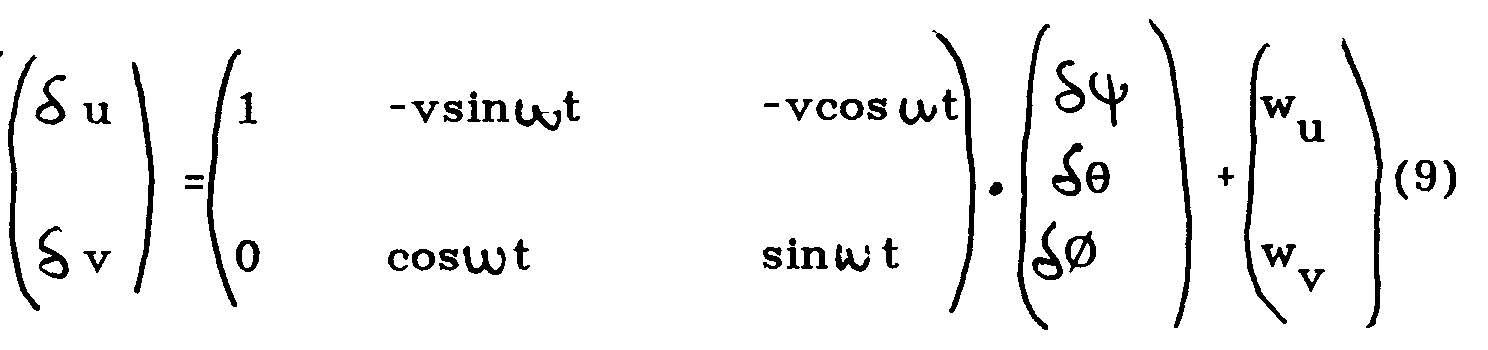
où (wu , wv) représente le bruit de mesure. - Cette relation matricielle suivant le formalisme du filtre de Kalman crée un lien entre le vecteur d'état (δψ, δϑ, δ⌀) et la mesure définie par (δu, δv). Cette relation sera utilisée lors de l'étape 5 pour définir l'estimation optimale du vecteur d'état à partir de la mesure (δu, δv).
- Auparavant, dans l'étape 4 de mise en correspondance, en utilisant la relation (9), à partir des valeurs prédites des variations a priori des angles ⌀, ϑ et ψ, il est possible de prédire la position dans l'image courante des points caractéristiques extraits au tour précédent en appliquant la relation :

le signe ^ indique que les valeurs sont estimées. - (un-1, vn-1) est un vecteur de coordonnées connues, puisque définies au tour précédent.
- Le vecteur

indique la position théorique estimée a priori du point caractéristique que l'on devrait trouver. - L'étape 4 consiste ensuite à mettre en correspondance les points caractéristiques de l'image en cours avec ceux du tour précédent par une méthode de pistage, c'est-à-dire par la recherche dans la liste des points caractéristiques de l'image courante, des points qui se projettent dans les voisinages des points prédits selon la relation (10) à partir des points caractéristiques de l'image précédente et de l'estimée a priori des paramètres angulaires de visée. La taille des voisinages dépend de l'incertitude de l'estimation. Cette mise en correspondance est illustrée par la figure 3. Sur cette figure apparaissent l'image 6 prise au tour n-1 et l'image déformée 7 prise au tour n superposée à la précédente. Les signes X représentent les points caractéristiques dans l'image au tour n-1, les signes ronds et pleins représentent les points prédits suivant la relation (10) d'après les points caractéristiques du tour n-1 et les angles ⌀, ϑ et ψ estimés a priori, les signes carrés représentent les points caractéristiques trouvés dans l'image au tour n associés aux points prédits cités précédemment, enfin les espaces délimités par des traits pointillés représentent les voisinages de recherche autour des points prédits. Dans la pratique le nombre de détections n'est pas trop important, il n'y a donc pas souvent de conflits d'affectations de sorte que l'on peut ignorer les mesures ambiguës.
- C'est à partir des points représentés sur la figure 3 par des ronds pleins et des carrés et mis en correspondance ou associés au cours de l'étape 4 que le filtre de Kalman va opérer dans l'étape 5. Cette dernière étape consiste en l'utilisation du filtre de Kalman appliqué à l'estimation des paramètres instantanés de la déformation à partir des mesures des écarts entre les points caractéristiques prédits et ceux obtenus dans l'image courante qui leurs sont associés suivant la mise en correspondance de l'étape 4 de mise en correspondance.
- En effet, par application du filtre de Kalman et grâce à l'équation de mesure (9) définie selon ce formalisme, il est possible de déduire des écarts mesurés et définis par les vecteurs (δu, δv), l'estimée optimale du vecteur d'état

estimée dite à posteriori, (δ⌀, δϑ, δψ) représentant la variation des paramètres angulaires de déformation entre deux tours successifs. L'estimation optimale de cette variation permet le recalage continu de l'image en veille panoramique. - Un mode de réalisation possible est représenté par la figure 4. Les données de l'image sont prises en compte par un bus d'entrée 8 relié à un circuit extracteur de points caractéristiques 9, ce dernier peut par exemple être un circuit intégré VLSI, suivant la terminologie anglo-saxonne "very large scale integration". La sortie du circuit 9 est reliée à un bus 13 reliant un processeur 12, une mémoire de programme et de travail 11 contenant notamment les algorithmes de calcul du filtre de Kalman, et une mémoire de type RAM par exemple contenant la liste des points caractéristiques. Le processeur 12 délivre par un bus de sortie 14 les paramètres de déformation estimés, par exemple l'estimation des variations des paramètres angulaires
du dispositif de veille. - Plusieurs variantes peuvent être appliquées au procédé selon l'invention. Une première variante consiste à remplacer la méthode de pistage des points caractéristiques utilisée dans l'étape 4 de mise en correspondance par une méthode de corrélation. Dans ce cas, au lieu de mettre en correspondance les listes de points caractéristiques de l'image présente avec celle du tour précédent, 11 est possible d'effectuer une corrélation d'images : la prédiction de la ligne de visée de la tête optique est utilisée pour prédire la position de l'image. La précision du recalage est augmentée et, surtout, le problème de l'initialisation est simplifié. De plus, le problème de la sélection des points caractéristiques est évité : les points peuvent être prélevés au hasard ou périodiquement. La précision de la corrélation s'exprime par une matrice de covariance de l'erreur de mesure déduite des résultats de corrélation. Cette matrice intervient dans l'équation de recalage du filtre de Kalman.
- Une deuxième variante ne prend pas en compte les variations angulaires de la ligne de visée δ⌀,δϑ et δψ, mais cherche à estimer directement les angles de la ligne de visée et les positions angulaires des points caractéristiques. Cela revient à estimer ⌀, ϑ, ψ et les coordonnées angulaires (ui, vi) des points caractéristiques, i étant compris entre 1 et n, nombre de points caractéristiques.
- Ces coordonnées angulaires sont mesurées à chaque tour par les équations de mesure de la forme :


où (uim, vim) est la mesure du point caractéristique de rang i. - Dans ce cas ϑ et ⌀ ne sont plus nécessairement des petits angles.
- Il est possible cependant de linéariser ces équations autour de la prédiction. Le filtrage de Kalman Etendu s'applique alors sur un vecteur d'état à 2n+3 paramètres au lieu de 3 : (φ, ϑ, ψ, u₂, v₁, ... un, vn). La dynamique des positions des points caractéristiques est plus simple puisqu'il suffit de considérer ces points comme fixes.
- Au bout d'un certain nombre de tours, la position estimée du point repéré par (ui, vi) sera précise. Il faut noter cependant que la connaissance des angles absolus ⌀, ϑ et ψ n'est pas indispensable pour le recalage, en effet la connaissance des variations d'angles ⌀, ϑ et ψ suffit. En revanche, elle améliore le pistage des cibles car elle permet d'utiliser un modèle de dynamique plus précis du fait que l'on dispose d'une estimation précise des angles.
- Enfin, une troisième variante permet d'améliorer l'estimation des paramètres de déformation à condition toutefois de tolérer un retard à l'estimation de ces paramètres. En effet, le filtrage de Kalman ne tient compte que des mesures passées. En tenant compte des mesures futures cette estimation peut être améliorée par la technique connue de lissage de Raugh par exemple dont une description peut être trouvée dans l'ouvrage de MM. Labarrere, J.P. Krief et B. Gimonet "Le filtrage et ses applications " aux éditions Cepadues, Toulouse. Cela revient, en quelque sorte, à interpoler les paramètres instantanées de déformation d'image en s'appuyant sur des points de mesures situés de part et d'autre de cette colonne.
Claims (5)
- Procédé de recalage continu d'images en veille panoramique utilisant des points caractéristiques extraits de l'image courante (1) et des points caractéristiques prédits à partir de l'image précédente, les images étant formées à partir d'un système de détection, caractérisé en ce qu'il consiste à utiliser un filtre de Kalman pour estimer les paramètres instantanés de déformation de l'image (5) à partir des mesures des écarts entre les points caractéristiques prédits et ceux obtenus dans l'image courante.
- Procédé selon la revendication 1, caractérisé en ce qu'il consiste à prédire les paramètres instantanés de déformation a priori (3) selon la technique du filtre de Kalman.
- Procédé selon l'une quelconque des revendications 1 ou 2, caractérisé en ce que les paramètres instantanés de déformation sont trois angles définissant à chaque instant l'orientation du système de détection par rapport à un repère fixe de référence.
- Procédé selon l'une quelconque des revendications précédentes, caractérisé en ce qu'il met en correspondance par une méthode de pistage (4) les points caractéristiques de l'image en cours avec les points caractéristiques prédits à partir de ceux de l'image précédente et des paramètres de déformation estimés a priori (3).
- Dispositif pour la mise en oeuvre du procédé selon l'une quelconque des revendications précédentes, caractérisé en ce qu'il est constitué d'un circuit comprenant au moins un processeur (12), un extracteur de points caractéristique (9), une mémoire de programme et de travail (11) et une mémoire contenant la liste des points caractéristiques (10) reliés par un même bus (13).
Applications Claiming Priority (2)
| Application Number | Priority Date | Filing Date | Title |
|---|---|---|---|
| FR9107672A FR2678088B1 (fr) | 1991-06-21 | 1991-06-21 | Procede et dispositif de recalage continu d'images en veille panoramique. |
| FR9107672 | 1991-06-21 |
Publications (2)
| Publication Number | Publication Date |
|---|---|
| EP0519773A1 true EP0519773A1 (fr) | 1992-12-23 |
| EP0519773B1 EP0519773B1 (fr) | 1997-03-12 |
Family
ID=9414150
Family Applications (1)
| Application Number | Title | Priority Date | Filing Date |
|---|---|---|---|
| EP92401384A Expired - Lifetime EP0519773B1 (fr) | 1991-06-21 | 1992-05-21 | Procédé et dispositif de recalage continu d'images en veille panoramique |
Country Status (3)
| Country | Link |
|---|---|
| EP (1) | EP0519773B1 (fr) |
| DE (1) | DE69218052D1 (fr) |
| FR (1) | FR2678088B1 (fr) |
Cited By (1)
| Publication number | Priority date | Publication date | Assignee | Title |
|---|---|---|---|---|
| US20090249787A1 (en) * | 2006-11-13 | 2009-10-08 | Deutsches Zentrum Fuer Luft- Und Raumfahrt E. V. | Method for controlling the alignment of a heliostat with respect to a receiver, heliostat device and solar power plant |
Citations (5)
| Publication number | Priority date | Publication date | Assignee | Title |
|---|---|---|---|---|
| WO1979000260A1 (fr) * | 1977-11-02 | 1979-05-17 | Saab Scania Ab | Suiveur de correlation pour pister un objet |
| US4688091A (en) * | 1986-05-06 | 1987-08-18 | Ford Aerospace & Communications Corporation | Spacecraft camera image registration |
| EP0241983A1 (fr) * | 1986-04-15 | 1987-10-21 | Laboratoires D'electronique Philips | Dispositif de traitement d'images pour l'estimation du déplacement d'objets situés dans celles-ci |
| EP0390640A1 (fr) * | 1989-03-29 | 1990-10-03 | General Electric Cgr S.A. | Procédé de recalage automatique d' images |
| FR2656106A1 (fr) * | 1988-12-12 | 1991-06-21 | Thomson Csf | Procede et dispositif d'acquisition automatique de cibles. |
-
1991
- 1991-06-21 FR FR9107672A patent/FR2678088B1/fr not_active Expired - Lifetime
-
1992
- 1992-05-21 DE DE69218052T patent/DE69218052D1/de not_active Expired - Lifetime
- 1992-05-21 EP EP92401384A patent/EP0519773B1/fr not_active Expired - Lifetime
Patent Citations (5)
| Publication number | Priority date | Publication date | Assignee | Title |
|---|---|---|---|---|
| WO1979000260A1 (fr) * | 1977-11-02 | 1979-05-17 | Saab Scania Ab | Suiveur de correlation pour pister un objet |
| EP0241983A1 (fr) * | 1986-04-15 | 1987-10-21 | Laboratoires D'electronique Philips | Dispositif de traitement d'images pour l'estimation du déplacement d'objets situés dans celles-ci |
| US4688091A (en) * | 1986-05-06 | 1987-08-18 | Ford Aerospace & Communications Corporation | Spacecraft camera image registration |
| FR2656106A1 (fr) * | 1988-12-12 | 1991-06-21 | Thomson Csf | Procede et dispositif d'acquisition automatique de cibles. |
| EP0390640A1 (fr) * | 1989-03-29 | 1990-10-03 | General Electric Cgr S.A. | Procédé de recalage automatique d' images |
Non-Patent Citations (1)
| Title |
|---|
| IEEE TRANSACTIONS ON AUTOMATIC CONTROL. vol. AC-25, no. 2, Avril 1980, NEW YORK US pages 222 - 225; P.S. MAYBECK ET AL.: 'A Target Tracker using spatially distributed Measurements' * |
Cited By (2)
| Publication number | Priority date | Publication date | Assignee | Title |
|---|---|---|---|---|
| US20090249787A1 (en) * | 2006-11-13 | 2009-10-08 | Deutsches Zentrum Fuer Luft- Und Raumfahrt E. V. | Method for controlling the alignment of a heliostat with respect to a receiver, heliostat device and solar power plant |
| US8651100B2 (en) * | 2006-11-13 | 2014-02-18 | Deutsches Zentrum Fuer Luft- Und Raumfahrt E.V. | Method for controlling the alignment of a heliostat with respect to a receiver, heliostat device and solar power plant |
Also Published As
| Publication number | Publication date |
|---|---|
| FR2678088A1 (fr) | 1992-12-24 |
| FR2678088B1 (fr) | 1995-03-03 |
| DE69218052D1 (de) | 1997-04-17 |
| EP0519773B1 (fr) | 1997-03-12 |
Similar Documents
| Publication | Publication Date | Title |
|---|---|---|
| JP7556142B2 (ja) | 点群からの効率的な三次元物体検出 | |
| EP2572319B1 (fr) | Procede et systeme pour fusionner des donnees issues de capteurs d'images et de capteurs de mouvement ou de position | |
| EP1329850B1 (fr) | Appareil, programme et méthode pour détecter des objets stationnaires et des objets en mouvement dans une image | |
| EP2851870B1 (fr) | Procédé pour l'estimation de l'ego-mouvement d'un objet | |
| US9330471B2 (en) | Camera aided motion direction and speed estimation | |
| TW202008308A (zh) | 單目圖像深度估計方法及裝置、設備、程式及儲存介質 | |
| WO2020104423A1 (fr) | Procédé et appareil de fusion de données de données lidar et de données d'image | |
| EP3955209B1 (fr) | Approche basée sur l'apprentissage machine et la vision pour la détection d'objets à vitesse zéro actualisée | |
| CN107743638A (zh) | 用于对tof传感器图像进行实时运动伪影处理和去噪的方法和系统 | |
| Bucci et al. | Comparison of feature detection and outlier removal strategies in a mono visual odometry algorithm for underwater navigation | |
| FR3091777A1 (fr) | Méthode de détermination d’un rayon de protection d’un système de navigation basé sur la vision | |
| WO2012175888A1 (fr) | Génération de données de carte | |
| EP0949588A1 (fr) | Procédé de recalage de deux images differentes d'un meme objet | |
| EP2927635B1 (fr) | Optimisation d'ensemble de caractéristiques de positionnement basé sur la vision | |
| WO2021167910A1 (fr) | Procédé de génération d'un ensemble de données, procédé de génération d'un réseau neuronal et procédé de construction d'un modèle d'une scène | |
| WO2025093064A2 (fr) | Procédé et système de ré-identification de position de véhicule | |
| EP0519773B1 (fr) | Procédé et dispositif de recalage continu d'images en veille panoramique | |
| CN107270904B (zh) | 基于图像配准的无人机辅助引导控制系统及方法 | |
| Lentz et al. | Image preprocessing to enhance phase correlation of featureless images | |
| Karnaukhov et al. | Analysis of linear distortion characteristics in problems of restoration of multispectral images | |
| Saidi et al. | A refined automatic co-registration method for high-resolution optical and sar images by maximizing mutual information | |
| Karthik et al. | Spatial aware feature extraction for RADAR SLAM | |
| KR102463522B1 (ko) | 고차수 이미지 분해 필터를 활용한 영상 기반의 구조물 움직임 측정 방법. | |
| Lakshmi et al. | Feature matching and assessment of similarity rate on geometrically distorted side scan sonar images | |
| FR3064069B1 (fr) | Controle non destructif de pieces aeronautiques par un systeme de radiographie |
Legal Events
| Date | Code | Title | Description |
|---|---|---|---|
| PUAI | Public reference made under article 153(3) epc to a published international application that has entered the european phase |
Free format text: ORIGINAL CODE: 0009012 |
|
| AK | Designated contracting states |
Kind code of ref document: A1 Designated state(s): DE GB IT |
|
| 17P | Request for examination filed |
Effective date: 19930327 |
|
| 17Q | First examination report despatched |
Effective date: 19950214 |
|
| GRAG | Despatch of communication of intention to grant |
Free format text: ORIGINAL CODE: EPIDOS AGRA |
|
| GRAH | Despatch of communication of intention to grant a patent |
Free format text: ORIGINAL CODE: EPIDOS IGRA |
|
| GRAH | Despatch of communication of intention to grant a patent |
Free format text: ORIGINAL CODE: EPIDOS IGRA |
|
| RAP1 | Party data changed (applicant data changed or rights of an application transferred) |
Owner name: THOMSON-CSF |
|
| GRAA | (expected) grant |
Free format text: ORIGINAL CODE: 0009210 |
|
| AK | Designated contracting states |
Kind code of ref document: B1 Designated state(s): DE GB IT |
|
| PG25 | Lapsed in a contracting state [announced via postgrant information from national office to epo] |
Ref country code: IT Free format text: LAPSE BECAUSE OF FAILURE TO SUBMIT A TRANSLATION OF THE DESCRIPTION OR TO PAY THE FEE WITHIN THE PRE;WARNING: LAPSES OF ITALIAN PATENTS WITH EFFECTIVE DATE BEFORE 2007 MAY HAVE OCCURRED AT ANY TIME BEFORE 2007. THE CORRECT EFFECTIVE DATE MAY BE DIFFERENT FROM THE ONE RECORDED.SCRIBED TIME-LIMIT Effective date: 19970312 |
|
| REF | Corresponds to: |
Ref document number: 69218052 Country of ref document: DE Date of ref document: 19970417 |
|
| GBT | Gb: translation of ep patent filed (gb section 77(6)(a)/1977) |
Effective date: 19970422 |
|
| PG25 | Lapsed in a contracting state [announced via postgrant information from national office to epo] |
Ref country code: DE Effective date: 19970613 |
|
| PLBE | No opposition filed within time limit |
Free format text: ORIGINAL CODE: 0009261 |
|
| STAA | Information on the status of an ep patent application or granted ep patent |
Free format text: STATUS: NO OPPOSITION FILED WITHIN TIME LIMIT |
|
| 26N | No opposition filed | ||
| PGFP | Annual fee paid to national office [announced via postgrant information from national office to epo] |
Ref country code: GB Payment date: 20000418 Year of fee payment: 9 |
|
| PG25 | Lapsed in a contracting state [announced via postgrant information from national office to epo] |
Ref country code: GB Free format text: LAPSE BECAUSE OF NON-PAYMENT OF DUE FEES Effective date: 20010521 |
|
| GBPC | Gb: european patent ceased through non-payment of renewal fee |
Effective date: 20010521 |