EP0519783A1 - Verfahren und Vorrichtung zur Lieferung von Gas an einer Analysevorrichtung mit hoher Empfindlichkeit - Google Patents
Verfahren und Vorrichtung zur Lieferung von Gas an einer Analysevorrichtung mit hoher Empfindlichkeit Download PDFInfo
- Publication number
- EP0519783A1 EP0519783A1 EP92401595A EP92401595A EP0519783A1 EP 0519783 A1 EP0519783 A1 EP 0519783A1 EP 92401595 A EP92401595 A EP 92401595A EP 92401595 A EP92401595 A EP 92401595A EP 0519783 A1 EP0519783 A1 EP 0519783A1
- Authority
- EP
- European Patent Office
- Prior art keywords
- mixture
- gas
- flow
- line
- stream
- Prior art date
- Legal status (The legal status is an assumption and is not a legal conclusion. Google has not performed a legal analysis and makes no representation as to the accuracy of the status listed.)
- Withdrawn
Links
- 238000000034 method Methods 0.000 title claims abstract description 20
- 230000035945 sensitivity Effects 0.000 title claims description 5
- 239000000203 mixture Substances 0.000 claims abstract description 62
- 239000007789 gas Substances 0.000 claims abstract description 52
- 239000012159 carrier gas Substances 0.000 claims abstract description 16
- 238000007865 diluting Methods 0.000 claims abstract 3
- XLYOFNOQVPJJNP-UHFFFAOYSA-N water Chemical compound O XLYOFNOQVPJJNP-UHFFFAOYSA-N 0.000 claims description 14
- 238000010790 dilution Methods 0.000 claims description 10
- 239000012895 dilution Substances 0.000 claims description 10
- IJGRMHOSHXDMSA-UHFFFAOYSA-N Atomic nitrogen Chemical compound N#N IJGRMHOSHXDMSA-UHFFFAOYSA-N 0.000 claims description 9
- 238000011144 upstream manufacturing Methods 0.000 claims description 9
- 229910052757 nitrogen Inorganic materials 0.000 claims description 4
- 239000007788 liquid Substances 0.000 claims description 2
- 238000000746 purification Methods 0.000 claims 1
- XKRFYHLGVUSROY-UHFFFAOYSA-N Argon Chemical compound [Ar] XKRFYHLGVUSROY-UHFFFAOYSA-N 0.000 description 6
- 238000009795 derivation Methods 0.000 description 5
- 229910052786 argon Inorganic materials 0.000 description 3
- OKTJSMMVPCPJKN-UHFFFAOYSA-N Carbon Chemical compound [C] OKTJSMMVPCPJKN-UHFFFAOYSA-N 0.000 description 2
- 239000011261 inert gas Substances 0.000 description 2
- 238000009434 installation Methods 0.000 description 2
- VNWKTOKETHGBQD-UHFFFAOYSA-N methane Chemical compound C VNWKTOKETHGBQD-UHFFFAOYSA-N 0.000 description 2
- 230000001105 regulatory effect Effects 0.000 description 2
- CURLTUGMZLYLDI-UHFFFAOYSA-N Carbon dioxide Chemical compound O=C=O CURLTUGMZLYLDI-UHFFFAOYSA-N 0.000 description 1
- 229910021536 Zeolite Inorganic materials 0.000 description 1
- 239000003463 adsorbent Substances 0.000 description 1
- 239000000356 contaminant Substances 0.000 description 1
- 238000010586 diagram Methods 0.000 description 1
- HNPSIPDUKPIQMN-UHFFFAOYSA-N dioxosilane;oxo(oxoalumanyloxy)alumane Chemical compound O=[Si]=O.O=[Al]O[Al]=O HNPSIPDUKPIQMN-UHFFFAOYSA-N 0.000 description 1
- 239000012535 impurity Substances 0.000 description 1
- 230000004048 modification Effects 0.000 description 1
- 238000012986 modification Methods 0.000 description 1
- 238000011084 recovery Methods 0.000 description 1
- 229910001220 stainless steel Inorganic materials 0.000 description 1
- 239000010935 stainless steel Substances 0.000 description 1
- 230000007704 transition Effects 0.000 description 1
- 239000010457 zeolite Substances 0.000 description 1
Images

Classifications
-
- G—PHYSICS
- G01—MEASURING; TESTING
- G01N—INVESTIGATING OR ANALYSING MATERIALS BY DETERMINING THEIR CHEMICAL OR PHYSICAL PROPERTIES
- G01N33/00—Investigating or analysing materials by specific methods not covered by groups G01N1/00 - G01N31/00
- G01N33/0004—Gaseous mixtures, e.g. polluted air
- G01N33/0009—General constructional details of gas analysers, e.g. portable test equipment
- G01N33/0011—Sample conditioning
- G01N33/0018—Sample conditioning by diluting a gas
-
- G—PHYSICS
- G01—MEASURING; TESTING
- G01N—INVESTIGATING OR ANALYSING MATERIALS BY DETERMINING THEIR CHEMICAL OR PHYSICAL PROPERTIES
- G01N33/00—Investigating or analysing materials by specific methods not covered by groups G01N1/00 - G01N31/00
- G01N33/0004—Gaseous mixtures, e.g. polluted air
- G01N33/0006—Calibrating gas analysers
Definitions
- the present invention relates to a method for supplying, to at least one high-sensitivity analyzer, small quantities of a first gas contained in a second gas, comprising the steps of dividing a primary flow of the second gas into a first flow and a second flow greater than the first flow, to introduce into the first flow a determined quantity of the first gas to constitute a first mixture, and to combine at least part of the second flow with the first mixture to constitute a second mixture available at a first outlet from use for supply to the analyzer.
- Modern techniques increasingly require capacities to detect very small quantities, which can go down to ppb (part per billion) of a first gas in a second gas.
- the very high sensitivity analyzers provided for this purpose present calibration problems which are difficult to solve, in particular for hygrometers.
- the known methods, of the type defined above, using a dilution of the first mixture with the second flow only make it possible to cover, at the end of use, only a limited range, the transition to another range requiring modification means for injecting into the first flow the determined quantity of the first gas.
- the object of the present invention is to propose a method which makes it possible, in a reliable, reproducible and modular manner, to cover, with a single system, flexible and inexpensive use, a wide range of calibration in outputs in several outputs, which can go down up to very low levels, less than 0.01 ppm (parts per million) enabling rapid operation and ensuring stable dilution rates in the various output mixtures.
- the method comprises the steps of dividing the second stream into a third stream, for combination with the first mixture, and a fourth stream, greater than the third stream, of taking a part of the second mixing before supply to the first outlet, and to combine at least part of the fourth stream with the part taken from the second mixture to constitute a third mixture available at a second use outlet for supply to an analyzer, the third mixture thus having a determined first gas content lower than that of the first mixture available at the first use outlet.
- the method further comprises the steps of dividing the fourth stream into a fifth stream for combination with the withdrawn portion of the second mixture, and a sixth stream greater than the fifth stream, of withdrawing a portion of the third mixture before delivery to the second outlet, to combine at least a portion of the sixth stream with the portion of the third mixture to form a fourth mixture available at a third outlet, typically to divide the sixth stream into a seventh stream, for combination with the withdrawn portion of the third mixture , and an eighth stream greater than the seventh stream, to take a part of the fourth mixture before supply to the third outlet, to combine at least part of the seventh stream with the withdrawn part of the fourth mixture to form a fifth mixture available at a fourth outlet , and advantageously to divide the eighth stream into a ninth f lux, for combination with the withdrawn part of the fourth mixture, and a tenth flow, to take part of the fourth mixture before supply to the third outlet, to pass the tenth flow through a separator, typically a cryogenic trap for supply of a standard mixture, via a separator
- the present invention also relates to a device for supplying gas to at least one very high sensitivity analyzer for implementing the above method, of the type comprising a second gas source supplying a first line comprising a means for introducing the second gas, and a second line connected to the first line downstream of the introduction means and ending in a first outlet section connectable to the analyzer, characterized in that the second line divides into a third line connected to a first branch coming from the first output section and ending in a second output section connectable to the analyzer.
- the second line divides a fourth line connected to a second branch coming from the second outlet section and ending in a third outlet section, the second line typically dividing into a fifth line connected to a third branch of the third outlet section and ending in a fourth outlet section connectable to the analyzer, the second line advantageously dividing into a sixth line, crossing a cryogenic trap, connected to the third branch and ending in a fifth connectable outlet section to the analyzer.
- the introduction means consists of a thermostatically controlled saturator with a water surface, advantageously with a double envelope and pressure controlled.
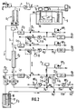
- a flow Q of a carrier gas coming from a source 100 feeds a first line 1, comprising a station S for introduction a small determined quantity of an analysis gas A in the carrier gas passing through the first line 1 and supplying a first gas mixture M1 is released.
- the source of carrier gas 100 also supplies a second line 2, provided with a first purifying device E1 downstream of which it is divided into a third line 3 connecting, in a first dilution station D1, to the first line 1 downstream of the device S for introducing the analysis gas A to end with a first outlet section T1 connectable, at U1 to an analyzer.
- the second line 2 is extended, downstream of the purifier E1 crosses a purifier E21 and is divided into a fifth line 5 connecting, in a second dilution station D2, to a first derivation d1 coming from the first outlet section S1 for end in a second output section TS2 connectable, in U2, to an analyzer.
- the second line 2 is extended by crossing a purifier E22 and is divided into a seventh line 7 connecting, in a third dilution station D3, to a second derivation d2 coming from the second outlet section TS2, to end in a third section TS3 output connector, in U3, to an analyzer.
- the second line is extended by crossing a purifier E se and is divided into a ninth line 9 and a tenth line 10.
- the ninth line 9 is connected, in a fourth dilution station D4, to a third derivation d3 coming from the third section TS3 for end in a fourth output section TS tron connectable, in U4, to an analyzer.
- the tenth line 10 ends in a fifth output section TS5 connectable, in U5, to an analyzer.
- the flow rates q1, q3, q5, q7, q9 and q10 in lines 1, 3, 5, 7, 9 and 10 are fixed by flow limiting means L1, L3, L5, L7, L9 and L10, respectively.
- the flow rates q11, q12, q13 in the branches d1, d2, d3 are fixed by flow limiting means L11, L12, L13, respectively.
- the purifiers E1 and E 2i are purifiers of the adsorbent type with zeolite and / or activated carbon to purify the carrier gas from its possible contaminants, water vapor, methane or CO2.
- the various tubes are made of internally electropolished stainless steel.
- the various flow limiting means L1 to L13 make it possible to guarantee constant determined flow rates at the various outputs U1 to U5 whatever the uses made of these different outputs. Therefore, two or more of these outputs, which offer different ranges, covering a wide range, of gas contents to be analyzed, can be used in parallel to calibrate or calibrate several analyzers simultaneously.
- FIG. 2 a device according to the invention in an application for the calibration of hygrometers.
- the supply pressure of the carrier gas system is provided, upstream of lines 1 and 2, by an upstream pressure regulator RP a .
- the gas to be analyzed A being water vapor
- the introduction device S here consists of a thermostatically controlled double jacket saturator providing a flat surface on the path of the gas in the first line 1 of water 15, the body of water being maintained by a water tank 16, the temperature and the pressure of the gaseous sky above the water table 15 being regulated at a pressure P S and a temperature T S saturation.
- the flow limiting means L1 in line 1 here consists of a flow regulator ensuring, at the outlet of the saturator S, a constant flow of the initial mixture of wet gas M1, which will be successively diluted by the carrier gas dry at dilution stations D1 to D5.
- the tenth line 10 comprises a purifier E3 consisting of a cryogenic trap with a heat exchanger 17 in a bath of liquid nitrogen 18 and the tenth line 10 is connected, in a fifth dilution station D5, to a fourth derivation d4 coming, like the third derivation d3, from the third section of TS3 outlet connected to the third U3 outlet, the fourth branch d4 being provided with a flow limiting means L14.
- the flow limiting means L3, L5, L7, L9, L10, L13 and L14 consist of fixed restrictors with a sonic neck while the flow limiting means L11 in the first branch d1 and L12 in the second branch d2 are made controllable flow regulators.
- the output sections TS1 to TS3 are associated with pressure regulators RP1, RP2 and RP3, respectively arranged in excess circulatory flow charge lines leading to the open air or in an excess mixture recovery capacity, while the fourth and fifth output sections TS4 and TS5 are each associated with a discharge flow regulator RD1 and RD2 in a corresponding discharge circuit.
- An arrangement of this type is described in document EP-A - 0.479.633, the content of which is assumed to be integrated here for reference.
- a pressure sensor P1 is provided upstream of the restrictions L3 and L5
- a pressure sensor P2 is provided upstream of the restrictions L7, L9 and L10
- a pressure sensor P3 is provided in the discharge line of the third section of TS3 outlet, upstream of the RP3 pressure regulator to detect the pressure in the third TS3 outlet section, upstream of the L13 and L14 restrictions in the d3 and d4 branches.
Landscapes
- Chemical & Material Sciences (AREA)
- Life Sciences & Earth Sciences (AREA)
- Engineering & Computer Science (AREA)
- Health & Medical Sciences (AREA)
- Analytical Chemistry (AREA)
- General Physics & Mathematics (AREA)
- Medicinal Chemistry (AREA)
- Physics & Mathematics (AREA)
- Combustion & Propulsion (AREA)
- Biochemistry (AREA)
- General Health & Medical Sciences (AREA)
- Food Science & Technology (AREA)
- Immunology (AREA)
- Pathology (AREA)
- Sampling And Sample Adjustment (AREA)
- Investigating Or Analyzing Materials By The Use Of Electric Means (AREA)
- Other Investigation Or Analysis Of Materials By Electrical Means (AREA)
- Investigating Or Analysing Materials By Optical Means (AREA)
Applications Claiming Priority (2)
| Application Number | Priority Date | Filing Date | Title |
|---|---|---|---|
| FR9107139A FR2677763B1 (fr) | 1991-06-12 | 1991-06-12 | Procede et dispositif de fourniture de gaz a un analyseur a haute sensibilite. |
| FR9107139 | 1991-06-12 |
Publications (1)
| Publication Number | Publication Date |
|---|---|
| EP0519783A1 true EP0519783A1 (de) | 1992-12-23 |
Family
ID=9413733
Family Applications (1)
| Application Number | Title | Priority Date | Filing Date |
|---|---|---|---|
| EP92401595A Withdrawn EP0519783A1 (de) | 1991-06-12 | 1992-06-10 | Verfahren und Vorrichtung zur Lieferung von Gas an einer Analysevorrichtung mit hoher Empfindlichkeit |
Country Status (4)
| Country | Link |
|---|---|
| US (1) | US5509292A (de) |
| EP (1) | EP0519783A1 (de) |
| JP (1) | JP3280701B2 (de) |
| FR (1) | FR2677763B1 (de) |
Cited By (4)
| Publication number | Priority date | Publication date | Assignee | Title |
|---|---|---|---|---|
| WO1994020851A1 (de) * | 1993-03-12 | 1994-09-15 | Siemens Aktiengesellschaft | Gasmischeinrichtung |
| EP0664449B1 (de) * | 1994-01-07 | 2000-06-14 | L'air Liquide, Societe Anonyme Pour L'etude Et L'exploitation Des Procedes Georges Claude | Verfahren und Vorrichtung zur Lieferung von Gas an eine Vorrichtung zur Analyse von Verunreinigungsspuren in einem Gas |
| WO2007031772A1 (en) * | 2005-09-15 | 2007-03-22 | The Secretary Of State For Defence | Apparatus and methods for dilution |
| EP2667190A3 (de) * | 2012-05-22 | 2013-12-04 | Horiba, Ltd. | Kalibriersystem für Analysegerät, und Abgasanalysegerät |
Families Citing this family (10)
| Publication number | Priority date | Publication date | Assignee | Title |
|---|---|---|---|---|
| US5907108A (en) * | 1996-08-26 | 1999-05-25 | University Of South Florida | Continuous sampling and dilution system and method |
| FR2755512B1 (fr) * | 1996-11-05 | 1998-12-18 | Air Liquide | Procede et dispositif de fourniture a un appareil d'un gaz pur charge d'une quantite predeterminee d'au moins une impurete gazeuse |
| JP3741603B2 (ja) | 2000-11-17 | 2006-02-01 | 寛治 大塚 | 配線基板 |
| US6729195B2 (en) * | 2001-05-10 | 2004-05-04 | Caterpillar Inc | Serial multistage aerosol diluter and control system |
| EP2235517B1 (de) * | 2007-12-31 | 2018-08-01 | O. I. Corporation | System und verfahren zur regulation des flusses in fluidvorrichtungen |
| JP5192350B2 (ja) * | 2008-10-30 | 2013-05-08 | 株式会社船井電機新応用技術研究所 | センサ評価システム |
| CN102240519A (zh) * | 2011-05-27 | 2011-11-16 | 中国计量科学研究院 | 标准气体的动态配气系统 |
| JP5889583B2 (ja) * | 2011-09-12 | 2016-03-22 | 株式会社豊田中央研究所 | 低濃度ガス供給装置 |
| JP6493441B2 (ja) * | 2017-03-27 | 2019-04-03 | 栗田工業株式会社 | 水質測定方法 |
| CN107008200A (zh) * | 2017-05-23 | 2017-08-04 | 淮海工学院 | 获取不同二氧化碳浓度的装置 |
Citations (2)
| Publication number | Priority date | Publication date | Assignee | Title |
|---|---|---|---|---|
| EP0370151A1 (de) * | 1988-11-21 | 1990-05-30 | L'air Liquide, Societe Anonyme Pour L'etude Et L'exploitation Des Procedes Georges Claude | Verfahren zum Herstellen von Gasgemischen niedriger Konzentration und Vorrichtung zu ihrer Herstellung |
| EP0370870A1 (de) * | 1988-11-21 | 1990-05-30 | L'air Liquide, Societe Anonyme Pour L'etude Et L'exploitation Des Procedes Georges Claude | Verfahren zum Herstellen von Gasgemischen geringer Konzentration und Vorrichtung zu ihrer Erzeugung |
Family Cites Families (3)
| Publication number | Priority date | Publication date | Assignee | Title |
|---|---|---|---|---|
| US4269057A (en) * | 1979-10-24 | 1981-05-26 | The United States Of America As Represented By The Secretary Of The Army | Multipurpose humidity controlled agent generator |
| US4385910A (en) * | 1981-12-23 | 1983-05-31 | Caterpillar Tractor Co. | Apparatus and method for producing a gas having a controlled water vapor content |
| JPS6066142A (ja) * | 1983-09-22 | 1985-04-16 | Shisaka Kenkyusho:Kk | 湿度計の校正装置 |
-
1991
- 1991-06-12 FR FR9107139A patent/FR2677763B1/fr not_active Expired - Fee Related
-
1992
- 1992-06-10 EP EP92401595A patent/EP0519783A1/de not_active Withdrawn
- 1992-06-12 US US07/898,192 patent/US5509292A/en not_active Expired - Fee Related
- 1992-06-12 JP JP15334592A patent/JP3280701B2/ja not_active Expired - Fee Related
Patent Citations (2)
| Publication number | Priority date | Publication date | Assignee | Title |
|---|---|---|---|---|
| EP0370151A1 (de) * | 1988-11-21 | 1990-05-30 | L'air Liquide, Societe Anonyme Pour L'etude Et L'exploitation Des Procedes Georges Claude | Verfahren zum Herstellen von Gasgemischen niedriger Konzentration und Vorrichtung zu ihrer Herstellung |
| EP0370870A1 (de) * | 1988-11-21 | 1990-05-30 | L'air Liquide, Societe Anonyme Pour L'etude Et L'exploitation Des Procedes Georges Claude | Verfahren zum Herstellen von Gasgemischen geringer Konzentration und Vorrichtung zu ihrer Erzeugung |
Non-Patent Citations (2)
| Title |
|---|
| MEASUREMENTS. vol. 1, no. 4, Octobre 1983, LONDON GB pages 172 - 176 H. UCHIYAMA, ET AL. 'THE TECHNIQUE OF PRODUCING REFERENCE-STANDARD GAS BY THE FLOW -MEASURING METHOD' * |
| PATENT ABSTRACTS OF JAPAN vol. 9, no. 203 (P-381)(1926) 21 Août 1985 & JP-A-60 066 142 ( SHISAKA KENKYUSHO K.K. ) 16 Avril 1985 * |
Cited By (8)
| Publication number | Priority date | Publication date | Assignee | Title |
|---|---|---|---|---|
| WO1994020851A1 (de) * | 1993-03-12 | 1994-09-15 | Siemens Aktiengesellschaft | Gasmischeinrichtung |
| US5614655A (en) * | 1993-03-12 | 1997-03-25 | Siemens Aktiengesellschaft | Gas mixing device |
| EP0664449B1 (de) * | 1994-01-07 | 2000-06-14 | L'air Liquide, Societe Anonyme Pour L'etude Et L'exploitation Des Procedes Georges Claude | Verfahren und Vorrichtung zur Lieferung von Gas an eine Vorrichtung zur Analyse von Verunreinigungsspuren in einem Gas |
| WO2007031772A1 (en) * | 2005-09-15 | 2007-03-22 | The Secretary Of State For Defence | Apparatus and methods for dilution |
| GB2445683A (en) * | 2005-09-15 | 2008-07-16 | Secr Defence | Apparatus and methods for dilution |
| GB2445683B (en) * | 2005-09-15 | 2010-10-13 | Secr Defence | Apparatus and methods for dilution |
| US7913535B2 (en) | 2005-09-15 | 2011-03-29 | The Secretary Of State For Defence In Her Britannic Majesty's Government Of The United Kingdom Of Great Britain And Northern Ireland | Apparatus and methods for dilution |
| EP2667190A3 (de) * | 2012-05-22 | 2013-12-04 | Horiba, Ltd. | Kalibriersystem für Analysegerät, und Abgasanalysegerät |
Also Published As
| Publication number | Publication date |
|---|---|
| US5509292A (en) | 1996-04-23 |
| FR2677763B1 (fr) | 1994-08-26 |
| JP3280701B2 (ja) | 2002-05-13 |
| FR2677763A1 (fr) | 1992-12-18 |
| JPH06174601A (ja) | 1994-06-24 |
Similar Documents
| Publication | Publication Date | Title |
|---|---|---|
| EP0519783A1 (de) | Verfahren und Vorrichtung zur Lieferung von Gas an einer Analysevorrichtung mit hoher Empfindlichkeit | |
| US5157957A (en) | Process for producing standard gas mixture and apparatus for producing the same | |
| EP0479633B1 (de) | Verfahren und Vorrichtung zur Lieferung von einem Gas an einen sehr empfindlichen Analysator | |
| US5239856A (en) | Apparatus for producing standard gas mixtures | |
| US10155180B2 (en) | Contacting systems and methods and uses thereof | |
| EP0358551B1 (de) | Verfahren und Vorrichtung zur Abtrennung eines Bestandteils einer Gasmischung | |
| EP1175933B1 (de) | Vorrichtung zur Gastrennung | |
| JPH0716591B2 (ja) | 低濃度ガス混合物の製造方法およびそのための装置 | |
| EP0748765B1 (de) | Anlage zur Herstellung von Kohlenmonoxid, welche eine kryogene Trennvorrichtung aufweist | |
| CA2443233C (fr) | Procede de traitement par adsorption d'un melange gazeux | |
| CA2188988A1 (fr) | Procede et installation de production d'hydrogene et d'energie | |
| EP0465298A1 (de) | Verfahren und Anlage zur Herstellung eines gasförmigen Bestandteils aus einer gasförmigen Mischung | |
| KR20000076504A (ko) | 가스중의 미량 불순물의 분석방법 및 장치 | |
| JPH05118453A (ja) | 向流弁 | |
| US20020011153A1 (en) | Gas separation apparatus | |
| US5376163A (en) | Filter system | |
| JPS5525659A (en) | Explosion-proof inert gas producing method in tanker | |
| EP0989899A1 (de) | Verfahren und vorrichtung für die zuführung meherer arbeitsgase und deren verwendung in einer anlage zur konstruktion von electronischen bauteilen | |
| US20030047068A1 (en) | Production method using permeation of at least two gaseous fluxes from a gaseous mixture, and a production installation for implementing this method | |
| KR100244917B1 (ko) | 반도체설비의 부속기구 분석장치 및 이를 이용한 분석방법 | |
| SU1122967A1 (ru) | Блок подготовки газов дл газового хроматографа | |
| NL2022204B1 (nl) | Werkwijze en inrichting voor het bepalen van de concentratie van een gasvormige verontreiniging in een productgas van zeer hoge zuiverheid | |
| FR3108524A1 (fr) | Atténuation des variations de débit, de pression et de masse molaire sur l’effluent gazeux d’un PSA | |
| SU1650800A1 (ru) | Способ подачи газов в реактор дл газофазной эпитаксии | |
| RU1784815C (ru) | Устройство дл глубокой очистки газов от примесей паров воды и кислорода |
Legal Events
| Date | Code | Title | Description |
|---|---|---|---|
| PUAI | Public reference made under article 153(3) epc to a published international application that has entered the european phase |
Free format text: ORIGINAL CODE: 0009012 |
|
| 17P | Request for examination filed |
Effective date: 19920615 |
|
| AK | Designated contracting states |
Kind code of ref document: A1 Designated state(s): DE FR GB IT |
|
| 17Q | First examination report despatched |
Effective date: 19950915 |
|
| STAA | Information on the status of an ep patent application or granted ep patent |
Free format text: STATUS: THE APPLICATION IS DEEMED TO BE WITHDRAWN |
|
| 18D | Application deemed to be withdrawn |
Effective date: 19960316 |