EP0519994B1 - Drainage- und erosionsverminderungssystem - Google Patents
Drainage- und erosionsverminderungssystem Download PDFInfo
- Publication number
- EP0519994B1 EP0519994B1 EP19910906291 EP91906291A EP0519994B1 EP 0519994 B1 EP0519994 B1 EP 0519994B1 EP 19910906291 EP19910906291 EP 19910906291 EP 91906291 A EP91906291 A EP 91906291A EP 0519994 B1 EP0519994 B1 EP 0519994B1
- Authority
- EP
- European Patent Office
- Prior art keywords
- tyre
- sectors
- drainage construction
- drainage
- construction
- Prior art date
- Legal status (The legal status is an assumption and is not a legal conclusion. Google has not performed a legal analysis and makes no representation as to the accuracy of the status listed.)
- Expired - Lifetime
Links
Images

Classifications
-
- E—FIXED CONSTRUCTIONS
- E01—CONSTRUCTION OF ROADS, RAILWAYS, OR BRIDGES
- E01C—CONSTRUCTION OF, OR SURFACES FOR, ROADS, SPORTS GROUNDS, OR THE LIKE; MACHINES OR AUXILIARY TOOLS FOR CONSTRUCTION OR REPAIR
- E01C11/00—Details of pavings
- E01C11/22—Gutters; Kerbs ; Surface drainage of streets, roads or like traffic areas
- E01C11/224—Surface drainage of streets
- E01C11/227—Gutters; Channels ; Roof drainage discharge ducts set in sidewalks
-
- E—FIXED CONSTRUCTIONS
- E02—HYDRAULIC ENGINEERING; FOUNDATIONS; SOIL SHIFTING
- E02B—HYDRAULIC ENGINEERING
- E02B11/00—Drainage of soil, e.g. for agricultural purposes
- E02B11/005—Drainage conduits
-
- E—FIXED CONSTRUCTIONS
- E02—HYDRAULIC ENGINEERING; FOUNDATIONS; SOIL SHIFTING
- E02B—HYDRAULIC ENGINEERING
- E02B2201/00—Devices, constructional details or methods of hydraulic engineering not otherwise provided for
- E02B2201/04—Devices, constructional details or methods of hydraulic engineering not otherwise provided for using old tires for hydraulic engineering
-
- Y—GENERAL TAGGING OF NEW TECHNOLOGICAL DEVELOPMENTS; GENERAL TAGGING OF CROSS-SECTIONAL TECHNOLOGIES SPANNING OVER SEVERAL SECTIONS OF THE IPC; TECHNICAL SUBJECTS COVERED BY FORMER USPC CROSS-REFERENCE ART COLLECTIONS [XRACs] AND DIGESTS
- Y02—TECHNOLOGIES OR APPLICATIONS FOR MITIGATION OR ADAPTATION AGAINST CLIMATE CHANGE
- Y02W—CLIMATE CHANGE MITIGATION TECHNOLOGIES RELATED TO WASTEWATER TREATMENT OR WASTE MANAGEMENT
- Y02W30/00—Technologies for solid waste management
- Y02W30/50—Reuse, recycling or recovery technologies
- Y02W30/62—Plastics recycling; Rubber recycling
Definitions
- the invention relates to an improved drainage construction.
- the present invention utilizes used tyres in the formation of drainage constructions.
- Drainage constructions have many applications in the environment, including preventing drainage erosion on roadsides, and rural, reafforested, natural and developed land. Drains also are important in preventing the siltation and flooding of land.
- AT-A- 345 192 discloses a tubular construction consisting of ring-shaped elements.
- the elements are constituted by used tyres filled with concrete.
- the tyres have the function of protecting the concrete and sealing the elements against each other.
- the inventor has developed a method of utilising used tyres in a drainage construction.
- a drainage construction comprising: a plurality of elements connected to form an elongate channel, by connecting means, each of said elements comprising a curved sector of a used tyre, wherein the side wall of each tyre sector abuts the side wall of an adjacent sector, such that the inner circular section surfaces of adjacent tyre wall sectors form said channel.
- the used tyres may be selected from those manufactured for use on any vehicle such as cars, motor bikes, and trucks, which are generally obtainable in large quantities.
- the circumferential portion of the tyre sectors may vary according to the depth of channel required but will generally represent 1/2 to a 1/3 of the circumference of the tyre, or alternatively the total tyre can be utilized.
- the side walls of the tyre sectors may contain apertures adapted to receive the connecting means.
- the lower tread surface of one or more tyres of a section of connected tyre portions may also be provided with a hole or holes adapted to receive one or more pegs for the purpose of anchoring the tyre into the ground or for the purpose of slowly draining the tyre so as to avoid mosquito breeding, etc.
- the connecting means may be in the form of one or more elongate joining members adapted, preferably under tension, to bring the side walls of individual tyre sectors into apposition.
- the connecting means will comprise parallel rods or cables which pass through the apertures in the side walls of the tyre sectors, and are clamped at each end.
- the elongate joining member(s) may be manufactured from any appropriate material of sufficient tensile strength and advantageously is(are) constructed of a flexible material such as flexible steel cable, synthetic or natural woven cords or rods.
- the clamping means is firmly attached to the elongate member and may be adapted to allow adjustment of the member to alter its tension or position and to resiliently compress the side walls of the tyre in a lateral direction creating at least a partial seal therebetween.
- the clamping means may consist of any suitable means capable of fixing the joining member in place, such as a washer or end plate, and a nut, wherein the end of the rod is threaded to engage the nut.
- individual tyre sectors may be joined together by any suitable adhesive, by bolts, by staples, or by any other appropriate means or a combination of the abovementioned joining means may be used.
- the drainage construction according to the invention can be adapted to suit different terrains by varying the circumferential portion of the tyre sectors and/or by varying the height of opposing side walls of the tyre sectors relative to each other.
- a drainage construction according to the invention has the additional advantage that the flow of water or other fluid down the channel will be retarded by the action of the side walls of each tyre sector in forming a weir across the channel.
- the draining water must fill and overflow each sector before proceeding down the channel, thereby lessening the damaging effects of soil erosion and downstream flooding.
- Figure 1 depicts a side view of a tyre sector according to the invention having a circumferential portion of 1/2 the circumference of the tyre.
- Figure 2 depicts a side view of a tyre sector having an alternative circumferential portion.
- Figure 3 depicts a side view of a tyre sector having a further alternative circumferential portion.
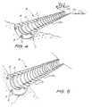
- Figure 4. depicts a plurality of adjoining tyre sectors of Figure 1. forming a drainage channel.
- Figure 5 depicts a plurality of adjoining tyre sectors according to Figure 2, forming a drainage channel.
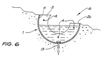
- Figure 6. depicts a cross section of a drainage channel according to the invention.
- an open semi-circular trench 1 is dug by hand or by mechanical means, having a diameter corresponding at least approximately to the outside diameter of the tyre sectors 2.
- the trench may have a sand bed, or may be lined with plastic on its inner surface to prevent vegetation from growing up and displacing the tyre sectors 2.
- the tyre sectors 2 are then placed in the trench 1 side by side with side walls 3 abutting.
- the elongate joining members 4 are inserted through apertures 5 in each of the side walls 3 of the tyre sectors 2 and thereby extend generally parallel to the trench 1, on either side of, and along the channel 6 itself.
- clamping means 7 such as a washer 8 and nut 9 which engage a threaded portion of each end 10 of the members 4.
- the clamping means 7 allow longitudinal adjustment of the elongate members 4.
- the washer 8 is also provided with an aperture and the combination of washer 8 and nut 9 are not able to pass through the apertures 5 in the side walls 3 of the tyre sectors 2.
- the joining members 4 may be longitudinally adjusted so that the tyre sectors 2 can be drawn together between the washers 8 to prevent separation of adjoining tyre sectors 2 and thereby form a seal therebetween.
- the tread walls 11 of the tyre sectors 2 may have a hole 12 adapted to receive a peg 13, to stably locate the tyre sectors 2 in the ground, and prevent twisting or travel thereof.
- the peg 13 will have an enlarged head section which is not able to pass through the hole 12.
- the tyre sectors 2 may have differing circumferential portions to provide varying depths of channel 6 to suit the terrain for example flat or inclined, depending on whether the drain is intended to extend down or across the incline.
- the sector 2a depicted in Figure 1 is suitable for flat terrain or extending down hill.
- the heights of the opposing side walls 3 of the tyre sectors 2 may vary relative to each other, as shown in the tyre sector 2b in Figure 2, which are suitable for a drain extending across the incline.
- the sector 2c shown in Figure 3 provides a shallower drain.
- the drainage construction according to the invention possesses several advantages over existing structures in reducing drainage maintenance and reducing conventional formal drainage costs. It also saves natural resources such as sand and cement, recycles a waste product which is creating environmental damage and increases the life of existing and future landfill sites.
- the drainage structure is economical in that it: reduces the machinery and labour required to maintain open drains, etc, reduces expensive drainage requirements downstream, reduces/or eliminates the need for sedimentation traps, reduces dredging costs, and increases staff available for the purpose of maintaining more valuable assets.
Landscapes
- Engineering & Computer Science (AREA)
- Structural Engineering (AREA)
- General Engineering & Computer Science (AREA)
- Civil Engineering (AREA)
- Agronomy & Crop Science (AREA)
- Mechanical Engineering (AREA)
- Life Sciences & Earth Sciences (AREA)
- Architecture (AREA)
- Tires In General (AREA)
- Road Paving Structures (AREA)
- Cyclones (AREA)
- Treatment Of Water By Ion Exchange (AREA)
- Treatment Of Sludge (AREA)
- Sink And Installation For Waste Water (AREA)
- Revetment (AREA)
Claims (9)
- Drainageanlage, umfassend:
eine Vielzahl von Elementen, die durch Verbindungsmittel (4) verbunden sind, um einen länglichen Kanal (6) zu bilden, gekennzeichnet dadurch, daß jedes der Elemente einen Bogensektor (2) eines Altreifens umfaßt, bei dem die Seitenwand jedes Reifensektors mit der Seitenwand des nächsten benachbarten Reifensektors aneinanderstößt, wobei der Kanal durch die inneren runden Querschnittsflächen der aufeinanderfolgenden benachbarten Reifenwandsektoren definiert wird. - Drainageanlage gemäß Anspruch 1, bei der jeder Reifensektor (2) 1/3 bis 1/2 eines Reifenumfanges umfaßt.
- Drainageanlage gemäß Anspruch 2, bei der die untere Auflagefläche (11) eines oder mehrerer Reifen einer Vielzahl von verbundenen Reifenteilen mit einer oder mehreren Bohrungen (12) versehen ist, die zum Hindurchtreiben eines oder mehrerer Befestigungspflöcke (13) angepaßt ist.
- Drainageanlage gemäß Anspruch 2, bei der das Verbindungsmittel (4) ein oder mehrere längliche Verbindungselemente umfaßt, die angepaßt sind, um die Seitenwände aufeinanderfolgender einzelner Reifensektoren unter Zugpannung oder auf andere Art und Weise in Nebeneinanderstellung zu bringen.
- Drainageanlage gemäß Anspruch 4, bei der das Verbindungsmittel (4) ein Paar von im wesentlichen parallelen Stangen oder Drahtseilen umfaßt, die durch Öffnungen (5) in den Seitenwänden der Reifensektoren führen und an beiden Enden der Anlage festgespannt sind.
- Drainageanlage gemäß Anspruch 5, die außerdem eine dritte Stange oder ein drittes Drahtseil umfaßt, die/das zu dem ersten Paar von Stangen oder Drahtseilen parallel ist, wobei die dritte Stange oder das dritte Drahtseil auch durch Öffnungen in den Seitenwänden der Reifensektoren hindurchführen und an beiden Enden der Anlage festgespannt ist.
- Drainageanlage gemäß Anspruch 5 oder 6, bei der die Stangen oder Drahtseile aus biegsamen Stahlseilen oder synthetischen oder natürlichen Seilen oder Stangen ausgewählt werden.
- Drainageanlage gemäß Anspruch 5, die durch Spannmittel festgespannt wird, die angepaßt sind, um eine Einstellung der Zugpannung in den Stangen oder Drahtseilen zu erlauben, um die Reifensektorenseitenwände elastisch zusammenzudrücken.
- Drainageanlage gemäß Anspruch 5, bei der aufeinanderfolgende Reifensektoren durch ein oder mehrere Klebstoffe oder Schrauben oder Krampen verbunden sind.
Applications Claiming Priority (3)
| Application Number | Priority Date | Filing Date | Title |
|---|---|---|---|
| AU9147/90 | 1990-03-15 | ||
| AUPJ914790 | 1990-03-15 | ||
| PCT/AU1991/000082 WO1991014049A1 (en) | 1990-03-15 | 1991-03-08 | Drainage and erosion reduction means |
Publications (3)
| Publication Number | Publication Date |
|---|---|
| EP0519994A1 EP0519994A1 (de) | 1992-12-30 |
| EP0519994A4 EP0519994A4 (en) | 1993-02-10 |
| EP0519994B1 true EP0519994B1 (de) | 1995-06-07 |
Family
ID=3774555
Family Applications (1)
| Application Number | Title | Priority Date | Filing Date |
|---|---|---|---|
| EP19910906291 Expired - Lifetime EP0519994B1 (de) | 1990-03-15 | 1991-03-08 | Drainage- und erosionsverminderungssystem |
Country Status (8)
| Country | Link |
|---|---|
| US (1) | US5366323A (de) |
| EP (1) | EP0519994B1 (de) |
| AT (1) | ATE123544T1 (de) |
| AU (1) | AU630285B2 (de) |
| CA (1) | CA2078237A1 (de) |
| DE (1) | DE69110278T2 (de) |
| ES (1) | ES2074713T3 (de) |
| WO (1) | WO1991014049A1 (de) |
Families Citing this family (11)
| Publication number | Priority date | Publication date | Assignee | Title |
|---|---|---|---|---|
| US5823711A (en) * | 1995-11-01 | 1998-10-20 | Environmental Golf System U.S.A., Inc. | Water drainage and collection system and method of construction thereof |
| FR2795105B1 (fr) * | 1999-06-18 | 2001-09-07 | Sacer | Dispositif enterre de drainage et d'assainissement des chaussees et procede de realisation |
| US6227763B1 (en) | 1999-06-29 | 2001-05-08 | Philip A. Kuhns | Waterway |
| US7306402B2 (en) * | 2002-09-05 | 2007-12-11 | Graber Loren R | Landscaping channel liner apparatus |
| US7744315B2 (en) * | 2004-02-05 | 2010-06-29 | Baro Construction Key-Technology Co., Ltd. | Reinforcement of foundation |
| US20120315089A1 (en) * | 2011-06-08 | 2012-12-13 | Richard Burns | System for reducing storm run-off erosion and related method |
| US8920071B2 (en) * | 2011-09-07 | 2014-12-30 | Hazard Mitigation, Inc. | Apparatus and method for limiting ice formation |
| FR3057584B1 (fr) * | 2016-10-14 | 2018-10-19 | Ecoplage | Dispositif de fixation d'une canalisation souple dans le sol, en particulier dans un sol mouvant tel que du sable |
| RU2699192C1 (ru) * | 2018-12-11 | 2019-09-03 | Федеральное государственное бюджетное научное учреждение "Всероссийский научно-исследовательский институт гидротехники и мелиорации имени А.Н. Костякова" (ФГБНУ "ВНИИГиМ им. А.Н. Костякова") | Дренажный канал для транспортирования дренажного стока |
| US11155971B2 (en) * | 2019-06-12 | 2021-10-26 | Dakota Tate | System and method for constructing a culvert using vehicle tires |
| RU206608U1 (ru) * | 2021-03-01 | 2021-09-17 | Федеральное государственное казенное военное образовательное учреждение высшего образования "ВОЕННАЯ АКАДЕМИЯ МАТЕРИАЛЬНО-ТЕХНИЧЕСКОГО ОБЕСПЕЧЕНИЯ имени генерала армии А.В. Хрулева" Министерства обороны Российской Федерации | Временная водопропускная труба малого диаметра под дорожной насыпью из автомобильных шин в металлическом каркасе |
Family Cites Families (16)
| Publication number | Priority date | Publication date | Assignee | Title |
|---|---|---|---|---|
| US954283A (en) * | 1908-01-17 | 1910-04-05 | Frederick W Hawkes | Revetment. |
| US1515709A (en) * | 1922-05-23 | 1924-11-18 | Augustus H Stowell | Irrigation ditch |
| FR1359219A (fr) * | 1963-03-11 | 1964-04-24 | Tuyaux En Beton Et De Materiau | Caniveau pour talus, formé d'éléments en béton ou autres matériaux convenables |
| US3764446A (en) * | 1972-01-19 | 1973-10-09 | M Martin | Discarded tire carcasses secured together by fasteners to form a chain or mat |
| DE2619129C2 (de) * | 1976-04-30 | 1982-04-15 | Ziegelwerke Heinrich Oltmanns, 2905 Edewecht | Aus einem extrudierten Schlauch hergestelltes gewelltes Rohr aus thermoplastischem Kunststoffmaterial |
| US3848853A (en) * | 1973-03-15 | 1974-11-19 | M Way | Highway safety tire device |
| US3951384A (en) * | 1975-03-20 | 1976-04-20 | Hildreth Jr Robert E | Impact absorbing device |
| DE2604500C3 (de) * | 1976-02-05 | 1981-05-27 | Rainer Isolierrohrfabrik Max Drossbach, 8852 Rain | Dränrohr aus Kunststoff |
| US4022434A (en) * | 1976-02-09 | 1977-05-10 | Moore Phil D | Tire fence |
| AT345192B (de) * | 1977-03-17 | 1978-09-11 | Pelz Franz | Rohr |
| JPS5636984Y2 (de) * | 1977-03-18 | 1981-08-31 | ||
| FR2625757B1 (fr) * | 1988-01-13 | 1990-06-15 | Manent Vincent | Element prefabrique pour la realisation de caniveaux d'ecoulement des eaux |
| FR2626301B1 (fr) * | 1988-01-26 | 1991-07-12 | Denis Combes | Caniveaux-bacs suspendus pour descentes d'eau |
| US4824287A (en) * | 1988-02-19 | 1989-04-25 | Tracy Lawrence M | Septic system |
| US5011327A (en) * | 1990-06-15 | 1991-04-30 | Thiac E Brandt | Erosion barrier |
| US5236756A (en) * | 1992-04-22 | 1993-08-17 | Halliburton Danny B | Drainage culverts made of sidewalls from discarded tires |
-
1991
- 1991-03-08 AT AT91906291T patent/ATE123544T1/de not_active IP Right Cessation
- 1991-03-08 EP EP19910906291 patent/EP0519994B1/de not_active Expired - Lifetime
- 1991-03-08 US US07/930,420 patent/US5366323A/en not_active Expired - Fee Related
- 1991-03-08 DE DE69110278T patent/DE69110278T2/de not_active Expired - Fee Related
- 1991-03-08 CA CA 2078237 patent/CA2078237A1/en not_active Abandoned
- 1991-03-08 ES ES91906291T patent/ES2074713T3/es not_active Expired - Lifetime
- 1991-03-08 WO PCT/AU1991/000082 patent/WO1991014049A1/en not_active Ceased
- 1991-03-14 AU AU73566/91A patent/AU630285B2/en not_active Ceased
Also Published As
| Publication number | Publication date |
|---|---|
| ES2074713T3 (es) | 1995-09-16 |
| DE69110278D1 (de) | 1995-07-13 |
| EP0519994A4 (en) | 1993-02-10 |
| ATE123544T1 (de) | 1995-06-15 |
| CA2078237A1 (en) | 1991-09-16 |
| US5366323A (en) | 1994-11-22 |
| DE69110278T2 (de) | 1996-01-04 |
| AU7356691A (en) | 1991-09-19 |
| WO1991014049A1 (en) | 1991-09-19 |
| AU630285B2 (en) | 1992-10-22 |
| EP0519994A1 (de) | 1992-12-30 |
Similar Documents
| Publication | Publication Date | Title |
|---|---|---|
| US5366323A (en) | Drainage and erosion reduction means | |
| US7950878B2 (en) | Shoreline erosion control system | |
| AU2003252903A1 (en) | Reinforcing system for stackable retaining wall units | |
| US7828499B2 (en) | Erosion control system | |
| US4946308A (en) | Erosion-control matting and method for making same | |
| US20110100493A1 (en) | Drainage system having an end cap for diverting fluid | |
| HUP0003696A2 (hu) | Eljárás és berendezés gumiabroncsok feldolgozásához | |
| KR102571807B1 (ko) | 관매설용 토류 프레임 | |
| KR101230275B1 (ko) | 토목 시공용 튜브 구조물 | |
| RU2068914C1 (ru) | Дренажное устройство | |
| KR20100124165A (ko) | 항타 피에이치씨 파일용 슈우 | |
| RU173982U1 (ru) | Устройство для укрепления земляного полотна и склонов | |
| CN114396051B (zh) | 一种基坑边坡开挖及支护结构的施工方法 | |
| KR20010084709A (ko) | 폐타이어 트레드를 이용한 지반보강 공법 | |
| Miyata et al. | A case study of damages of geogrid reinforced soil walls triggered by rainfall | |
| KR20150109121A (ko) | 폐타이를 결합한 기성제 콘크리트파일 및 이를 이용한 사면안정화 구조 | |
| JPH05505005A (ja) | 排水と浸食減少手段 | |
| KR100566668B1 (ko) | 도로 사면용 슬라이딩 보강구조 | |
| US20170211239A1 (en) | Vehicle tracking control systems and methods | |
| CN112267478A (zh) | 增强加固与排水的膨胀土快速修复方法 | |
| KR100218901B1 (ko) | 폐타이어를 이용한 배수 및 폐기물 매립방법 | |
| CN113073546A (zh) | 高速公路工程的桥梁引道防滑安全结构及其施工方法 | |
| KR100629152B1 (ko) | 침식지에서의 유출토사 차단방법 및 그 장치 | |
| EP0647740B1 (de) | Verfahren und Vorrichtung zur Herstellung verkleideter Gräben im Boden sowie verkleidete Gräben | |
| AU2010227078B2 (en) | A Pipe and Culvert Fabrication |
Legal Events
| Date | Code | Title | Description |
|---|---|---|---|
| PUAI | Public reference made under article 153(3) epc to a published international application that has entered the european phase |
Free format text: ORIGINAL CODE: 0009012 |
|
| 17P | Request for examination filed |
Effective date: 19920922 |
|
| AK | Designated contracting states |
Kind code of ref document: A1 Designated state(s): AT BE CH DE DK ES FR GB GR IT LI LU NL SE |
|
| A4 | Supplementary search report drawn up and despatched |
Effective date: 19921221 |
|
| AK | Designated contracting states |
Kind code of ref document: A4 Designated state(s): AT BE CH DE DK ES FR GB GR IT LI LU NL SE |
|
| RAP1 | Party data changed (applicant data changed or rights of an application transferred) |
Owner name: WHITEHEAD, GRAHAM LEE Owner name: NICHOLSON, IAN CRAIG |
|
| RIN1 | Information on inventor provided before grant (corrected) |
Inventor name: NICHOLSON, IAN CRAIG |
|
| 17Q | First examination report despatched |
Effective date: 19940526 |
|
| GRAA | (expected) grant |
Free format text: ORIGINAL CODE: 0009210 |
|
| AK | Designated contracting states |
Kind code of ref document: B1 Designated state(s): AT BE CH DE DK ES FR GB GR IT LI LU NL SE |
|
| PG25 | Lapsed in a contracting state [announced via postgrant information from national office to epo] |
Ref country code: NL Effective date: 19950607 Ref country code: LI Effective date: 19950607 Ref country code: GR Free format text: LAPSE BECAUSE OF FAILURE TO SUBMIT A TRANSLATION OF THE DESCRIPTION OR TO PAY THE FEE WITHIN THE PRESCRIBED TIME-LIMIT Effective date: 19950607 Ref country code: FR Effective date: 19950607 Ref country code: DK Effective date: 19950607 Ref country code: CH Effective date: 19950607 Ref country code: BE Effective date: 19950607 Ref country code: AT Effective date: 19950607 |
|
| REF | Corresponds to: |
Ref document number: 123544 Country of ref document: AT Date of ref document: 19950615 Kind code of ref document: T |
|
| ITF | It: translation for a ep patent filed | ||
| REF | Corresponds to: |
Ref document number: 69110278 Country of ref document: DE Date of ref document: 19950713 |
|
| PG25 | Lapsed in a contracting state [announced via postgrant information from national office to epo] |
Ref country code: SE Effective date: 19950907 |
|
| REG | Reference to a national code |
Ref country code: CH Ref legal event code: PL |
|
| REG | Reference to a national code |
Ref country code: ES Ref legal event code: FG2A Ref document number: 2074713 Country of ref document: ES Kind code of ref document: T3 |
|
| NLV1 | Nl: lapsed or annulled due to failure to fulfill the requirements of art. 29p and 29m of the patents act | ||
| EN | Fr: translation not filed | ||
| PG25 | Lapsed in a contracting state [announced via postgrant information from national office to epo] |
Ref country code: GB Effective date: 19960308 |
|
| PG25 | Lapsed in a contracting state [announced via postgrant information from national office to epo] |
Ref country code: LU Free format text: LAPSE BECAUSE OF NON-PAYMENT OF DUE FEES Effective date: 19960331 |
|
| PLBE | No opposition filed within time limit |
Free format text: ORIGINAL CODE: 0009261 |
|
| STAA | Information on the status of an ep patent application or granted ep patent |
Free format text: STATUS: NO OPPOSITION FILED WITHIN TIME LIMIT |
|
| 26N | No opposition filed | ||
| GBPC | Gb: european patent ceased through non-payment of renewal fee |
Effective date: 19960308 |
|
| PGFP | Annual fee paid to national office [announced via postgrant information from national office to epo] |
Ref country code: DE Payment date: 19991231 Year of fee payment: 10 |
|
| PG25 | Lapsed in a contracting state [announced via postgrant information from national office to epo] |
Ref country code: DE Free format text: LAPSE BECAUSE OF NON-PAYMENT OF DUE FEES Effective date: 20020101 |
|
| PGFP | Annual fee paid to national office [announced via postgrant information from national office to epo] |
Ref country code: ES Payment date: 20020315 Year of fee payment: 12 |
|
| PG25 | Lapsed in a contracting state [announced via postgrant information from national office to epo] |
Ref country code: ES Free format text: LAPSE BECAUSE OF NON-PAYMENT OF DUE FEES Effective date: 20030310 |
|
| REG | Reference to a national code |
Ref country code: ES Ref legal event code: FD2A Effective date: 20030310 |
|
| PG25 | Lapsed in a contracting state [announced via postgrant information from national office to epo] |
Ref country code: IT Free format text: LAPSE BECAUSE OF NON-PAYMENT OF DUE FEES;WARNING: LAPSES OF ITALIAN PATENTS WITH EFFECTIVE DATE BEFORE 2007 MAY HAVE OCCURRED AT ANY TIME BEFORE 2007. THE CORRECT EFFECTIVE DATE MAY BE DIFFERENT FROM THE ONE RECORDED. Effective date: 20050308 |