EP0520114A1 - Unterbrechbarer Spülmechanismus mit gesicherter Minimalspülung - Google Patents
Unterbrechbarer Spülmechanismus mit gesicherter Minimalspülung Download PDFInfo
- Publication number
- EP0520114A1 EP0520114A1 EP91430017A EP91430017A EP0520114A1 EP 0520114 A1 EP0520114 A1 EP 0520114A1 EP 91430017 A EP91430017 A EP 91430017A EP 91430017 A EP91430017 A EP 91430017A EP 0520114 A1 EP0520114 A1 EP 0520114A1
- Authority
- EP
- European Patent Office
- Prior art keywords
- interruptible
- push button
- flushing mechanism
- valve
- mechanism according
- Prior art date
- Legal status (The legal status is an assumption and is not a legal conclusion. Google has not performed a legal analysis and makes no representation as to the accuracy of the status listed.)
- Granted
Links
Images


Classifications
-
- E—FIXED CONSTRUCTIONS
- E03—WATER SUPPLY; SEWERAGE
- E03D—WATER-CLOSETS OR URINALS WITH FLUSHING DEVICES; FLUSHING VALVES THEREFOR
- E03D1/00—Water flushing devices with cisterns ; Setting up a range of flushing devices or water-closets; Combinations of several flushing devices
- E03D1/02—High-level flushing systems
- E03D1/14—Cisterns discharging variable quantities of water also cisterns with bell siphons in combination with flushing valves
- E03D1/142—Cisterns discharging variable quantities of water also cisterns with bell siphons in combination with flushing valves in cisterns with flushing valves
-
- E—FIXED CONSTRUCTIONS
- E03—WATER SUPPLY; SEWERAGE
- E03D—WATER-CLOSETS OR URINALS WITH FLUSHING DEVICES; FLUSHING VALVES THEREFOR
- E03D1/00—Water flushing devices with cisterns ; Setting up a range of flushing devices or water-closets; Combinations of several flushing devices
- E03D1/02—High-level flushing systems
- E03D1/14—Cisterns discharging variable quantities of water also cisterns with bell siphons in combination with flushing valves
- E03D2001/147—Cisterns discharging variable quantities of water also cisterns with bell siphons in combination with flushing valves having provisions for active interruption of flushing
-
- E—FIXED CONSTRUCTIONS
- E03—WATER SUPPLY; SEWERAGE
- E03D—WATER-CLOSETS OR URINALS WITH FLUSHING DEVICES; FLUSHING VALVES THEREFOR
- E03D1/00—Water flushing devices with cisterns ; Setting up a range of flushing devices or water-closets; Combinations of several flushing devices
- E03D1/02—High-level flushing systems
- E03D1/14—Cisterns discharging variable quantities of water also cisterns with bell siphons in combination with flushing valves
- E03D2001/147—Cisterns discharging variable quantities of water also cisterns with bell siphons in combination with flushing valves having provisions for active interruption of flushing
- E03D2001/148—Cisterns discharging variable quantities of water also cisterns with bell siphons in combination with flushing valves having provisions for active interruption of flushing with means to prevent premature closing of flushing valve
Definitions
- the present invention relates to a "interruptable" flushing mechanism, with minimum guaranteed flow, for a toilet flush tank, the "interruptable” neologism meaning: whose action can be interrupted.
- Hunting mechanisms are known (EP-A-0.124.458, EP-A-0.128.847, FR-A-2.591.250, FR-A-2.580.694) comprising a valve movable in axial translation and intended for s '' apply to the edge of the drain orifice provided in the bottom of the flush tank, this valve being mounted at the end or at the bottom of a tubular rod itself secured to a float the function is to keep said valve away from its seat, during the water evacuation or flushing process; these flushing mechanisms further comprising a push button control device and a system for transmitting or lifting the valve actuated by said push button.
- a device for actuating the flow valve comprising a push-button for control integral with a thrust member that can slide axially and connected, by means of a hinge, to a thrust head that can pivot laterally in a limited manner, on either side of its sliding axis, so as to act on one or the other of the two arms of a tilting lever, one of the arms of this lever being attached, by means of remote transmission members, to the flow valve, so that according to the pivoting push head presses on one or the other of the arms of the pivoting lever, an upward pulling action is exerted causing the raising of said valve or a downward pushing action causing the lowering of the latter in the direction of his seat.
- This device has the particular disadvantage of not transmitting axial forces to the tube equipped with the flow valve, so that the longitudinal translation of the tube-flow valve assembly is not perfect, which, of on the one hand, increases the importance of the forces necessary for the displacement of said assembly, especially in the upward direction and, on the other hand, can lead, in the long run, to a misalignment of the movable element of the flushing mechanism and a poor application the valve on its seat promoting the appearance of a leak.
- Another major drawback of this device is that it makes it possible to interrupt the flushing process at any time after having started it, so that the flow of water can be stopped before the bowl is completely cleaned, and that ineffective quantities of water evacuated are wasted, the use of such a device does not, moreover, offer the guarantees of desirable cleanliness and hygiene.
- An object of the present invention is therefore to remedy the aforementioned drawbacks and, more particularly, the shortcoming indicated last.
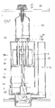
- this object is achieved thanks to a flushing mechanism comprising a lift chamber arranged in the upper part of said mechanism and in which is housed the float secured in axial translation to the shutter valve of the drain orifice, this lift chamber being supplemented by rapid emptying means comprising at least one member subject to the push button and at least one orifice placed in the bottom or near the bottom of said chamber, these means being placed in the operative position during pressing the push button, and inoperative position when you stop pressing it.
- the base 5 has a central orifice C whose upper circular edge 8 constitutes the seat of the valve 3.
- the base 5 When the flushing mechanism is positioned inside a flushing tank itself fixed on a toilet bowl, the base 5 is fixedly installed, by means of a nut (not shown) screwed onto the threaded lower cylindrical portion 5a of said base, in the orifice 6.
- the central orifice C of the base 5 constitutes the emptying orifice of said tank.
- the seal between the bottom 7 of the reservoir and the seat or bearing face of the base 5 is produced by means of an intermediate annular seal 9 made of rubber or other suitable material.
- the base of the outer envelope 1 and the base 5 are arranged in a complementary manner or provided with complementary joining means allowing them to be rigidly assembled, in a separable manner, while allowing the passage of water between said base and said base.
- the base 5 is, for example, provided with three locking forks 10 spaced 120 degrees and between the branches of which can be engaged and retained the base of the casing 1. Between the locking forks are thus formed large openings 11 , for the passage of water.
- the upper part of the envelope 1 is arranged so as to constitute an auxiliary tank 12.
- the upper part 1a of the envelope 1 constitutes the side wall of this tank, the bottom of which is formed, according to the embodiment illustrated in FIGS. 1 to 4, by a circular wall or partition 13.
- the side wall 1a of the tank 12 is provided with discharge orifices 14 distributed over the periphery of said wall, these orifices being placed above said bottom according to the embodiment illustrated in FIGS. 1 to 6.
- the orifices 14 are disposed approximately in the middle part of the height of the casing 1 and of the flushing mechanism, and at a level which is very clearly below the level where the orifice above the overflow tube is placed. 4, for example about halfway up the latter.
- the float 2 of the flushing mechanism is housed inside the lift chamber 12.
- This float is advantageously constituted by a bell open at its base and closed at its top and this bell is rigidly secured to a spacer tube 15 by means of which it is connected to the valve 3.
- the latter is, for example, constituted by a seal in the form of a circular crown, made of rubber or other similar material, and it is installed in a peripheral groove which has a rigid frame 16 constituting the lower end of the spacer tube 15.
- the mechanism according to the invention further comprises means allowing rapid emptying of the lift chamber 12.
- these means comprise, in addition to the orifices 14 previously described, a shutter constituted by the cylindrical side wall 26 of an auxiliary tank 25 of annular shape, disposed, with an axial displacement capacity, around the spacer tube 15.
- This auxiliary tank 25 is open at its upper part and, its side wall 26 comprises, near from the bottom 25a of said tank orifices 27 whose shape, number and distribution correspond to the shape, number and distribution of the orifices 14, opposite which they can be placed.
- the side wall 2a of the float 2 is housed in the annular auxiliary tank 25, the height of this wall being substantially equal to the height of the internal cylindrical wall 25b of said tank.
- the external side wall 26 of the annular auxiliary tank 25 has a height substantially greater than that of the internal wall 25b of said tank.
- the spacer tube 15 comprises a tubular extension 15a, the upper orifice D of which is placed substantially at the level where the orifice A of the overflow tube 4 is located, when the device is at rest, and preferably slightly at below this level.
- the side wall 26 of the auxiliary tank 25 is rigidly secured to two columns or connecting rods 28 oriented upwards and diametrically opposite.
- Springs 30 acting in compression are arranged around the upper part of the rods 28. These springs are wedged, on the one hand, against the underside of the bar 29 and, on the other hand, against a circular shoulder 1c of the outer casing 1.
- the transmission rod 22 is provided with a thrust member making it possible to lower the assembly: shutter 26-auxiliary reservoir 25, when the push-button 17 is pressed.
- This thrust member is, for example, constituted by a ring 31 wedged on the rod 22 and disposed above the bar 29, and, preferably, in contact with the latter.
- the overflow tube 4 of the flushing mechanism is disposed outside of the casing 1. Its lower orifice B is connected to the base 5 by a conduit 32 opening into said base, below the seat 8 of the valve 3.
- the level N of the water contained in the tank is generally a little below the location where the upper ends of the overflow tube 4 and the tubular extension 15a of the spacer tube 15 are located, so that said overflow tube can fulfill its function in the event of a faulty closing of the supply valve.
- Water also fills the lift chamber 12 and the auxiliary tank 25, housed therein.
- the moving part 2-15-3 remains in the raised position as long as the buoyancy of the float remains ensured.
- the level of the water contained in the flushing tank decreases gradually and rapidly, while the level of the water contained in the lift chamber 12 and more precisely in the auxiliary tank 25 also drops but much more slowly due to the fact that the orifices 27 formed near the bottom of the latter are closed in leaktight manner by the cylindrical obturating wall 26.
- the movable assembly 2-15-3 naturally falls back into its position rest and shutter of the drain orifice C ( Figure 1) when there is no more water in the auxiliary tank 25 and the lift of the float 2 is no longer ensured.
- the embodiment of the flushing mechanism illustrated in Figure 7 differs from that previously described, mainly by the fact that the lift chamber 12 does not contain an auxiliary tank and that the shutter 26 allowing to place orifices 14 or not provided in the side wall of the envelope 1, in relation to said chamber, is constituted by the movable bottom of the latter.
- the mobile shutter 26 consists of a circular plate disposed around the spacer tube 15 and capable of sliding, in a non-leaktight manner, along the latter and the internal surface of the envelope 1.
- This plate 26 constituting the movable bottom of the chamber lift 12, is connected, by means of two vertical and parallel rods or columns 28, to a drive bar 29.
- Springs 30 tend to keep the assembly 26-28-29 in the high position, as indicated previously.
- the flushing mechanism produced according to this embodiment also makes it possible to interrupt the emptying process by pressing the push button 17 a second time, but this interruption cannot take place as long as the falling level of the water does not has not reached holes 14.
Landscapes
- Health & Medical Sciences (AREA)
- Life Sciences & Earth Sciences (AREA)
- Engineering & Computer Science (AREA)
- Hydrology & Water Resources (AREA)
- Public Health (AREA)
- Water Supply & Treatment (AREA)
- Sanitary Device For Flush Toilet (AREA)
Priority Applications (2)
| Application Number | Priority Date | Filing Date | Title |
|---|---|---|---|
| DE69114836T DE69114836D1 (de) | 1991-06-25 | 1991-06-25 | Unterbrechbarer Spülmechanismus mit gesicherter Minimalspülung. |
| AT91430017T ATE130651T1 (de) | 1991-06-25 | 1991-06-25 | Unterbrechbarer spülmechanismus mit gesicherter minimalspülung. |
Applications Claiming Priority (3)
| Application Number | Priority Date | Filing Date | Title |
|---|---|---|---|
| FR9006414A FR2662194B1 (fr) | 1990-05-17 | 1990-05-17 | Mecanisme de chasse interrompable, a ecoulement minimal assure. |
| AU81232/91A AU641259B2 (en) | 1990-05-17 | 1991-07-23 | Stoppable flushing mechanism with assured minimal flow |
| US08/111,432 US5305474A (en) | 1990-05-17 | 1993-08-25 | Stoppable flushing mechanism with assured minimal flow |
Publications (2)
| Publication Number | Publication Date |
|---|---|
| EP0520114A1 true EP0520114A1 (de) | 1992-12-30 |
| EP0520114B1 EP0520114B1 (de) | 1995-11-22 |
Family
ID=27156420
Family Applications (1)
| Application Number | Title | Priority Date | Filing Date |
|---|---|---|---|
| EP91430017A Expired - Lifetime EP0520114B1 (de) | 1990-05-17 | 1991-06-25 | Unterbrechbarer Spülmechanismus mit gesicherter Minimalspülung |
Country Status (4)
| Country | Link |
|---|---|
| US (1) | US5305474A (de) |
| EP (1) | EP0520114B1 (de) |
| AU (1) | AU641259B2 (de) |
| FR (1) | FR2662194B1 (de) |
Cited By (2)
| Publication number | Priority date | Publication date | Assignee | Title |
|---|---|---|---|---|
| ES2073985A2 (es) * | 1993-02-24 | 1995-08-16 | Martinez Juan Vidal | Sistema dosificador de agua para cisternas de inodoros. |
| ES2137810A1 (es) * | 1993-12-17 | 1999-12-16 | Idrols Sa | Primer certificado de adicion a la patente principal n- 9302624 por descargador para cisternas con interrupcion de desacarga. |
Families Citing this family (19)
| Publication number | Priority date | Publication date | Assignee | Title |
|---|---|---|---|---|
| DE4122394A1 (de) * | 1991-07-05 | 1993-01-07 | Heinrich Menge | Spuelvorrichtung |
| FR2680192B1 (fr) | 1991-08-09 | 1993-10-15 | Matieres Plastiques Ste Phoceenn | Mecanisme de chasse a double commande, permettant d'operer, selectivement, la vidange complete ou partielle du reservoir. |
| DE9311189U1 (de) * | 1992-09-21 | 1993-09-09 | Geberit Ag, Jona, St.Gallen | Ablaufventil für einen Spülkasten |
| DE29503497U1 (de) * | 1994-05-16 | 1995-04-20 | Geberit Technik AG, Jona, St.Gallen | Spülvorrichtung für ein Wasserklosett |
| DE29517363U1 (de) * | 1995-01-16 | 1995-12-21 | Geberit Technik AG, Jona, St.Gallen | Spüleinrichtung in einem WC-Spülkasten |
| US5956781A (en) * | 1996-02-20 | 1999-09-28 | James Hardie Research Pty Limited | Dual flush cistern |
| DE29702564U1 (de) * | 1997-02-14 | 1997-04-03 | Schneider, Helmhold, Dr., 57610 Altenkirchen | Ablaufvorrichtung an einem WC-Spülkasten mit wahlweiser Voll- oder Teilspülung |
| DE19748621A1 (de) * | 1997-11-04 | 1999-05-06 | Dal Georg Rost & Soehne Sanita | Ablaufventil für Spülkästen |
| SE515154C2 (sv) * | 1998-08-26 | 2001-06-18 | Ninotech Hb | Sätt och anordning för tidsstyrd spolning vid spoltoaletter |
| US6081938A (en) * | 1998-09-14 | 2000-07-04 | Fluidmaster, Inc. | Dual-flush valve |
| RU2250310C2 (ru) * | 2003-03-25 | 2005-04-20 | Ооо "Инкоэр" | Сливная арматура |
| RU2283928C1 (ru) * | 2004-12-30 | 2006-09-20 | Ооо "Инкоэр" | Сливная арматура |
| US7634821B2 (en) * | 2005-11-07 | 2009-12-22 | Kohler Co. | Canister flush valve |
| EP1870527B1 (de) * | 2006-06-20 | 2017-05-31 | Geberit International AG | Vorrichtung zur Betätigung des Ablaufventils eines Sanitärartikels |
| DE102006051823A1 (de) | 2006-11-03 | 2008-05-08 | Tece Gmbh | Zwei-Mengen-Ablaufventil |
| ATE483073T1 (de) * | 2007-05-25 | 2010-10-15 | Geberit Int Ag | Betätigungsvorrichtung für eine auslaufgarnitur und auslaufgarnitur mit einer solchen betätigungsvorrichtung sowie verfahren zum montieren einer solchen auslaufgarnitur |
| US8806669B2 (en) * | 2008-04-10 | 2014-08-19 | Kohler Co. | Toilet flush valve with reducing cross section valve seat |
| ES2605422T3 (es) * | 2012-08-03 | 2017-03-14 | Geberit International Ag | Grifería de descarga regulable en la altura |
| ES2570974T3 (es) * | 2013-10-28 | 2016-05-23 | Geberit Int Ag | Adaptador de desagüe para una cisterna de lavado |
Citations (4)
| Publication number | Priority date | Publication date | Assignee | Title |
|---|---|---|---|---|
| DE639760C (de) * | 1935-04-12 | 1936-12-12 | Albert Gebert Jun | Abtrittspuelkasten mit Ventilverschluss |
| FR1455293A (fr) * | 1965-08-11 | 1966-04-01 | W J Stokvis Konink Fabriek Van | Réservoir de chasse avec clapet de fond |
| FR2591250A1 (fr) * | 1985-03-19 | 1987-06-12 | Spmp Sa | Dispositif de chasse a commande par bouton-poussoir pour reservoir de chasse d'eau |
| FR2621630A1 (fr) * | 1987-10-09 | 1989-04-14 | Pocachard Thierry | Mecanisme de commande de chasse d'eau pour wc par poussoir |
Family Cites Families (5)
| Publication number | Priority date | Publication date | Assignee | Title |
|---|---|---|---|---|
| AU1238870A (en) * | 1970-03-10 | 1971-09-16 | Better Packages, Inc | Pressure sensitive adhesive tape dispenser |
| US3987752A (en) * | 1975-05-05 | 1976-10-26 | Owens-Corning Fiberglas Corporation | Apparatus for dispensing elongate flexible material |
| CH643622A5 (de) * | 1979-12-18 | 1984-06-15 | Geberit Ag | Ablaufgarnitur fuer spuelkasten. |
| EP0103045B1 (de) * | 1982-09-15 | 1985-12-27 | Georg Rost & Söhne Armaturenfabrik GmbH & CO. KG | Spülkasten-Ablaufventil |
| FR2621378B1 (fr) * | 1987-10-05 | 1989-12-15 | Siamp Cedap Reunies | Dispositif d'actionnement a bascule de la soupape de vidange d'un reservoir de chasse |
-
1990
- 1990-05-17 FR FR9006414A patent/FR2662194B1/fr not_active Expired - Lifetime
-
1991
- 1991-06-25 EP EP91430017A patent/EP0520114B1/de not_active Expired - Lifetime
- 1991-07-23 AU AU81232/91A patent/AU641259B2/en not_active Ceased
-
1993
- 1993-08-25 US US08/111,432 patent/US5305474A/en not_active Expired - Fee Related
Patent Citations (4)
| Publication number | Priority date | Publication date | Assignee | Title |
|---|---|---|---|---|
| DE639760C (de) * | 1935-04-12 | 1936-12-12 | Albert Gebert Jun | Abtrittspuelkasten mit Ventilverschluss |
| FR1455293A (fr) * | 1965-08-11 | 1966-04-01 | W J Stokvis Konink Fabriek Van | Réservoir de chasse avec clapet de fond |
| FR2591250A1 (fr) * | 1985-03-19 | 1987-06-12 | Spmp Sa | Dispositif de chasse a commande par bouton-poussoir pour reservoir de chasse d'eau |
| FR2621630A1 (fr) * | 1987-10-09 | 1989-04-14 | Pocachard Thierry | Mecanisme de commande de chasse d'eau pour wc par poussoir |
Cited By (2)
| Publication number | Priority date | Publication date | Assignee | Title |
|---|---|---|---|---|
| ES2073985A2 (es) * | 1993-02-24 | 1995-08-16 | Martinez Juan Vidal | Sistema dosificador de agua para cisternas de inodoros. |
| ES2137810A1 (es) * | 1993-12-17 | 1999-12-16 | Idrols Sa | Primer certificado de adicion a la patente principal n- 9302624 por descargador para cisternas con interrupcion de desacarga. |
Also Published As
| Publication number | Publication date |
|---|---|
| FR2662194A1 (fr) | 1991-11-22 |
| AU641259B2 (en) | 1993-09-16 |
| US5305474A (en) | 1994-04-26 |
| FR2662194B1 (fr) | 1992-08-07 |
| EP0520114B1 (de) | 1995-11-22 |
| AU8123291A (en) | 1993-01-28 |
Similar Documents
| Publication | Publication Date | Title |
|---|---|---|
| EP0520114B1 (de) | Unterbrechbarer Spülmechanismus mit gesicherter Minimalspülung | |
| EP0528740B1 (de) | Doppelt gesteuertes Spülmechanismus zur wahlweisen Teilmenge- oder Vollentleerung eines Spülkastens | |
| CA2047133C (fr) | Mecanisme de chasse a commande par bouton-poussoir et a flotteur submersible | |
| WO2002059431A1 (fr) | Mecanisme de chasse d'eau pour reservoir de toilettes | |
| EP0311542B1 (de) | Mechanismus zum Aktivieren der Spülung einer Toilette durch einen Druckknopf | |
| FR2676480A1 (fr) | Dispositif d'evacuation pour reservoir, a deversement variable. | |
| FR2658219A1 (fr) | Mecanisme de chasse a commande par bouton-poussoir et a action controlable. | |
| EP0685605A1 (de) | Toilettenspülungsvorrichtung mit doppeltem Betätigungsknopf zur Abgabe einer vorbestimmten Spülmenge | |
| FR2698645A1 (fr) | Mécanisme de chasse interrompable, à volume de vidange minimum conforme à l'hygiène. | |
| FR2678300A1 (fr) | Chasse d'eau a deux niveaux de remplissage. | |
| EP0209477B1 (de) | Spülvorrichtung mit schwimmender Heberglocke für Spülkasten | |
| FR2660679A1 (fr) | Dispositif de commande a bouton-poussoir et came basculante pour mecanisme de chasse d'eau. | |
| EP0553577B1 (de) | Toilettenspülungsbetätigungsvorrichtung mit regulierbarer Wassermenge notwendig für eine gute Reinigung des Beckens | |
| WO1997017503A1 (fr) | Dispositif a double commande de chasse de reservoir d'eau | |
| EP0124458A1 (de) | Spülvorrichtung für einen Spülkasten zu Betätigen durch einen Druckknopf | |
| FR2591250A1 (fr) | Dispositif de chasse a commande par bouton-poussoir pour reservoir de chasse d'eau | |
| CA2046133A1 (fr) | Mecanisme de chasse interrompable, a ecoulement minimal assure | |
| FR2612535A1 (fr) | Dispositif d'evacuation pour reservoir de chasse d'eau | |
| FR2712320A1 (fr) | Chasse d'eau à capacités de vidage multiples. | |
| FR2576620A1 (fr) | Dispositif de chasse d'eau en particulier pour cuvette de toilette. | |
| FR2707316A1 (fr) | Dispositif de chasse d'eau sanitaire à deux volumes de chasse prédéterminées. | |
| FR2494464A1 (fr) | Dispositif pour le remplissage d'un reservoir de chasse d'eau | |
| FR2684705A1 (fr) | Dispositif de chasse d'eau. | |
| FR2710670A1 (fr) | Dispositif à butée escamotable, pour chasse d'eau à vidange partielle. | |
| FR2721049A1 (fr) | Dispositif de commande de chasse. |
Legal Events
| Date | Code | Title | Description |
|---|---|---|---|
| PUAI | Public reference made under article 153(3) epc to a published international application that has entered the european phase |
Free format text: ORIGINAL CODE: 0009012 |
|
| AK | Designated contracting states |
Kind code of ref document: A1 Designated state(s): AT BE CH DE DK ES GB GR IT LI LU NL SE |
|
| 17P | Request for examination filed |
Effective date: 19930624 |
|
| 17Q | First examination report despatched |
Effective date: 19941221 |
|
| GRAA | (expected) grant |
Free format text: ORIGINAL CODE: 0009210 |
|
| AK | Designated contracting states |
Kind code of ref document: B1 Designated state(s): AT BE CH DE DK ES GB GR IT LI LU NL SE |
|
| PG25 | Lapsed in a contracting state [announced via postgrant information from national office to epo] |
Ref country code: IT Free format text: LAPSE BECAUSE OF FAILURE TO SUBMIT A TRANSLATION OF THE DESCRIPTION OR TO PAY THE FEE WITHIN THE PRESCRIBED TIME-LIMIT;WARNING: LAPSES OF ITALIAN PATENTS WITH EFFECTIVE DATE BEFORE 2007 MAY HAVE OCCURRED AT ANY TIME BEFORE 2007. THE CORRECT EFFECTIVE DATE MAY BE DIFFERENT FROM THE ONE RECORDED. Effective date: 19951122 Ref country code: GB Effective date: 19951122 Ref country code: DK Effective date: 19951122 Ref country code: NL Free format text: LAPSE BECAUSE OF FAILURE TO SUBMIT A TRANSLATION OF THE DESCRIPTION OR TO PAY THE FEE WITHIN THE PRESCRIBED TIME-LIMIT Effective date: 19951122 Ref country code: ES Free format text: THE PATENT HAS BEEN ANNULLED BY A DECISION OF A NATIONAL AUTHORITY Effective date: 19951122 Ref country code: AT Effective date: 19951122 Ref country code: GR Free format text: LAPSE BECAUSE OF FAILURE TO SUBMIT A TRANSLATION OF THE DESCRIPTION OR TO PAY THE FEE WITHIN THE PRESCRIBED TIME-LIMIT Effective date: 19951122 |
|
| REF | Corresponds to: |
Ref document number: 130651 Country of ref document: AT Date of ref document: 19951215 Kind code of ref document: T |
|
| REF | Corresponds to: |
Ref document number: 69114836 Country of ref document: DE Date of ref document: 19960104 |
|
| PG25 | Lapsed in a contracting state [announced via postgrant information from national office to epo] |
Ref country code: SE Effective date: 19960222 |
|
| PG25 | Lapsed in a contracting state [announced via postgrant information from national office to epo] |
Ref country code: DE Effective date: 19960223 |
|
| NLV1 | Nl: lapsed or annulled due to failure to fulfill the requirements of art. 29p and 29m of the patents act | ||
| GBV | Gb: ep patent (uk) treated as always having been void in accordance with gb section 77(7)/1977 [no translation filed] |
Effective date: 19951122 |
|
| PG25 | Lapsed in a contracting state [announced via postgrant information from national office to epo] |
Ref country code: LI Effective date: 19960630 Ref country code: LU Free format text: LAPSE BECAUSE OF NON-PAYMENT OF DUE FEES Effective date: 19960630 Ref country code: BE Effective date: 19960630 Ref country code: CH Effective date: 19960630 |
|
| PLBE | No opposition filed within time limit |
Free format text: ORIGINAL CODE: 0009261 |
|
| STAA | Information on the status of an ep patent application or granted ep patent |
Free format text: STATUS: NO OPPOSITION FILED WITHIN TIME LIMIT |
|
| 26N | No opposition filed | ||
| BERE | Be: lapsed |
Owner name: SOC. PHOCEENNE DE MATIERES PLASTIQUES SPMPS.A. Effective date: 19960630 |
|
| REG | Reference to a national code |
Ref country code: CH Ref legal event code: PL |