EP0520163A2 - Vorrichtung zum Verbrennen brennbarer Stoffe - Google Patents
Vorrichtung zum Verbrennen brennbarer Stoffe Download PDFInfo
- Publication number
- EP0520163A2 EP0520163A2 EP92107547A EP92107547A EP0520163A2 EP 0520163 A2 EP0520163 A2 EP 0520163A2 EP 92107547 A EP92107547 A EP 92107547A EP 92107547 A EP92107547 A EP 92107547A EP 0520163 A2 EP0520163 A2 EP 0520163A2
- Authority
- EP
- European Patent Office
- Prior art keywords
- fuel
- installation surface
- vortex
- combustion air
- combustion
- Prior art date
- Legal status (The legal status is an assumption and is not a legal conclusion. Google has not performed a legal analysis and makes no representation as to the accuracy of the status listed.)
- Granted
Links
Images
Classifications
-
- F—MECHANICAL ENGINEERING; LIGHTING; HEATING; WEAPONS; BLASTING
- F23—COMBUSTION APPARATUS; COMBUSTION PROCESSES
- F23C—METHODS OR APPARATUS FOR COMBUSTION USING FLUID FUEL OR SOLID FUEL SUSPENDED IN A CARRIER GAS OR AIR
- F23C7/00—Combustion apparatus characterised by arrangements for air supply
-
- F—MECHANICAL ENGINEERING; LIGHTING; HEATING; WEAPONS; BLASTING
- F23—COMBUSTION APPARATUS; COMBUSTION PROCESSES
- F23M—CASINGS, LININGS, WALLS OR DOORS SPECIALLY ADAPTED FOR COMBUSTION CHAMBERS, e.g. FIREBRIDGES; DEVICES FOR DEFLECTING AIR, FLAMES OR COMBUSTION PRODUCTS IN COMBUSTION CHAMBERS; SAFETY ARRANGEMENTS SPECIALLY ADAPTED FOR COMBUSTION APPARATUS; DETAILS OF COMBUSTION CHAMBERS, NOT OTHERWISE PROVIDED FOR
- F23M9/00—Baffles or deflectors for air or combustion products; Flame shields
Definitions
- the invention relates to a device for burning combustible materials with a fuel nozzle and at least one air supply duct for the separate supply of combustion air.
- the invention has for its object to provide a device for burning combustible substances, in particular for the disposal of chemical substances by combustion, in which the fuel is fed to a fuel nozzle and the combustion air separately via at least one air supply channel and which is also with difficult and changing boundary conditions a complete burn should ensure.
- the solution to this problem by the invention is characterized in that at least one vortex installation surface producing a leading edge vortex system in the combustion air and / or in the fuel jet is arranged in the outlet region of the fuel nozzle and the air supply duct.
- the arrangement of at least one vortex installation surface according to the invention results in a leading edge vortex system which, through a targeted, intensive and early merging of fuel and combustion air, produces complete combustion within the flame core which forms, so that incomplete combustion with the result of fuel residues in the flue gas among all Circumstances is avoided.
- the vortex installation surface can either be arranged in the flow cross section of the combustion air or the fuel; it can be arranged within the channel cross-section for the combustion air or for the fuel or in the flow direction of combustion air or fuel behind the channel. If the arrangement of the vortex installation surface takes place behind the actual duct, a position or formation of the vortex installation surface in the flow cross section of both the combustion air and the fuel can be selected.
- the vortex installation surface for producing the leading edge vortex system can be designed with straight or curved leading edges, for example in the form of a delta or rhombus or a circular or oval disc. Furthermore, it is possible according to the invention to arrange a plurality of such vortex installation surfaces distributed over the circular or annular flow cross section of the fuel and / or the combustion air.
- the vortex installation surface creates a stationary, three-dimensional leading edge vortex system, which ensures a very quick and intensive mixture of fuel and combustion air and is therefore the cause of a complete combustion of the fuel.
- the respective design and arrangement of the vortex installation surface or vortex installation surfaces can be tailored to the individual case.
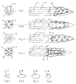
- FIGS. 1 to 4 each schematically show a fuel nozzle 1 which, in all exemplary embodiments, is arranged centrally in an air supply duct 2.
- the combustible material emerging from the fuel nozzle 1 is to be burned while supplying the combustion air emerging from the air supply duct 2, it also being conceivable that primary air has already been added to the combustible substance supplied to the fuel nozzle 1.
- a delta-shaped vortex installation surface 3 is arranged in the first exemplary embodiment according to FIG. 1, which is oriented obliquely to the flow direction of the fuel and the combustion air and has such large dimensions that, according to the end view in FIG lies in the flow cross-section of the fuel as well as the combustion air.
- a total of four triangular vortex installation surfaces 4 are arranged behind the annular mouth of the air supply duct 2. These vortex installation surfaces 4, which are evenly distributed over the circumference of the air supply duct 2, also produce leading edge vortex systems, as shown in the right part of FIG Complete combustion is also achieved in this case.
- the third exemplary embodiment according to FIG. 3 shows an arrangement of a likewise triangular swirl installation surface 5 which deviates from the above described exemplary embodiments.
- This also results in an intensive mixing of fuel and combustion air due to a stationary leading edge vortex system, which is primarily generated in the flow of fuel, but causes an intensive admixture of the combustion air surrounding the fuel by the stationary vortex, so that even in this embodiment within a very short mixing distance such a sufficient admixture of combustion air to the fuel that there is a complete combustion of the combustible material.
- swirl installation surfaces 6 and 7 are arranged both within the mouth of the fuel nozzle 1 and the air supply duct 2.
- a total of six triangular swirl installation surfaces 7 are arranged uniformly distributed in the annular mouth region of the air supply duct 2.
- leading edge vortex systems with stationary vortices are generated both in the fuel emerging from the fuel nozzle 1 and in the combustion air emerging from the air supply duct 2, which altogether bring about a complete mixing of fuel and combustion air by their meeting within a very short mixing distance, so that this too Embodiment a complete combustion of the combustible material is achieved.
- 5 to 8 show preferred embodiments of the vortex installation surfaces.
- 5 shows a delta-shaped or triangular vortex installation surface 3 already shown in FIGS. 1 to 4, whereas the vortex installation surface 8 is designed as a rhombus.
- the vortex installation surface 6 according to FIG. 7 is - as already drawn in FIG. 4 - oval;
- Fig. 8 shows a circular vortex installation surface 9. All these embodiments have in common that when they are set at an acute angle to the direction of flow, they generate a vortex system with their first flowed leading edges, which consists of stationary vortexes and thus a very short mixing distance intensive but low-loss mixing results.
Landscapes
- Engineering & Computer Science (AREA)
- Chemical & Material Sciences (AREA)
- Combustion & Propulsion (AREA)
- Mechanical Engineering (AREA)
- General Engineering & Computer Science (AREA)
- Solid-Fuel Combustion (AREA)
- Air Supply (AREA)
- Lighters Containing Fuel (AREA)
- Control And Other Processes For Unpacking Of Materials (AREA)
Abstract
Description
- Die Erfindung betrifft eine Vorrichtung zum Verbrennen brennbarer Stoffe mit einer Brennstoffdüse und mindestens einem Luftzufuhrkanal zur separaten Zufuhr von Verbrennungsluft.
- Bei der Verbrennung brennbarer Stoffe hängt die Qualität der Verbrennung im wesentlichen von der rechtzeitigen und vollständigen Mischung des Stoffes mit der Verbrennungsluft ab. Eine unvollständige Verbrennung tritt immer dann auf, wenn eine zu späte und zu geringe Zufuhr von Sauerstoff in den sich ausbildenden Flammenkern erfolgt. Die Folge einer unvollständigen Verbrennung sind Rückstände des zu verbrennenden Stoffes im Rauchgas.
- Sofern die Verbrennung eines Stoffes zum Zwecke der Energieerzeugung erfolgt, verringert die unvollständige Verbrennung den Gesamtwirkungsgrad. Wird dagegen die Verbrennung der Stoffe zur Entsorgung von chemischen Stoffen verwendet, ergibt sich zusätzlich zur Wirkungsgradverschlechterung die Gefahr einer Umweltbelastung.
- Der Erfindung liegt die Aufgabe zugrunde, eine Vorrichtung zum Verbrennen brennbarer Stoffe, insbesondere zur Entsorgung von chemischen Stoffen durch Verbrennung zu schaffen, bei welcher der Brennstoff einer Brennstoffdüse und die Verbrennungsluft separat über mindestens einen Luftzufuhrkanal zugeführt wird und die auch bei schwierigen und sich verändernden Randbedingungen eine vollständige Verbrennung sicherstellen soll.
- Die Lösung dieser Aufgabenstellung durch die Erfindung ist dadurch gekennzeichnet, daß im Austrittsbereich der Brennstoffdüse und des Luftzufuhrkanals mindestens eine ein Vorderkantenwirbelsystem in der Verbrennungsluft und/oder im Brennstoffstrahl erzeugende Wirbeleinbaufläche angeordnet ist.
- Durch die erfindungsgemäße Anordnung mindestens einer Wirbeleinbaufläche ergibt sich ein Vorderkantenwirbelsystem, das durch eine gezielte, intensive und zeitlich frühe Zusammenführung von Brennstoff und Verbrennungsluft eine vollständige Verbrennung innerhalb des sich ausbildenden Flammenkerns erzeugt, so daß eine unvollständige Verbrennung mit der Folge von Brennstoffrückständen im Rauchgas unter allen Umständen vermieden wird.
- Die Wirbeleinbaufläche kann hierbei entweder im Strömungsquerschnitt der Verbrennungsluft oder des Brennstoffes angeordnet sein; sie kann innerhalb des Kanalquerschnittes für die Verbrennungsluft bzw. für den Brennstoff oder in Strömungsrichtung von Verbrennungsluft bzw. Brennstoff hinter dem Kanal angeordnet werden. Sofern die Anordnung der Wirbeleinbaufläche hinter dem eigentlichen Kanal erfolgt, kann eine Lage bzw. Ausbildung der Wirbeleinbaufläche im Strömungsquerschnitt sowohl der Verbrennungsluft als auch des Brennstoffes gewählt werden.
- Die Wirbeleinbaufläche zur Erzeugung des Vorderkantenwirbelsystems kann mit geraden oder gebogenen Vorderkanten ausgebildet sein, beispielsweise in der Form eines Deltas oder Rhombus oder einer Kreis- oder Ovalscheibe. Weiterhin ist es erfindungsgemäß möglich, mehrere derartige Wirbeleinbauflächen über den kreis- bzw. ringförmigen Strömungsquerschnitt des Brennstoffes und/oder der Verbrennungsluft verteilt anzuordnen.
- In jedem dieser Fälle erzeugt die Wirbeleinbaufläche ein stationäres, dreidimensionales Vorderkantenwirbelsystem, das für eine sehr schnelle und intensive Mischung von Brennstoff und Verbrennungsluft sorgt und damit Ursache für eine vollständige Verbrennung des Brennstoffes ist. Die jeweilige Gestaltung und Anordnung der Wirbeleinbaufläche bzw. Wirbeleinbauflächen kann hierbei auf den Einzelfall abgestimmt werden.
- Auf der Zeichnung sind mehrere Ausführungsbeispiele der erfindungsgemäßen Verbrennungsvorrichtung schematisch dargestellt, und zwar zeigen:
- Fig. 1
- ein erstes Ausführungsbeispiel anhand einer schematischen Seitenansicht sowie einer Vorderansicht bei Verwendung einer im Strömungsquerschnitt sowohl der Verbrennungsluft als auch des Brennstoffes angeordneten Wirbeleinbaufläche,
- Fig. 2
- eine der Fig. 1 entsprechende Darstellung einer zweiten Ausführungsform mit insgesamt vier im Strömungsquerschnitt hinter dem Luftzufuhrkanal angeordneten Wirbeleinbauflächen,
- Fig. 3
- eine weitere Darstellung entsprechend den Fig. 1 und 2 einer dritten Ausführungsform mit einer im Strömungsquerschnitt hinter der Brennstoffdüse angeordneten Wirbeleinbaufläche,
- Fig. 4
- eine den Fig. 1 bis 3 entsprechende Darstellung einer vierten Ausführungsform, bei der eine Wirbeleinbaufläche im Austrittsbereich der Brennstoffdüse und insgesamt sechs Wirbeleinbauflächen im Austrittsquerschnitt des Luftzufuhrkanals angeordnet sind,
- Fig. 5
- eine Draufsicht auf eine erste Ausführungsform einer Wirbeleinbaufläche,
- Fig. 6
- eine Draufsicht auf eine zweite Ausführungsform einer derartigen Wirbeleinbaufläche,
- Fig. 7
- eine Draufsicht auf eine ovale Wirbeleinbaufläche und
- Fig. 8
- eine Draufsicht auf eine kreisförmige Wirbeleinbaufläche.
- Die vier Ausführungsbeispiele gemäß den Fig. 1 bis 4 zeigen schematisch jeweils eine Brennstoffdüse 1, die bei allen Ausführungsbeispielen zentrisch in einem Luftzufuhrkanal 2 angeordnet ist. Der aus der Brennstoffdüse 1 austretende brennbare Stoff soll unter Zufuhr der aus dem Luftzufuhrkanal 2 austretenden Verbrennungsluft verbrannt werden, wobei es auch denkbar ist, daß bereits dem der Brennstoffdüse 1 zugeführten brennbaren Stoff Primärluft zugegeben worden ist.
- Um eine vollständige und rückstandsfreie Verbrennung zu erzielen, ist beim ersten Ausführungsbeispiel nach Fig. 1 eine deltaförmige Wirbeleinbaufläche 3 angeordnet, die schräg zur Strömungsrichtung des Brennstoffes und der Verbrennungsluft ausgerichtet ist und derart große Abmessungen aufweist, daß sie gemäß der Stirnansicht in Fig. 1 sowohl im Strömungsquerschnitt des Brennstoffes als auch der Verbrennungsluft liegt. Die beiden spitzwinklig zueinander verlaufenden Vorderkanten dieser Wirbeleinbaufläche 3 erzeugen ein stationäres Vorderkantenwirbelsystem, das innerhalb einer sehr kurzen Mischstrecke zu einer sehr intensiven Vermischung von Brennstoff und Verbrennungsluft führt. Dem Kern der in Fig. 1 eingezeichneten Flamme wird auf diese Weise rechtzeitig ausreichend viel Verbrennungsluft zugeführt, so daß sich eine rückstandsfreie Verbrennung ergibt.
- Beim zweiten Ausführungsbeispiel nach Fig. 2 sind insgesamt vier dreieckförmige Wirbeleinbauflächen 4 hinter der ringförmigen Mündung des Luftzufuhrkanals 2 angeordnet. Diese gleichmäßig über den Umfang des Luftzufuhrkanals 2 verteilten Wirbeleinbauflächen 4 erzeugen gemäß der Darstellung im rechten Teil der Fig. 2 ebenfalls Vorderkantenwirbelsysteme, welche die aus dem Luftzufuhrkanal 2 austretende Verbrennungsluft auf kurzer Mischstrecke der Strömung des aus der Brennstoffdüse 1 austretenden brennbaren Stoffes zumischen, so daß auch in diesem Fall eine vollständige Verbrennung erzielt wird.
- Das dritte Ausführungsbeispiel nach Fig. 3 zeigt eine von den voranstehend beschriebenen Ausführungsbeispielen abweichende Anordnung einer ebenfalls dreieckförmigen Wirbeleinbaufläche 5. Beim Ausführungsbeispiel nach Fig. 3 ist diese Wirbeleinbaufläche 5 in der Mündung des Luftzufuhrkanals 2, jedoch im Strömungsquerschnitt ausschließlich des aus der Brennstoffdüse 1 austretenden Brennstoffes angeordnet. Auch hierdurch ergibt sich eine intensive Vermischung von Brennstoff und Verbrennungsluft aufgrund eines stationären Vorderkantenwirbelsystems, das primär in der Strömung des Brennstoffes erzeugt wird, durch die stationären Wirbel jedoch eine intensive Zumischung der den Brennstoff umgebenden Verbrennungsluft bewirkt, so daß auch bei diesem Ausführungsbeispiel innerhalb einer sehr kurzen Mischstrecke eine derart ausreichende Zumischung von Verbrennungsluft zum Brennstoff erfolgt, daß sich eine vollständige Verbrennung des brennbaren Stoffes ergibt.
- Beim vierten Ausführungsbeispiel nach Fig. 4 ist eine Ausführungsform gezeigt, bei der Wirbeleinbauflächen 6 und 7 sowohl innerhalb der Mündung der Brennstoffdüse 1 als auch des Luftzufuhrkanals 2 angeordnet sind. Beim Ausführungsbeispiel befindet sich im Austrittsbereich der Brennstoffdüse 1 eine ovale Wirbeleinbaufläche 6, während im ringförmigen Mündungsbereich des Luftzufuhrkanals 2 insgesamt sechs dreieckförmige Wirbeleinbauflächen 7 gleichmäßig verteilt angeordnet sind. Bei dieser Ausführungsform werden sowohl in dem aus der Brennstoffdüse 1 austretenden Brennstoff als auch in der aus dem Luftzufuhrkanal 2 austretenden Verbrennungsluft Vorderkantenwirbelsysteme mit stationären Wirbeln erzeugt, die insgesamt durch ihr Zusammentreffen innerhalb einer sehr kurzen Mischstrecke eine vollständige Vermischung von Brennstoff und Verbrennungsluft bewirken, so daß auch bei dieser Ausführungsform eine vollständige Verbrennung des brennbaren Stoffes erreicht wird.
- Die Fig. 5 bis 8 zeigen bevorzugte Ausführungsformen der Wirbeleinbauflächen. Die Fig. 5 zeigt eine bereits in den Fig. 1 bis 4 dargestellte deltaförmige bzw. dreieckförmige Wirbeleinbaufläche 3, wogegen die Wirbeleinbaufläche 8 als Rhombus ausgeführt ist. Die Wirbeleinbaufläche 6 nach Fig. 7 ist - wie bereits in Fig. 4 gezeichnet - oval ausgeführt; die Fig. 8 zeigt eine kreisförmige Wirbeleinbaufläche 9. Allen diesen Ausführungsformen ist gemeinsam, daß sie, wenn sie unter einem spitzen Winkel zur Strömungsrichtung angestellt werden, mit ihren zuerst angeströmten Vorderkanten ein Wirbelsystem erzeugen, das aus stationären Wirbeln besteht und hierdurch auf sehr kurzer Mischstrecke eine intensive und dennoch verlustarme Vermischung zur Folge hat.
-
- 1
- Brennstoffdüse
- 2
- Luftzufuhrkanal
- 3
- deltaförmige Wirbeleinbaufläche
- 4
- dreieckförmige Wirbeleinbaufläche
- 5
- dreieckförmige Wirbeleinbaufläche
- 6
- ovale Wirbeleinbaufläche
- 7
- dreieckförmige Wirbeleinbaufläche
- 8
- rhombusförmige Wirbeleinbaufläche
- 9
- kreisförmige Wirbeleinbaufläche
Claims (8)
- Vorrichtung zum Verbrennen brennbarer Stoffe mit einer Brennstoffdüse und mindestens einem Luftzufuhrkanal zur separaten Zufuhr von Verbrennungsluft,
dadurch gekennzeichnet,
daß im Austrittsbereich der Brennstoffdüse (1) und des Luftzufuhrkanals (2) mindestens eine ein Vorderkantenwirbelsystem in der Verbrennungsluft und/oder im Brennstoffstrahl erzeugende Wirbeleinbaufläche (3,4,5,6,7) angeordnet ist. - Vorrichtung nach Anspruch 1, dadurch gekennzeichnet, daß die Wirbeleinbaufläche (4) im Strömungsquerschnitt der Verbrennungsluft angeordnet ist.
- Vorrichtung nach Anspruch 1, dadurch gekennzeichnet, daß die Wirbeleinbaufläche (5) im Strömungsquerschnitt des Brennstoffes angeordnet ist.
- Vorrichtung nach Anspruch 2 oder 3, dadurch gekennzeichnet, daß die Wirbeleinbaufläche (6,7) innerhalb des Kanalquerschnittes für die Verbrennungsluft bzw. für den Brennstoff angeordnet ist.
- Vorrichtung nach Anspruch 2 oder 3, dadurch gekennzeichnet, daß die Wirbeleinbaufläche (3,4,5) hinter dem Kanal für die Verbrennungsluft bzw. den Brennstoff angeordnet ist.
- Vorrichtung nach Anspruch 5, dadurch gekennzeichnet, daß die Wirbeleinbaufläche (3) hinter den Kanälen für die Verbrennungsluft und den Brennstoff im Strömungsquerschnitt sowohl der Verbrennungsluft als auch des Brennstoffes angeordnet ist.
- Vorrichtung nach mindestens einem der Ansprüche 1 bis 6, dadurch gekennzeichnet, daß die Wirbeleinbaufläche (3,8,6,9) mit geraden oder gebogenen Vorderkanten ausgebildet ist.
- Vorrichtung nach mindestens einem der Ansprüche 1 bis 7, dadurch gekennzeichnet, daß mehrere Wirbeleinbauflächen (4,6,7) über den kreis- bzw. ringförmigen Strömungsquerschnitt des Brennstoffes und/oder der Verbrennungsluft verteilt angeordnet sind.
Applications Claiming Priority (2)
| Application Number | Priority Date | Filing Date | Title |
|---|---|---|---|
| DE4121067A DE4121067A1 (de) | 1991-06-26 | 1991-06-26 | Vorrichtung zum verbrennen brennbarer stoffe |
| DE4121067 | 1991-06-26 |
Publications (3)
| Publication Number | Publication Date |
|---|---|
| EP0520163A2 true EP0520163A2 (de) | 1992-12-30 |
| EP0520163A3 EP0520163A3 (en) | 1993-05-12 |
| EP0520163B1 EP0520163B1 (de) | 1996-04-17 |
Family
ID=6434765
Family Applications (1)
| Application Number | Title | Priority Date | Filing Date |
|---|---|---|---|
| EP92107547A Revoked EP0520163B1 (de) | 1991-06-26 | 1992-05-05 | Vorrichtung zum Verbrennen brennbarer Stoffe |
Country Status (5)
| Country | Link |
|---|---|
| EP (1) | EP0520163B1 (de) |
| JP (1) | JPH05215315A (de) |
| AT (1) | ATE137002T1 (de) |
| DE (2) | DE4121067A1 (de) |
| ES (1) | ES2086575T3 (de) |
Cited By (2)
| Publication number | Priority date | Publication date | Assignee | Title |
|---|---|---|---|---|
| EP0619457A1 (de) * | 1993-04-08 | 1994-10-12 | ABB Management AG | Vormischbrenner |
| EP0619456A1 (de) * | 1993-04-08 | 1994-10-12 | ABB Management AG | Brennstoffzufuhrsystem für Brennkammer |
Families Citing this family (1)
| Publication number | Priority date | Publication date | Assignee | Title |
|---|---|---|---|---|
| DE19542521A1 (de) * | 1995-11-15 | 1997-05-22 | Ruhrgas Ag | Verfahren und Brenner zum Verbrennen eines Luft/Brennstoff-Gemisches |
Family Cites Families (5)
| Publication number | Priority date | Publication date | Assignee | Title |
|---|---|---|---|---|
| GB100896A (en) * | 1915-07-15 | 1917-03-22 | Grant D Bradshaw | Improvements in Stove and other Heating Burners. |
| DE2155345A1 (de) * | 1971-11-08 | 1973-05-17 | Plate Bonn Gmbh | Gasbrenner mit einstellbarem mischungsverhaeltnis |
| DE3232971A1 (de) * | 1982-09-04 | 1984-03-08 | Stettner & Co, 8560 Lauf | Einsatz fuer oefen oder heizkessel |
| DE3423243A1 (de) * | 1983-08-06 | 1985-02-14 | Joh. Vaillant Gmbh U. Co, 5630 Remscheid | Gasbrenner |
| DE3740858A1 (de) * | 1987-12-02 | 1989-06-15 | Siemens Ag | Brennkammer |
-
1991
- 1991-06-26 DE DE4121067A patent/DE4121067A1/de active Granted
-
1992
- 1992-05-05 AT AT92107547T patent/ATE137002T1/de not_active IP Right Cessation
- 1992-05-05 EP EP92107547A patent/EP0520163B1/de not_active Revoked
- 1992-05-05 DE DE59205996T patent/DE59205996D1/de not_active Revoked
- 1992-05-05 ES ES92107547T patent/ES2086575T3/es not_active Expired - Lifetime
- 1992-06-25 JP JP4206925A patent/JPH05215315A/ja active Pending
Cited By (6)
| Publication number | Priority date | Publication date | Assignee | Title |
|---|---|---|---|---|
| EP0619457A1 (de) * | 1993-04-08 | 1994-10-12 | ABB Management AG | Vormischbrenner |
| EP0619456A1 (de) * | 1993-04-08 | 1994-10-12 | ABB Management AG | Brennstoffzufuhrsystem für Brennkammer |
| US5433596A (en) * | 1993-04-08 | 1995-07-18 | Abb Management Ag | Premixing burner |
| CH687831A5 (de) * | 1993-04-08 | 1997-02-28 | Asea Brown Boveri | Vormischbrenner. |
| CH687832A5 (de) * | 1993-04-08 | 1997-02-28 | Asea Brown Boveri | Brennstoffzufuehreinrichtung fuer Brennkammer. |
| US5658358A (en) * | 1993-04-08 | 1997-08-19 | Abb Management Ag | Fuel supply system for combustion chamber |
Also Published As
| Publication number | Publication date |
|---|---|
| DE4121067C2 (de) | 1993-07-22 |
| EP0520163B1 (de) | 1996-04-17 |
| DE59205996D1 (de) | 1996-05-23 |
| JPH05215315A (ja) | 1993-08-24 |
| ATE137002T1 (de) | 1996-05-15 |
| ES2086575T3 (es) | 1996-07-01 |
| EP0520163A3 (en) | 1993-05-12 |
| DE4121067A1 (de) | 1993-01-14 |
Similar Documents
| Publication | Publication Date | Title |
|---|---|---|
| DE69421766T2 (de) | Wirbelmischvorrichtung für eine Brennkammer | |
| DE2947130C2 (de) | Brennstoffinjektor für ein Gasturbinentriebwerk | |
| DE3217674C2 (de) | Brennkammer für eine Gasturbine | |
| DE69831355T2 (de) | Kohlenstaubbrenner | |
| EP1064498B1 (de) | Gasturbinenbrenner | |
| EP0438682A2 (de) | Abgassystem mit einem Partikelfilter und einem Regenerierungsbrenner | |
| DE2950535A1 (de) | Brennkammer einer gasturbine mit vormisch/vorverdampf-elementen | |
| EP0775869B1 (de) | Vormischbrenner | |
| EP0619457A1 (de) | Vormischbrenner | |
| DE3038875A1 (de) | Muellverbrennungsanlage | |
| EP0641971A2 (de) | Verfahren zum Betrieb eines Vormischbrenners | |
| DE2552374C2 (de) | Brenner für flüssigen oder gasförmigen Brennstoff | |
| WO1999006767A1 (de) | Brenner | |
| WO1998001707A1 (de) | Brenner | |
| DE69618914T2 (de) | Brennstoff-Einspritzvorrichtung und -verfahren | |
| EP0520163B1 (de) | Vorrichtung zum Verbrennen brennbarer Stoffe | |
| DE2842047A1 (de) | Vorrichtung zur verteilung von kraftstoff | |
| DE1429133B1 (de) | Gasbrennerduese | |
| DE2933101C2 (de) | ||
| EP0961905B1 (de) | Vorrichtung und verfahren zum verbrennen von brennstoff | |
| DE3936105C2 (de) | Drallerzeuger für Drallbrenner | |
| EP0496094A2 (de) | Düse zum Zuführen von Sekundärluft | |
| DE29521184U1 (de) | Vorrichtung in einem ein Primärfluid führenden Kanal | |
| DE69020901T2 (de) | Gasbrenner. | |
| DE102008019117A1 (de) | Verfahren zum Betreiben eines Vormischbrenners und ein Vormischbrenner zur Durchführung des Verfahrens |
Legal Events
| Date | Code | Title | Description |
|---|---|---|---|
| PUAI | Public reference made under article 153(3) epc to a published international application that has entered the european phase |
Free format text: ORIGINAL CODE: 0009012 |
|
| AK | Designated contracting states |
Kind code of ref document: A2 Designated state(s): AT BE DE ES FR GB NL |
|
| PUAL | Search report despatched |
Free format text: ORIGINAL CODE: 0009013 |
|
| AK | Designated contracting states |
Kind code of ref document: A3 Designated state(s): AT BE DE ES FR GB NL |
|
| 17P | Request for examination filed |
Effective date: 19930408 |
|
| RAP1 | Party data changed (applicant data changed or rights of an application transferred) |
Owner name: BDAG BALCKE-DUERR AKTIENGESELLSCHAFT |
|
| 17Q | First examination report despatched |
Effective date: 19940906 |
|
| GRAA | (expected) grant |
Free format text: ORIGINAL CODE: 0009210 |
|
| PGFP | Annual fee paid to national office [announced via postgrant information from national office to epo] |
Ref country code: FR Payment date: 19960416 Year of fee payment: 5 |
|
| AK | Designated contracting states |
Kind code of ref document: B1 Designated state(s): AT BE DE ES FR GB NL |
|
| REF | Corresponds to: |
Ref document number: 137002 Country of ref document: AT Date of ref document: 19960515 Kind code of ref document: T |
|
| PGFP | Annual fee paid to national office [announced via postgrant information from national office to epo] |
Ref country code: GB Payment date: 19960418 Year of fee payment: 5 |
|
| ET | Fr: translation filed | ||
| PGFP | Annual fee paid to national office [announced via postgrant information from national office to epo] |
Ref country code: BE Payment date: 19960521 Year of fee payment: 5 |
|
| PGFP | Annual fee paid to national office [announced via postgrant information from national office to epo] |
Ref country code: AT Payment date: 19960522 Year of fee payment: 5 |
|
| REF | Corresponds to: |
Ref document number: 59205996 Country of ref document: DE Date of ref document: 19960523 |
|
| PGFP | Annual fee paid to national office [announced via postgrant information from national office to epo] |
Ref country code: NL Payment date: 19960529 Year of fee payment: 5 |
|
| PGFP | Annual fee paid to national office [announced via postgrant information from national office to epo] |
Ref country code: ES Payment date: 19960531 Year of fee payment: 5 |
|
| GBT | Gb: translation of ep patent filed (gb section 77(6)(a)/1977) |
Effective date: 19960509 |
|
| REG | Reference to a national code |
Ref country code: ES Ref legal event code: FG2A Ref document number: 2086575 Country of ref document: ES Kind code of ref document: T3 |
|
| PGFP | Annual fee paid to national office [announced via postgrant information from national office to epo] |
Ref country code: DE Payment date: 19960715 Year of fee payment: 5 |
|
| GRAH | Despatch of communication of intention to grant a patent |
Free format text: ORIGINAL CODE: EPIDOS IGRA |
|
| PLBQ | Unpublished change to opponent data |
Free format text: ORIGINAL CODE: EPIDOS OPPO |
|
| PLBI | Opposition filed |
Free format text: ORIGINAL CODE: 0009260 |
|
| PLBQ | Unpublished change to opponent data |
Free format text: ORIGINAL CODE: EPIDOS OPPO |
|
| PLBI | Opposition filed |
Free format text: ORIGINAL CODE: 0009260 |
|
| PLBF | Reply of patent proprietor to notice(s) of opposition |
Free format text: ORIGINAL CODE: EPIDOS OBSO |
|
| 26 | Opposition filed |
Opponent name: JOH. VAILLANT GMBH U. CO. Effective date: 19970107 |
|
| 26 | Opposition filed |
Opponent name: ASEA BROWN BOVERI AG Effective date: 19970116 Opponent name: JOH. VAILLANT GMBH U. CO. Effective date: 19970107 |
|
| NLR1 | Nl: opposition has been filed with the epo |
Opponent name: ASEA BROWN BOVERI AG Opponent name: JOH. VAILLANT GMBH U. CO. |
|
| PLBF | Reply of patent proprietor to notice(s) of opposition |
Free format text: ORIGINAL CODE: EPIDOS OBSO |
|
| RDAH | Patent revoked |
Free format text: ORIGINAL CODE: EPIDOS REVO |
|
| RDAG | Patent revoked |
Free format text: ORIGINAL CODE: 0009271 |
|
| STAA | Information on the status of an ep patent application or granted ep patent |
Free format text: STATUS: PATENT REVOKED |
|
| 27W | Patent revoked |
Effective date: 19970530 |
|
| GBPR | Gb: patent revoked under art. 102 of the ep convention designating the uk as contracting state |
Free format text: 970530 |
|
| NLR2 | Nl: decision of opposition |