EP0520221B1 - Elektronisch geschaltete Steckdose - Google Patents
Elektronisch geschaltete Steckdose Download PDFInfo
- Publication number
- EP0520221B1 EP0520221B1 EP92109434A EP92109434A EP0520221B1 EP 0520221 B1 EP0520221 B1 EP 0520221B1 EP 92109434 A EP92109434 A EP 92109434A EP 92109434 A EP92109434 A EP 92109434A EP 0520221 B1 EP0520221 B1 EP 0520221B1
- Authority
- EP
- European Patent Office
- Prior art keywords
- conductor
- branch
- load
- circuit
- power
- Prior art date
- Legal status (The legal status is an assumption and is not a legal conclusion. Google has not performed a legal analysis and makes no representation as to the accuracy of the status listed.)
- Expired - Lifetime
Links
Images

Classifications
-
- H—ELECTRICITY
- H02—GENERATION; CONVERSION OR DISTRIBUTION OF ELECTRIC POWER
- H02J—ELECTRIC POWER NETWORKS; CIRCUIT ARRANGEMENTS OR SYSTEMS FOR SUPPLYING OR DISTRIBUTING ELECTRIC POWER; SYSTEMS FOR STORING ELECTRIC ENERGY
- H02J3/00—Circuit arrangements for AC mains or AC distribution networks
- H02J3/26—Arrangements for eliminating or reducing asymmetry in polyphase networks
-
- Y—GENERAL TAGGING OF NEW TECHNOLOGICAL DEVELOPMENTS; GENERAL TAGGING OF CROSS-SECTIONAL TECHNOLOGIES SPANNING OVER SEVERAL SECTIONS OF THE IPC; TECHNICAL SUBJECTS COVERED BY FORMER USPC CROSS-REFERENCE ART COLLECTIONS [XRACs] AND DIGESTS
- Y02—TECHNOLOGIES OR APPLICATIONS FOR MITIGATION OR ADAPTATION AGAINST CLIMATE CHANGE
- Y02E—REDUCTION OF GREENHOUSE GAS [GHG] EMISSIONS, RELATED TO ENERGY GENERATION, TRANSMISSION OR DISTRIBUTION
- Y02E40/00—Technologies for an efficient electrical power generation, transmission or distribution
- Y02E40/50—Arrangements for eliminating or reducing asymmetry in polyphase networks
Definitions
- This invention relates to electrical outlet receptacles and, more particularly, to an electronic switching circuit for such a receptacle.
- a typical distribution system often includes a single source of power providing power to plural electrical branch circuits.
- the branch circuits may provide power at equal voltage levels, as required.
- a typical power distribution system might include a polyphase power source in a wye configuration.
- the voltage across any pair of windings is 208 volts AC, while the voltage between any single terminal and a common or neutral point is 120 volts AC.
- the branch circuits may comprise any combination of the above.
- the present invention is intended to solve one or more of the problems discussed above in a novel and simple manner.
- a power switching circuit for selectively connecting an electrical load to any one of a plurality of branch power circuits.
- an electrical outlet receptacle power switching circuit for selectively connecting an electrical load having first and second input connections to any one of a plurality of branch power circuits.
- Each branch circuit includes a first and second conductor defining a relative voltage therebetween.
- the power switching circuit includes a user actuable means for selecting, when between the phases of the AC system a load unbalance occurs, which of the branch circuits is to be connected to the load.
- First switch means are electrically connected to the first conductor of each branch circuit and to the first input connection of the load for selectively electrically connecting one of the first conductors to the first input connection.
- a second switch means is electrically connected to the second conductor of each branch circuit and to the second input connection of the load for selectively electrically connecting one of the second conductors to the second input connection.
- a control means is operated by the user actuable or automatic load sensing means for controlling the first switch means and the second switch means to connect the respective first and second conductors of the select branch circuit to the load first and second input connections.
- the first and second switch means comprises a plurality of triacs, two for each branch circuit.
- control means comprises a plurality of optocouplers, one for each triac.
- the actuating means comprises a manually operated selector switch or an electronic selector switch actuated by a load sensing means.
- control means is electrically powered by one of the branch circuits.
- the electrical outlet receptacle power switching circuit comprises actuating means for selecting which of the branch circuits is to be connected to the load.
- a plurality of electrically controlled switches are each connected between the first conductor of the one branch circuit and to the first input connection of the load each for selectively electrically connecting or disconnecting the first conductor connected thereto to the first input connection.
- a plurality of electrically controlled switches are each connected between the second conductor of one of the branch circuits and to the second input connection of the load, each for selectively electrically connecting or disconnecting the second conductor connected thereto to the second input connection.
- a control means is operated by the actuating means for controlling the electrically controlled switches to connect the respective first and second conductors of the selected branch circuit to the load first and second input connections.
- the power distribution system 10 includes a power source illustrated schematically in the form of a three phase wye connected winding 12.
- the winding 12 includes three phase terminals 14-16 and a common or neutral terminal 18.
- the first phase terminal 14 is connected to a conductor labelled L1.
- the second phase terminal 15 is connected to a conductor labelled L2.
- the third phase terminal 16 is connected to a conductor labelled L3.
- the neutral terminal 18 is connected to three conductors labelled N1-N3.
- the voltage developed across any pair of phase terminals, i.e., terminals 14 and 15 is on the order of 208 volts AC, while the voltage between any phase terminal 14-16 and the neutral terminal 18 is 120 volts AC.
- the power distribution system 10 includes three branch circuits 19-1 to 19-3.
- Each branch circuit referred to generically as 19, includes a respective phase conductor L1-L3 and an associated respective neutral conductor N1-N3.
- the three branch circuits 19, each at 120 volts AC, power a plurality of N switched power receptacles 20-1 through 20-N.
- Each of the switched power receptacles referred to generally as numeral 20, operates to connect a load to one of the branch circuits 19 as selected by the electronic selector switch actuated by a load sensing means or by a user.
- the switched power receptacle 20 utilizes 120 volt AC power. Nevertheless, the teachings of the invention could be utilized in connection with a switched power receptacle operating off of 208 volts AC, as necessary or desired.
- the switched power receptacle 20 includes a power source, represented schematically at 22, connected to a movable contact 25 of a user actuable selector switch 24.
- the selector switch 24 is a three position selector switch, one position for each branch circuit 19-1 to 19-3.
- the selector switch selectively connects the power source 22 via the movable contact 25 to one of three conductors 26-28.
- the selector switch 24 is used for selecting which branch circuit 19 is to be connected to a load in the form of an outlet receptacle 30 having first and second input connections 32 and 34, respectively.
- the power switched receptacle 20 includes three hot electronic switch circuits 36-38. Each electronic switch circuit 36-38 is connected between the "L" or hot conductor of one of the branch circuits 19 and the first input connection 32 of the outlet 30. For example, the first hot electronic switch circuit 36 is connected to the conductor L1 to selectively connect or disconnect the conductor L1 to the outlet first input connection 32.
- the power switched receptacle 20 also includes three neutral electronic switch circuits 40-42. Each electronic switch circuit 40-42 is connected between the neutral or N conductor of one of the branch circuits 19 and the second input connection 34 of the outlet 30. For example, the first neutral electronic switch circuit 40 is connected to the conductor N1 to selectively connect or disconnect the conductor N1 to the outlet second input connection 34.
- the first switch conductor 26 is connected to the first electronic switch circuits 36 and 40 for controlling the same.
- the second switch conductor 27 is connected to the second electronic switch circuits 37 and 41, while the third switched conductor 28 is connected to the remaining electronic switch circuits 38 and 42.
- the selector switch 24 selects which of the hot electronic switch circuits 36-38 and corresponding neutral electronic switch circuits 40-42 are used to connect the selected branch circuit 19 to the outlet 30.
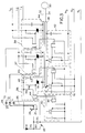
- the power switched receptacle 20 is illustrated in greater detail.
- the power supply 22 is powered by the first branch circuit 19-1, i.e. the voltage supplied between the neutral conductor N1 and the hot conductor L1.
- the power supply 22 comprises a diode D1 connected between the conductor L1 and series connected resistors R1 and R2 to the first branch circuit neutral conductor N1.
- a capacitor C1 is connected across the resistor R2.
- the junction between the resistors R1 and R2 is connected to the movable contact 25 of the switch 24.
- a respective LED L1-L3 is connected in line with the respective switch conductors 26-28 to provide an indication as to the position of the movable contact 25.
- the first hot electronic switch circuit 36 includes a triac S1 having a gate G and terminals T1 and T2.
- the terminal T1 is connected to the first branch hot conductor L1.
- the terminal T2 is connected to a heat sink 42 for dissipating heat in the triac S1 and for providing electrical conduction to the outlet first input connection 32.
- the gate G is connected to a pin 4 of a driver circuit 44.
- the driver circuit 44 comprises an optically driven triac, such as a Motorola Type MOC3041 circuit. Particularly, the circuit 44 comprises a zero-crossing triac driver circuit triggered by a current through terminals 1 and 2 supplied from the first switch conductor 26.
- the driver circuit 44 sends a current pulse to the triac S1 on each half cycle during triggering. This current pulse turns on the triac S1.
- the pulse is applied to the triac S1 near the zero voltage phase of the 120 volt AC wave reducing the generation of EMI.
- a resistor R3 is connected between the branch conductor L1 and terminal 5 of the driver circuit 44 to provide current limiting to prevent overdriving the LED L1.
- a resistor R4 is connected between the triac gate G and terminal T1 to help turn off the SCR by eliminating a floating gate condition.
- a phase correction circuit 46 comprising a series resistor R5 and capacitor C2 is connected between the branch conductor L1 and the triac terminal T2. The phase correction circuit is necessary if there is switching from one branch circuit to another when an inductive load is connected to the receptacle 30.
- Each of the other hot electronic switch circuits 37 and 38 is identical to the circuit 36 and therefore is not discussed in detail. The only difference is that the respective circuits 37 and 38 are driven by the switch conductors 27 and 28 and are powered by the respective branch circuit conductors L2 and L3.
- the neutral electronic switch circuits 40-42 are virtually identical to the corresponding hot electronic switch circuits 36-38, respectively.
- the driver circuit 44 see the circuit 40, has terminals 1 and 2 connected between terminal 2 of the driver circuit 44 of the electronic switch circuit 36 and the first branch circuit neutral conductor N1.
- the trigger circuit 44 of each first electronic switch circuit 36 and 40 for the first branch circuit are series connected to ensure that the associated triacs are turned on and off concurrently.
- the driver circuits 44 which are operated by the user actuable selector switch 24 control the triacs S1 to connect the L and N conductors of the selected branch circuit to the outlet receptacle first and second input connections 32 and 34, respectively.
- the selector switch 24 may be provided remotely from the outlet receptacle 30 or may be provided on a face plate associated therewith.
- the selector switch 24 may comprise any known form of switch suitable for directing a low voltage current to any one pair of the three pairs, i.e. 36 and 40, 37 and 41, and 38 and 42, of electronic switch circuits. Doing so energizes the gate of the associated triac S1 allowing a high voltage current to travel therethrough to the outlet receptacle 30.
- the manually operated selector switch 24 may be replaced by an electronic selector switch actuated by load sensing means.
- the heat sink 44 is connected to all the hot line triacs of the circuits 36-38 while a heat sink 48 is connected to the triacs S1 of the neutral circuits 40-42 without requiring insulation between the heat sinks 44, 48 and the triacs S1.
- the two heat sinks 44 and 48 act as conductors to the outlet receptacle 30 and require insulation therebetween and any other metal parts of the assembly.
- a switched power receptacle which switches an outlet receptacle to both the hot and neutral sides of any one of a plurality of branch circuits.
Landscapes
- Engineering & Computer Science (AREA)
- Power Engineering (AREA)
- Details Of Connecting Devices For Male And Female Coupling (AREA)
- Supply And Distribution Of Alternating Current (AREA)
- Remote Monitoring And Control Of Power-Distribution Networks (AREA)
- Driving Mechanisms And Operating Circuits Of Arc-Extinguishing High-Tension Switches (AREA)
Claims (6)
- Elektrische Leistungsumschalt-Schaltung für Steckdosen zum ausgewählten Verbinden einer elektrischen Last (30) mit einem ersten und einem zweiten Eingangsanschluß (32, 34) mit irgendeinem aus einer Vielzahl von Speisestromkreisen (19), wobei jeder Speisestromkreis (19) einen ersten und einen zweiten Leiter (L, N), zwischen welchen eine Spannungsdifferenz definiert wird, umfaßt, mit:
einer Betätigungseinrichtung (24) zum Auswählen, welcher der Speisestromkreise (19) mit der Last (30) zu verbinden ist, wenn zwischen den Speisestromkreisen des Wechselstrom-Speisesystems mit drei verschiedenen Speisestromkreisen ein Lastungleichgewicht auftritt,
einer Vielzahl elektrisch gesteuerter Schaltern (S1), von denen jeder zwischen dem ersten Leiter (L) eines der Speisestromkreise (19) und dem ersten Eingangsanschluß (32) der Last (30) angeschlossen ist, wobei jeder den ersten an diesen angeschlossenen Leiter (L) mit dem ersten Eingangsanschluß (32) elektrisch verbinden oder die Verbindung aufheben kann,
einer Vielzahl elektrisch gesteuerter Schalter (S1), von denen jeder zwischen dem zweiten Leiter (N) eines der Speisestromkreise (19) und dem zweiten Eingangsanschluß (34) der Last (30) angeschlossen ist, wobei jeder den an diesen angeschlossenen zweiten Leiter (N) mit dem zweiten Eingangsanschluß (34) elektrisch verbinden oder die Verbindung aufheben kann, und
einer Steuereinrichtung (44), welche durch die Betätigungseinrichtung (24) betätigt wird zum Steuern der elektrisch gesteuerten Schalter (S1), um den jeweiligen ersten und zweiten Leiter (L, N) des ausgewählten Speisestromkreises (19) mit dem ersten und dem zweiten Eingangsanschluß (32, 34) der Last zu verbinden. - Leistungsumschalt-Schaltung nach Anspruch 1,
bei welcher jeder von den ersten und zweiten elektrisch gesteuerten Schaltern einen Schalt-Triac (S1) umfaßt. - Leistungsumschalt-Schaltung nach Anspruch 2,
bei welcher die Steuereinrichtung eine Vielzahl von optisch getriebenen Triacs (44), einen für jeden der Schalttriacs (S1), umfaßt. - Leistungsumschalt-Schaltung nach Anspruch 1,
bei welcher die Betätigungseinrichtung einen manuell betätigten Auswahlschalter (24) umfaßt. - Leistungsumschalt-Schaltung nach Anspruch 1,
bei welcher die Betätigungseinrichtung einen durch eine Last-Abfühleinrichtung betätigten elektronischen Auswahlschalter umfaßt. - Leistungsumschalt-Schaltung nach Anspruch 1,
bei welcher die Steuereinrichtung durch einen der Speisestromkreise (L, N) elektrisch gespeist wird.
Applications Claiming Priority (2)
| Application Number | Priority Date | Filing Date | Title |
|---|---|---|---|
| US07/714,485 US5498915A (en) | 1991-06-13 | 1991-06-13 | Electronically switched power receptacle |
| US714485 | 1991-06-13 |
Publications (2)
| Publication Number | Publication Date |
|---|---|
| EP0520221A1 EP0520221A1 (de) | 1992-12-30 |
| EP0520221B1 true EP0520221B1 (de) | 1995-12-20 |
Family
ID=24870238
Family Applications (1)
| Application Number | Title | Priority Date | Filing Date |
|---|---|---|---|
| EP92109434A Expired - Lifetime EP0520221B1 (de) | 1991-06-13 | 1992-06-04 | Elektronisch geschaltete Steckdose |
Country Status (4)
| Country | Link |
|---|---|
| US (1) | US5498915A (de) |
| EP (1) | EP0520221B1 (de) |
| JP (2) | JPH0654449A (de) |
| DE (1) | DE69206896T2 (de) |
Families Citing this family (12)
| Publication number | Priority date | Publication date | Assignee | Title |
|---|---|---|---|---|
| US5281859A (en) * | 1991-06-13 | 1994-01-25 | Molex Incorporated | Automatically switched power receptacle |
| US5604385A (en) * | 1995-05-22 | 1997-02-18 | Target Hi-Tech Electronics Ltd. | Apparatus for and method of evenly distributing an electrical load across a three phase power distribution network |
| US6018203A (en) * | 1995-05-22 | 2000-01-25 | Target Hi-Tech Electronics Ltd. | Apparatus for and method of evenly distributing an electrical load across an n-phase power distribution network |
| US5844326A (en) * | 1997-06-23 | 1998-12-01 | Cruising Equipment Company, Inc. | Managed electrical outlet for providing rank-ordered over-current protection |
| KR19990078487A (ko) * | 1998-10-20 | 1999-11-05 | 주진용 | 자동 절전장치 |
| US20050252753A1 (en) | 2004-05-13 | 2005-11-17 | Leo Robert J | Double pull LED outlet switch |
| US20060158040A1 (en) * | 2005-01-19 | 2006-07-20 | Mcintosh Jason | Configurable electrical outlet |
| CN105553087A (zh) * | 2007-03-14 | 2016-05-04 | 佐尼特结构解决方案有限责任公司 | 用于将电力输送到具有电源线的设备的装置和方法 |
| CA2681099C (en) * | 2007-03-14 | 2016-11-29 | Zonit Structured Solutions, Llc | Automatic transfer switch module |
| US20100230266A1 (en) * | 2009-03-14 | 2010-09-16 | Vestyck Daniel J | Configurable Electrical Outlet Receptacle |
| US9081568B1 (en) * | 2012-09-25 | 2015-07-14 | Amazon Technologies, Inc. | Electrical power system with automatic transfer switch failure protection |
| FR3006516A1 (fr) * | 2013-05-28 | 2014-12-05 | Commissariat Energie Atomique | Selection de phase pour installation electrique polyphasee |
Family Cites Families (8)
| Publication number | Priority date | Publication date | Assignee | Title |
|---|---|---|---|---|
| US3732486A (en) * | 1971-12-29 | 1973-05-08 | Gen Electric | Electrical apparatus with thyristor circuit |
| US3748492A (en) * | 1972-05-25 | 1973-07-24 | Massachusetts Inst Technology | Light-triggered electric power source |
| SU679961A1 (ru) * | 1975-10-17 | 1979-08-15 | Горьковский политехнический институт им.А.А.Жданова | Способ регулировани переменного напр жени |
| JPS5895945A (ja) * | 1981-12-02 | 1983-06-07 | 三菱レイヨン株式会社 | 三相受電単相負荷平衡制御回路 |
| US4594515A (en) * | 1984-06-11 | 1986-06-10 | Universal Metal Industries | Switching circuit |
| JPS6149334A (ja) * | 1984-08-16 | 1986-03-11 | オムロン株式会社 | 多極負荷開閉装置 |
| FR2590741B1 (fr) * | 1985-11-26 | 1988-03-04 | Eurotherm Automation Sa | Procede et dispositif de commande de l'alimentation de charges a partir d'un reseau triphase |
| DE3933202A1 (de) * | 1989-10-05 | 1991-04-11 | Philips Patentverwaltung | Schaltungsanordnung zum speisen einer last |
-
1991
- 1991-06-13 US US07/714,485 patent/US5498915A/en not_active Expired - Fee Related
-
1992
- 1992-06-03 JP JP4168520A patent/JPH0654449A/ja active Pending
- 1992-06-04 DE DE69206896T patent/DE69206896T2/de not_active Expired - Fee Related
- 1992-06-04 EP EP92109434A patent/EP0520221B1/de not_active Expired - Lifetime
-
1998
- 1998-04-10 JP JP002798U patent/JPH1146U/ja active Pending
Also Published As
| Publication number | Publication date |
|---|---|
| JPH0654449A (ja) | 1994-02-25 |
| EP0520221A1 (de) | 1992-12-30 |
| US5498915A (en) | 1996-03-12 |
| DE69206896T2 (de) | 1996-08-14 |
| JPH1146U (ja) | 1999-03-26 |
| DE69206896D1 (de) | 1996-02-01 |
Similar Documents
| Publication | Publication Date | Title |
|---|---|---|
| KR960001071B1 (ko) | 전자적으로 스위칭되는 전력 리셉터클 | |
| US5281859A (en) | Automatically switched power receptacle | |
| EP0188886B1 (de) | Heizapparat | |
| US5731947A (en) | Electricity tapping apparatus which automatically turns on the slave units by sensing the power status of the master unit | |
| US5498915A (en) | Electronically switched power receptacle | |
| CA2092442C (en) | Ac/dc-converter | |
| US8619443B2 (en) | System and method to boost voltage | |
| MX2010012183A (es) | Conmutacion paralela de ca con control secuencial. | |
| US4352993A (en) | Multiple position power switch | |
| JP4267826B2 (ja) | 電圧切換え装置 | |
| WO2012044289A1 (en) | System and method to boost voltage | |
| US3585471A (en) | Multifrequency, multivoltage stator circuits for alternating current motors | |
| US5667704A (en) | Multiple sequence welding controller | |
| KR102430761B1 (ko) | 잔광 방지 장치 | |
| JP4542735B2 (ja) | 電圧源コンバータの付勢装置 | |
| US4706179A (en) | Arrangement for switching rectified alternating current | |
| RU2215320C2 (ru) | Устройство для стабилизации и симметрирования трехфазного напряжения | |
| CN1937352A (zh) | 具有防过热功能的电子式自动切换开关 | |
| GB2215536A (en) | Three-phase electrical power control system for multiple loads | |
| US5708357A (en) | Power circuit for electronic controller | |
| JP2000050503A (ja) | 電圧線切換スイッチ | |
| FI81001B (fi) | Elektrisk bastuugn. | |
| KR900006947B1 (ko) | 순차제어형 교류전원 분배장치 | |
| KR20050026934A (ko) | 전압 제어 방법 및 장치 | |
| JP2712297B2 (ja) | 誘導加熱調理器 |
Legal Events
| Date | Code | Title | Description |
|---|---|---|---|
| PUAI | Public reference made under article 153(3) epc to a published international application that has entered the european phase |
Free format text: ORIGINAL CODE: 0009012 |
|
| AK | Designated contracting states |
Kind code of ref document: A1 Designated state(s): DE FR GB IT |
|
| 17P | Request for examination filed |
Effective date: 19930616 |
|
| 17Q | First examination report despatched |
Effective date: 19941209 |
|
| GRAA | (expected) grant |
Free format text: ORIGINAL CODE: 0009210 |
|
| ITF | It: translation for a ep patent filed | ||
| AK | Designated contracting states |
Kind code of ref document: B1 Designated state(s): DE FR GB IT |
|
| REF | Corresponds to: |
Ref document number: 69206896 Country of ref document: DE Date of ref document: 19960201 |
|
| ET | Fr: translation filed | ||
| PLBE | No opposition filed within time limit |
Free format text: ORIGINAL CODE: 0009261 |
|
| STAA | Information on the status of an ep patent application or granted ep patent |
Free format text: STATUS: NO OPPOSITION FILED WITHIN TIME LIMIT |
|
| 26N | No opposition filed | ||
| PGFP | Annual fee paid to national office [announced via postgrant information from national office to epo] |
Ref country code: GB Payment date: 20010502 Year of fee payment: 10 |
|
| PGFP | Annual fee paid to national office [announced via postgrant information from national office to epo] |
Ref country code: FR Payment date: 20010531 Year of fee payment: 10 |
|
| PGFP | Annual fee paid to national office [announced via postgrant information from national office to epo] |
Ref country code: DE Payment date: 20010627 Year of fee payment: 10 |
|
| REG | Reference to a national code |
Ref country code: GB Ref legal event code: IF02 |
|
| PG25 | Lapsed in a contracting state [announced via postgrant information from national office to epo] |
Ref country code: GB Free format text: LAPSE BECAUSE OF NON-PAYMENT OF DUE FEES Effective date: 20020604 |
|
| PG25 | Lapsed in a contracting state [announced via postgrant information from national office to epo] |
Ref country code: DE Free format text: LAPSE BECAUSE OF NON-PAYMENT OF DUE FEES Effective date: 20030101 |
|
| GBPC | Gb: european patent ceased through non-payment of renewal fee |
Effective date: 20020604 |
|
| PG25 | Lapsed in a contracting state [announced via postgrant information from national office to epo] |
Ref country code: FR Free format text: LAPSE BECAUSE OF NON-PAYMENT OF DUE FEES Effective date: 20030228 |
|
| REG | Reference to a national code |
Ref country code: FR Ref legal event code: ST |
|
| PG25 | Lapsed in a contracting state [announced via postgrant information from national office to epo] |
Ref country code: IT Free format text: LAPSE BECAUSE OF NON-PAYMENT OF DUE FEES;WARNING: LAPSES OF ITALIAN PATENTS WITH EFFECTIVE DATE BEFORE 2007 MAY HAVE OCCURRED AT ANY TIME BEFORE 2007. THE CORRECT EFFECTIVE DATE MAY BE DIFFERENT FROM THE ONE RECORDED. Effective date: 20050604 |