EP0520302B1 - Dispositif de commande d'un système d'essuie-glaces - Google Patents
Dispositif de commande d'un système d'essuie-glaces Download PDFInfo
- Publication number
- EP0520302B1 EP0520302B1 EP92110175A EP92110175A EP0520302B1 EP 0520302 B1 EP0520302 B1 EP 0520302B1 EP 92110175 A EP92110175 A EP 92110175A EP 92110175 A EP92110175 A EP 92110175A EP 0520302 B1 EP0520302 B1 EP 0520302B1
- Authority
- EP
- European Patent Office
- Prior art keywords
- screen
- controlling
- wiping system
- setting
- converter
- Prior art date
- Legal status (The legal status is an assumption and is not a legal conclusion. Google has not performed a legal analysis and makes no representation as to the accuracy of the status listed.)
- Expired - Lifetime
Links
- 230000005693 optoelectronics Effects 0.000 claims description 12
- 239000011248 coating agent Substances 0.000 claims description 5
- 238000000576 coating method Methods 0.000 claims description 5
- 238000012545 processing Methods 0.000 claims description 4
- 238000004140 cleaning Methods 0.000 claims description 2
- 230000005855 radiation Effects 0.000 description 28
- 238000012937 correction Methods 0.000 description 8
- 230000005540 biological transmission Effects 0.000 description 5
- 239000011521 glass Substances 0.000 description 5
- 230000003287 optical effect Effects 0.000 description 5
- 238000010586 diagram Methods 0.000 description 4
- 230000000694 effects Effects 0.000 description 4
- 230000006978 adaptation Effects 0.000 description 2
- 230000008859 change Effects 0.000 description 2
- 230000008878 coupling Effects 0.000 description 2
- 238000010168 coupling process Methods 0.000 description 2
- 238000005859 coupling reaction Methods 0.000 description 2
- 238000013016 damping Methods 0.000 description 2
- 230000001419 dependent effect Effects 0.000 description 2
- 238000011156 evaluation Methods 0.000 description 2
- 230000006870 function Effects 0.000 description 2
- 238000005259 measurement Methods 0.000 description 2
- 230000035945 sensitivity Effects 0.000 description 2
- 230000003679 aging effect Effects 0.000 description 1
- 230000015572 biosynthetic process Effects 0.000 description 1
- 230000000550 effect on aging Effects 0.000 description 1
- 238000009413 insulation Methods 0.000 description 1
- 230000003993 interaction Effects 0.000 description 1
- 230000002452 interceptive effect Effects 0.000 description 1
- 239000007788 liquid Substances 0.000 description 1
- 238000004519 manufacturing process Methods 0.000 description 1
- 238000000034 method Methods 0.000 description 1
- 230000008569 process Effects 0.000 description 1
- 230000004044 response Effects 0.000 description 1
- 239000007787 solid Substances 0.000 description 1
- 230000003068 static effect Effects 0.000 description 1
- 239000004575 stone Substances 0.000 description 1
- 230000002277 temperature effect Effects 0.000 description 1
- 238000009736 wetting Methods 0.000 description 1
Images

Classifications
-
- B—PERFORMING OPERATIONS; TRANSPORTING
- B60—VEHICLES IN GENERAL
- B60S—SERVICING, CLEANING, REPAIRING, SUPPORTING, LIFTING, OR MANOEUVRING OF VEHICLES, NOT OTHERWISE PROVIDED FOR
- B60S1/00—Cleaning of vehicles
- B60S1/02—Cleaning windscreens, windows or optical devices
- B60S1/04—Wipers or the like, e.g. scrapers
- B60S1/06—Wipers or the like, e.g. scrapers characterised by the drive
- B60S1/08—Wipers or the like, e.g. scrapers characterised by the drive electrically driven
- B60S1/0818—Wipers or the like, e.g. scrapers characterised by the drive electrically driven including control systems responsive to external conditions, e.g. by detection of moisture, dirt or the like
-
- B—PERFORMING OPERATIONS; TRANSPORTING
- B60—VEHICLES IN GENERAL
- B60S—SERVICING, CLEANING, REPAIRING, SUPPORTING, LIFTING, OR MANOEUVRING OF VEHICLES, NOT OTHERWISE PROVIDED FOR
- B60S1/00—Cleaning of vehicles
- B60S1/02—Cleaning windscreens, windows or optical devices
- B60S1/04—Wipers or the like, e.g. scrapers
- B60S1/06—Wipers or the like, e.g. scrapers characterised by the drive
- B60S1/08—Wipers or the like, e.g. scrapers characterised by the drive electrically driven
- B60S1/0818—Wipers or the like, e.g. scrapers characterised by the drive electrically driven including control systems responsive to external conditions, e.g. by detection of moisture, dirt or the like
- B60S1/0822—Wipers or the like, e.g. scrapers characterised by the drive electrically driven including control systems responsive to external conditions, e.g. by detection of moisture, dirt or the like characterized by the arrangement or type of detection means
- B60S1/0833—Optical rain sensor
Definitions
- the present invention is based on a device for controlling a windshield wiper system designed according to the preamble of the main claim.
- Such devices are particularly intended for qualitatively and quantitatively detecting a liquid or solid coating present on the front or rear window of a motor vehicle and, depending on this, automatically influencing a windshield wiper system assigned to the window, i.e. to use the same for cleaning the pane, especially at intervals.
- a device for controlling a windshield wiper motor which comprises an IR optoelectronic device and a circuit arrangement having an I / U converter, a phase-selective rectifier and a low-pass filter.
- this device is constructed in such a way that the radiation intensity of the radiation transmitter (s) of the optoelectronic device is kept constant and the conversion factor of the I / U converter is fixed.
- the circuit arrangement can admittedly during the wiping operation changing measuring conditions, such as soiled windows, impingement of rain or snow, or the temperature response of the optoelectronic device can be adapted to a somewhat satisfactory degree automatically so that the drive motor receives sensible control signals from the circuit arrangement, but only because these measuring conditions are in a relative change small area.
- measuring conditions such as soiled windows, impingement of rain or snow
- the temperature response of the optoelectronic device can be adapted to a somewhat satisfactory degree automatically so that the drive motor receives sensible control signals from the circuit arrangement, but only because these measuring conditions are in a relative change small area.
- the automatic generation of sensible control signals by the circuit arrangement is no longer possible, which ultimately leads to the windshield wiper system no longer functioning satisfactorily automatically.
- the IR radiation receiver receives an infrared light component of the ambient light depending on the ambient light conditions, in addition to the IR useful signal emitted by the IR radiation transmitters, this proportion of the ambient light is decoupled from the overall signal, so that a signal that can be processed in principle is present.
- the decoupling of the IR ambient light component from the overall signal is brought about by a phase-selective rectifier or by a capacitive decoupling. In this way, however, not all influences of the ambient light that interfere with the useful signal are decoupled.
- the present invention is therefore based on the object of providing a device for controlling a windshield wiper system which automatically adjusts itself to measuring conditions which change over a very wide range, in particular to the different damping factors of different types of windshields.
- this object is achieved by the features specified in the characterizing part of the main claim.
- the at least one IR radiation receiver is provided with at least one working resistor and that the voltage drop due to the ambient light component in the working resistor is used as a correction variable for the useful signal. This means that changing ambient lighting conditions, e.g. from light to dark, do not lead to an unwanted triggering of the windshield wiper system or an unwanted triggering of the windshield wiper system.
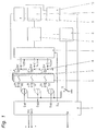
- a device for controlling a windshield wiper system Mainly consisting of a control stage 1, a clock generator unit consisting of a switch S and a clock generator 2, an I / U converter 3, a phase-selective rectifier 4 and an amplifier 5 with a low-pass filter, as well as a plurality of IR radiation transmitters SE, a radiation guide 6 and several Radiation receiver EM having optoelectronic device.
- Each IR radiation transmitter SE is preferably assigned an IR radiation receiver EM on the output side on the input side.
- Control stage 1 of the circuit arrangement is connected on the one hand via its inputs Vcc and GND to the voltage supply and on the other hand via its control output SA to the windshield wiper system of a motor vehicle. Furthermore, the transmission current Uo of the IR radiation transmitter SE is set via the control outputs S SE1 to S SEn of the control stage 1 and the conversion factor of the I / U converter 3 is set via the control output SK.
- the light emerging at the output of the optical path consists of a useful component (useful signal) originating from the beam transmitters SE and an interfering component resulting from the coupling in of external light sources (ambient light).
- the emitted by the radiation transmitters as IR-LED's SE is implemented by IR-trained as IR photodiodes and connected to a voltage source U1 radiation receivers EM and an associated resistor in an electrical quantity, which is then also from the useful part (useful signal) and the interference component put together.
- This electrical quantity generated is also dependent on the ambient temperature, since the efficiency of both the IR LEDs and the IR photodiodes is temperature-dependent. This leads to a falsification of the measurement result.
- the transmission current Uo of the IR LEDs is readjusted as a function of the temperature by control stage 1 so that the output variable becomes independent of the ambient temperature.
- the electrical variable prepared in this way is fed to the subsequent circuit parts which are required to separate the useful component from the interference component of the signal present as an electrical variable and thus to keep the signal / signal-to-noise ratio as large as possible.
- the alternating component of the electrical variable is converted into a voltage by the I / U converter 3 dynamically coupled to the receiving stage.
- the conversion factor can be specified externally via the control output SK, i.e. can be set.
- This I / U converter stage largely suppresses parts of static stray light sources.
- phase-selective rectifier 4 which works synchronously with the timing of the radiation transmitter SE designed as IR LEDs, generated by the switch S and clock generator 2.
- alternating interference signals that have a different frequency for clocking are suppressed.
- Another stage in signal processing is an amplifier 5 with low-pass behavior.
- the low-pass filter smooths out signal changes caused by extremely rapid changes in ambient light.
- the output signal (the output voltage) of this filter which acts as a low-pass filter, that is to say a correspondingly designed amplifier stage, ultimately represents the measure of the degree of wetting of the windshield 7. It is read in by a microprocessor belonging to the circuit arrangement and used to control the windshield wiper of a motor vehicle, the optoelectronic device is assigned to the wiping field of the windshield wiper.
- the microprocessor takes over the transmission current control of the radiation transmitters SE, which are designed as IR LEDs, and the Conversion factor control of the I / U converter 3, so that an automatic adaptation of the device to very different measuring conditions caused by different types of disks takes place.
- the adjustment is absolutely necessary, since the damping factor of the entire optical path depends very much on the respective lens type (clear glass, heat-insulating glass without band-stop filter, heat-insulating glass with band-stop filter).
- the circuit arrangement of the device is automatically moved into its optimal working area by this adaptation process.
- the setting values determined in this way are stored in a non-volatile memory of the circuit arrangement and are thus available as start values each time the device is activated without having to be readjusted.
- the transmission current control of the IR LEDs can be set separately in a range of 16 dB in 16 steps of 1 dB for each of the radiation transmitters SE designed as IR LEDs.
- the conversion factor control of the I / U converter 3 can be set in a range of 50 dB in 5 steps of 10 B. Thanks to the measures described above, a complete setting range of 65 dB can be covered in 1 dB steps for automatic adjustment of the device.
- Component tolerances can also be compensated for by overlapping the setting ranges.
- the overlap area is used in conjunction with the setting option, which is kept separate for the radiation transmitters SE, in order to carry out a sensitivity comparison between the optical links, each consisting of an IR LED and an IR photodiode, since only the sum signal of the optical links from the I / U - Converter 3 is implemented. This adjustment is necessary so that the sensitivity of the optical paths is identical to each other.
- the IR radiation transmitters SE of the optoelectronic device are advantageously operated in a pulsed manner with a current of a frequency> 2 KHz.
- This modulation produces a useful signal in the form of an alternating signal, which is fed to the IR radiation receiver EM via the radiation guide body 6 for evaluating the conditions present on the disk 7.
- the IR radiation receivers EM also receive the infrared light components of the ambient light. These infrared light components present themselves as a current superimposed on the useful signal. phase-selective rectifier 4, capacitive coupling and the like the superimposed current can be separated from the useful signal.
- phase-selective rectifier 4 capacitive coupling and the like the superimposed current can be separated from the useful signal.
- the IR radiation receivers EM have a non-linear characteristic. If the power of the IR radiation transmitter SE is kept constant, the non-linearity of the useful signal of the IR radiation receiver EM inevitably results, different ambient light conditions are present.
- the voltage drop across the working resistors 8 of the IR radiation receiver EM is used as a correction variable for the operation of the windshield wiper system.
- This correction e.g. also prevents the output voltage from slipping below a so-called interference level of the sensor device due to ambient light influences.
- the interference level represents the threshold above which signal changes are most likely to be evaluated as a coating on the disk 7.
- the linearization of the useful signal is achieved in detail because a first operational amplifier 9 is assigned to the IR radiation receiver EM for processing the voltage drop across the load resistor 8 to a correction quantity.
- a second operational amplifier 10 is present after the amplifier 5 with a low-pass filter, to which the useful signal present behind the amplifier 5 with a low-pass filter and on the other hand the prepared correction variable are supplied as input variables.
- the second operational amplifier 10 eliminates the changes in the useful signal caused by the ambient light by feeding in the correction variable, and the output voltage to be read into the control stage 1 is thus formed. An output voltage linearized by the correction variable is thus present behind the operational amplifier 10. Influences on the useful signal resulting from the ambient light are thus effectively eliminated.
Landscapes
- Engineering & Computer Science (AREA)
- Automation & Control Theory (AREA)
- Mechanical Engineering (AREA)
- Investigating Or Analysing Materials By Optical Means (AREA)
- Cleaning In General (AREA)
Claims (10)
- Dispositif de commande pour un système d'essuie-glaces avec un moteur d'entraînement pour au moins un bras d'essuie-glace pour le nettoyage de la surface extérieure d'une glace, avec un dispositif opto-électronique, qui est disposé sur la surface intérieure de la glace, dans la zone d'essuyage et comprend au moins un émetteur de rayons et au moins un capteur de rayons, et avec un agencement de connexion, qui est raccordé au dispositif opto-électronique et au moteur d'entraînement, les rayons échangés, de façon ryhtmée, entre l'émetteur et le capteur de rayons étant influencés par un liquide ou une substance solide se trouvant sur la glace et les signaux, lancés par le capteur de rayons étant, de ce fait, modifiés, en fonction du liquide ou de la substance qui couvre glace, et convertis en signaux de commande par l'agencement de connexion qui est composé essentiellement d'au moins un convertisseur I/U, qui amplifie la part de courant alternatif du signal du capteur, d'un redresseur sélectif de phases, qui redresse et filtre, à bande étroite, la part rythmée du signal de sortie du convertisseur I/U, et d'un filtre passe-bas, qui filtre les grandeurs parasites des éléments de connexion, ces signaux de commande influençant le fonctionnement du moteur d'entraînement,
caractérisé en ce que
l'agencement de connexion du système d'essuie-glaces présente une unité de commande (1), qui est pourvue d'une valeur de réglage de base déterminée par le dispositif opto-électronique en cas de propreté optimale de la glace (7) et représentant les conditions quasiment statiques des éléments de construction prévus pour la détection de substance se trouvant sur la vitre (7), cette unité de commande (1) étant coordonnée à au moins un convertisseur I/U (3) aux fins de réglage du facteur de conversion, et que la valeur de réglage de base est mémorisée dans une mémoire non volatile de l'agencement de connexion et prise comme valeur de départ pour toutes les mises en service du système d'essuie-glaces suivantes. - Dispositif de commande pour un système d'essuie-glaces selon la revendication 1,
caractérisé en ce que
l'unité de commande (1) est coordonnée aussi bien à, au moins, un convertisseur I/U (3), aux fins de réglage du facteur de conversion, qu'à, au moins, un émetteur de rayons (SE), aux fins de réglage du coucourant d'émission (Uo). - Dispositif de commande pour un système d'essuie-glaces selon l'une des revendications 1 ou 2,
caractérisé en ce que
une commande d'amplitude est prévue pour le réglage du courant d'émission. - Dispositif de commande pour un système d'essuie-glaces selon l'une des revendications 1 à 3,
caractérisé en ce que
le réglage du courant d'émission du/des émetteur/s de rayons (SE) peut être effectué dans une plage de 1 à 20 dB en échelons de 1 dB chacun et le réglage du facteur de conversion du convertisseur I/U (3) dans une plage de 10 à 80 dB en échelons de 10 dB chacun. - Dispositif de commande pour un système d'essuie-glaces selon l'une des revendications 1 à 4,
caractérisé en ce que
un réglage du courant d'émission, influençable séparément, est coordonné à chaque émetteur de rayons (SE) d'un dispositif opto-électronique composé de plusieurs émetteurs de rayons (SE) et de plusieurs capteurs de rayons (EM). - Dispositif de commande pour un système d'essuie-glaces selon l'une des revendications 1 à 5,
caractérisé en ce que
le/les émetteur/s de rayons (SE) consiste/nt essentiellement (chacun) en une DEL IR. - Dispositif de commande pour un système d'essuie-glaces selon l'une des revendications 1 à 6,
caractérisé en ce que
le/les capteur/s de rayons (EM) consiste/nt (chacun) essentiellement en une photodiode IR. - Dispositif de commande pour un système d'essuie-glaces selon la revendication 1,
caractérisé en ce que
au moins un capteur de rayons IR (EM) est équipé d'au moins une résistance de charge (8) et que la tension, tombant à la résistance de charge (8) en raison de la part de lumière ambiante est utilisée comme grandeur de correction pour le signal utile. - Dispositif de commande pour un système d'essuie-glaces selon la revendication 8,
caractérisé en ce que
la tension de sortie présente en aval de l'amplificateur (5) avec passe-bas, lue dans l'unité de commande (1) et représentant le signal utile, est soumise à la tension tombant à la résistance de charge (8) et traitée en grandeur de correction. - Dispositif de commande pour un système d'essuie-glaces selon la revendication 8,
caractérisé en ce que
un premier amplicateur opérationnel (9) est coordonné au capteur de rayons IR (EM) pour le traitement de la tension tombant à la résistance de charge (8) en tant que grandeur de correction et qu'en aval de l'amplificateur (5) avec passe-bas, un deuxième amplificateur opérationnel (10) est prévu, auquel, d'une part, le signal utile, présent derrière l'amplificateur (5) avec passe-bas, et, d'autre part, la grandeur de correction sont conduits, les modifications du signal utile provoquées par la lumière ambiante étant éliminées du deuxième amplificateur opérationnel (10) par la grandeur de correction, ce qui conduit à la formation de la tension de sortie qui est lue dans l'unité de commande (1).
Applications Claiming Priority (4)
| Application Number | Priority Date | Filing Date | Title |
|---|---|---|---|
| DE4120750A DE4120750A1 (de) | 1991-06-24 | 1991-06-24 | Einrichtung zur steuerung einer scheibenwischanlage |
| DE4120750 | 1991-06-24 | ||
| DE4217390A DE4217390C2 (de) | 1991-06-24 | 1992-05-26 | Einrichtung zur Steuerung einer Scheibenwischanlage |
| DE4217390 | 1992-05-26 |
Publications (2)
| Publication Number | Publication Date |
|---|---|
| EP0520302A1 EP0520302A1 (fr) | 1992-12-30 |
| EP0520302B1 true EP0520302B1 (fr) | 1994-12-07 |
Family
ID=25904824
Family Applications (1)
| Application Number | Title | Priority Date | Filing Date |
|---|---|---|---|
| EP92110175A Expired - Lifetime EP0520302B1 (fr) | 1991-06-24 | 1992-06-17 | Dispositif de commande d'un système d'essuie-glaces |
Country Status (3)
| Country | Link |
|---|---|
| EP (1) | EP0520302B1 (fr) |
| DE (2) | DE4217390C2 (fr) |
| ES (1) | ES2067982T3 (fr) |
Families Citing this family (6)
| Publication number | Priority date | Publication date | Assignee | Title |
|---|---|---|---|---|
| KR100302088B1 (ko) * | 1993-07-02 | 2001-12-28 | 게르트 라이메 | 배면방사요소의 변동검지장치 |
| US5726547A (en) * | 1993-07-02 | 1998-03-10 | Reime; Gerd | Windshield wiper arrangement including wiper control system |
| DE19643465C2 (de) † | 1996-10-22 | 1999-08-05 | Bosch Gmbh Robert | Steuervorrichtung für einen optischen Sensor, insbesondere einen Regensensor |
| DE19740364A1 (de) | 1997-09-13 | 1999-03-25 | Bosch Gmbh Robert | Vorrichtung und Verfahren zum Betreiben eines Regensensors |
| DE10214421B4 (de) * | 2002-03-30 | 2007-08-09 | Hella Kgaa Hueck & Co. | Verfahren zum Betreiben eines Regensensors, insbesondere für Kraftfahrzeuge |
| DE102007048858A1 (de) | 2007-10-11 | 2009-04-16 | Robert Bosch Gmbh | Verfahren zum Betreiben eines Regensensors insbesondere für Kraftfahrzeuge |
Family Cites Families (7)
| Publication number | Priority date | Publication date | Assignee | Title |
|---|---|---|---|---|
| DE3314770A1 (de) * | 1983-04-23 | 1984-10-31 | Sidler GmbH & Co, 7400 Tübingen | Einrichtung zum steuern eines scheibenwischermotors |
| DE3800327A1 (de) * | 1988-01-08 | 1989-07-27 | Bosch Gmbh Robert | Verfahren zum betreiben eines scheibenwischers und vorrichtung zur durchfuehrung des verfahrens |
| US4859867A (en) * | 1988-04-19 | 1989-08-22 | Donnelly Corporation | Windshield moisture sensing control circuit |
| DE3923281A1 (de) * | 1989-07-14 | 1991-01-24 | Bosch Gmbh Robert | Schmutzsensor fuer kraftfahrzeug-scheiben |
| US5059877A (en) * | 1989-12-22 | 1991-10-22 | Libbey-Owens-Ford Co. | Rain responsive windshield wiper control |
| DE4036407C2 (de) * | 1990-11-15 | 1994-06-01 | Telefunken Microelectron | Sensorsystem |
| DE4120750A1 (de) * | 1991-06-24 | 1993-01-07 | Kostal Leopold Gmbh & Co Kg | Einrichtung zur steuerung einer scheibenwischanlage |
-
1992
- 1992-05-26 DE DE4217390A patent/DE4217390C2/de not_active Expired - Fee Related
- 1992-06-17 DE DE59200899T patent/DE59200899D1/de not_active Expired - Fee Related
- 1992-06-17 ES ES92110175T patent/ES2067982T3/es not_active Expired - Lifetime
- 1992-06-17 EP EP92110175A patent/EP0520302B1/fr not_active Expired - Lifetime
Also Published As
| Publication number | Publication date |
|---|---|
| DE4217390A1 (de) | 1993-12-02 |
| ES2067982T3 (es) | 1995-04-01 |
| DE4217390C2 (de) | 1994-06-16 |
| DE59200899D1 (de) | 1995-01-19 |
| EP0520302A1 (fr) | 1992-12-30 |
Similar Documents
| Publication | Publication Date | Title |
|---|---|---|
| EP0682611B1 (fr) | Dispositif pour l'utilisation d'un detecteur de pluie | |
| EP0871579B2 (fr) | Dispositif de commande pour un capteur optique | |
| DE4318114C2 (de) | Sensoreinrichtung | |
| EP1012014B1 (fr) | Dispositif et procede pour le fonctionnement d'un detecteur de pluie | |
| EP2405283B1 (fr) | Agencement de mesure optoélectronique doté d'une source lumineuse de compensation | |
| DE69917559T2 (de) | Integrierter Selbsttest für Regensensoren | |
| DE3203091A1 (de) | Einrichtung zum erkennen von fremdstoffen auf einer scheibe | |
| EP0537471A1 (fr) | Procédé pour adapter la sensibilité de réaction d'un système détecteur de pluie à des conditions ambiantes et système détecteur avec un détecteur de pluie | |
| EP0520302B1 (fr) | Dispositif de commande d'un système d'essuie-glaces | |
| EP0988189B1 (fr) | Dispositif pour detecter le mouillage d'un vitre | |
| DE10117397A1 (de) | Sensor zur Detektion von Schmutz und/oder Feuchtigkeit auf einer Außenseite einer Scheibe | |
| EP1049609B1 (fr) | Dispositif pour la surveillance de l'etat d'une vitre de fenetre | |
| DE69936402T2 (de) | Feuchtigkeitssensor mit digitaler signalverarbeitungsfilterung | |
| DE4120750C2 (fr) | ||
| DE102020211101A1 (de) | Optischer Umgebungssensor sowie Fahrzeug | |
| DE10214421A1 (de) | Verfahren zum Betreiben eines Regensensors, insbesondere für Kraftfahrzeuge | |
| DE19504606A1 (de) | Optoelektronische Einrichtung | |
| DE4229491A1 (de) | Vorrichtung zur steuerung einer scheibenwischeranlage fuer kraftfahrzeuge | |
| EP1451614B1 (fr) | Procede de correction de lumiere parasite dans un ensemble capteur optique | |
| DE102007034606A1 (de) | System zum Erfassen optischer Signale mit einem Regensensor und Verfahren | |
| DE102007048858A1 (de) | Verfahren zum Betreiben eines Regensensors insbesondere für Kraftfahrzeuge | |
| DE10140265A1 (de) | Verfahren zur Kompensation des Temperatureinflusses auf die Sendeleistung einer Sende-LED und/oder die Empfindlichkeit einer Empfangsdiode | |
| EP1544068B1 (fr) | Unité de mesure pour un capteur de pluie pour détecter l'humidité sur une surface et un capteur d'humidité | |
| DE10041674A1 (de) | Verfahren und Vorrichtung zur automatischen Steuerung von Beleuchtungseinrichtungen | |
| EP1014568B1 (fr) | Méthode et dispositif de détection d'un signal reçu comportant du bruit |
Legal Events
| Date | Code | Title | Description |
|---|---|---|---|
| PUAI | Public reference made under article 153(3) epc to a published international application that has entered the european phase |
Free format text: ORIGINAL CODE: 0009012 |
|
| AK | Designated contracting states |
Kind code of ref document: A1 Designated state(s): DE ES FR GB IT SE |
|
| 17P | Request for examination filed |
Effective date: 19930119 |
|
| 17Q | First examination report despatched |
Effective date: 19940408 |
|
| GRAA | (expected) grant |
Free format text: ORIGINAL CODE: 0009210 |
|
| AK | Designated contracting states |
Kind code of ref document: B1 Designated state(s): DE ES FR GB IT SE |
|
| REF | Corresponds to: |
Ref document number: 59200899 Country of ref document: DE Date of ref document: 19950119 |
|
| ITF | It: translation for a ep patent filed | ||
| GBT | Gb: translation of ep patent filed (gb section 77(6)(a)/1977) |
Effective date: 19950217 |
|
| ET | Fr: translation filed | ||
| REG | Reference to a national code |
Ref country code: ES Ref legal event code: FG2A Ref document number: 2067982 Country of ref document: ES Kind code of ref document: T3 |
|
| PLBE | No opposition filed within time limit |
Free format text: ORIGINAL CODE: 0009261 |
|
| STAA | Information on the status of an ep patent application or granted ep patent |
Free format text: STATUS: NO OPPOSITION FILED WITHIN TIME LIMIT |
|
| 26N | No opposition filed | ||
| PGFP | Annual fee paid to national office [announced via postgrant information from national office to epo] |
Ref country code: FR Payment date: 19981009 Year of fee payment: 7 |
|
| PG25 | Lapsed in a contracting state [announced via postgrant information from national office to epo] |
Ref country code: FR Free format text: THE PATENT HAS BEEN ANNULLED BY A DECISION OF A NATIONAL AUTHORITY Effective date: 19990630 |
|
| REG | Reference to a national code |
Ref country code: FR Ref legal event code: ST |
|
| REG | Reference to a national code |
Ref country code: GB Ref legal event code: IF02 |
|
| PGFP | Annual fee paid to national office [announced via postgrant information from national office to epo] |
Ref country code: SE Payment date: 20030610 Year of fee payment: 12 |
|
| PGFP | Annual fee paid to national office [announced via postgrant information from national office to epo] |
Ref country code: GB Payment date: 20040615 Year of fee payment: 13 |
|
| PG25 | Lapsed in a contracting state [announced via postgrant information from national office to epo] |
Ref country code: SE Free format text: LAPSE BECAUSE OF NON-PAYMENT OF DUE FEES Effective date: 20040618 |
|
| PGFP | Annual fee paid to national office [announced via postgrant information from national office to epo] |
Ref country code: ES Payment date: 20040618 Year of fee payment: 13 |
|
| EUG | Se: european patent has lapsed | ||
| EUG | Se: european patent has lapsed | ||
| PG25 | Lapsed in a contracting state [announced via postgrant information from national office to epo] |
Ref country code: IT Free format text: LAPSE BECAUSE OF NON-PAYMENT OF DUE FEES;WARNING: LAPSES OF ITALIAN PATENTS WITH EFFECTIVE DATE BEFORE 2007 MAY HAVE OCCURRED AT ANY TIME BEFORE 2007. THE CORRECT EFFECTIVE DATE MAY BE DIFFERENT FROM THE ONE RECORDED. Effective date: 20050617 Ref country code: GB Free format text: LAPSE BECAUSE OF NON-PAYMENT OF DUE FEES Effective date: 20050617 |
|
| PG25 | Lapsed in a contracting state [announced via postgrant information from national office to epo] |
Ref country code: ES Free format text: LAPSE BECAUSE OF NON-PAYMENT OF DUE FEES Effective date: 20050618 |
|
| GBPC | Gb: european patent ceased through non-payment of renewal fee |
Effective date: 20050617 |
|
| REG | Reference to a national code |
Ref country code: ES Ref legal event code: FD2A Effective date: 20050618 |
|
| PGFP | Annual fee paid to national office [announced via postgrant information from national office to epo] |
Ref country code: DE Payment date: 20080510 Year of fee payment: 17 |
|
| PG25 | Lapsed in a contracting state [announced via postgrant information from national office to epo] |
Ref country code: DE Free format text: LAPSE BECAUSE OF NON-PAYMENT OF DUE FEES Effective date: 20100101 |