EP0520306B2 - Mehrstrahl-Wasserzähler - Google Patents
Mehrstrahl-Wasserzähler Download PDFInfo
- Publication number
- EP0520306B2 EP0520306B2 EP19920110186 EP92110186A EP0520306B2 EP 0520306 B2 EP0520306 B2 EP 0520306B2 EP 19920110186 EP19920110186 EP 19920110186 EP 92110186 A EP92110186 A EP 92110186A EP 0520306 B2 EP0520306 B2 EP 0520306B2
- Authority
- EP
- European Patent Office
- Prior art keywords
- impeller
- cartridge
- water meter
- compartment
- water
- Prior art date
- Legal status (The legal status is an assumption and is not a legal conclusion. Google has not performed a legal analysis and makes no representation as to the accuracy of the status listed.)
- Expired - Lifetime
Links
- XLYOFNOQVPJJNP-UHFFFAOYSA-N water Substances O XLYOFNOQVPJJNP-UHFFFAOYSA-N 0.000 title claims description 50
- 229920003023 plastic Polymers 0.000 claims description 9
- 239000004033 plastic Substances 0.000 claims description 8
- 230000007246 mechanism Effects 0.000 claims description 7
- 230000001681 protective effect Effects 0.000 claims description 7
- 230000001066 destructive effect Effects 0.000 claims description 3
- 230000009467 reduction Effects 0.000 claims description 3
- 239000000463 material Substances 0.000 claims description 2
- 210000004907 gland Anatomy 0.000 claims 2
- 239000011521 glass Substances 0.000 claims 1
- 229910052751 metal Inorganic materials 0.000 description 5
- 239000002184 metal Substances 0.000 description 5
- 238000010276 construction Methods 0.000 description 3
- 230000006378 damage Effects 0.000 description 3
- 238000009434 installation Methods 0.000 description 3
- 238000005259 measurement Methods 0.000 description 3
- 230000005540 biological transmission Effects 0.000 description 2
- 230000008878 coupling Effects 0.000 description 2
- 238000010168 coupling process Methods 0.000 description 2
- 238000005859 coupling reaction Methods 0.000 description 2
- 229910001369 Brass Inorganic materials 0.000 description 1
- 230000008901 benefit Effects 0.000 description 1
- 239000010951 brass Substances 0.000 description 1
- 230000001419 dependent effect Effects 0.000 description 1
- 230000000694 effects Effects 0.000 description 1
- 229910001385 heavy metal Inorganic materials 0.000 description 1
- 239000012535 impurity Substances 0.000 description 1
- 238000000034 method Methods 0.000 description 1
- 239000002245 particle Substances 0.000 description 1
- 238000010992 reflux Methods 0.000 description 1
- 230000000630 rising effect Effects 0.000 description 1
- 238000005096 rolling process Methods 0.000 description 1
- 238000000926 separation method Methods 0.000 description 1
- 239000007787 solid Substances 0.000 description 1
- 238000003466 welding Methods 0.000 description 1
Images



Classifications
-
- G—PHYSICS
- G01—MEASURING; TESTING
- G01F—MEASURING VOLUME, VOLUME FLOW, MASS FLOW OR LIQUID LEVEL; METERING BY VOLUME
- G01F1/00—Measuring the volume flow or mass flow of fluid or fluent solid material wherein the fluid passes through a meter in a continuous flow
- G01F1/05—Measuring the volume flow or mass flow of fluid or fluent solid material wherein the fluid passes through a meter in a continuous flow by using mechanical effects
- G01F1/06—Measuring the volume flow or mass flow of fluid or fluent solid material wherein the fluid passes through a meter in a continuous flow by using mechanical effects using rotating vanes with tangential admission
-
- G—PHYSICS
- G01—MEASURING; TESTING
- G01F—MEASURING VOLUME, VOLUME FLOW, MASS FLOW OR LIQUID LEVEL; METERING BY VOLUME
- G01F15/00—Details of, or accessories for, apparatus of groups G01F1/00 - G01F13/00 insofar as such details or appliances are not adapted to particular types of such apparatus
- G01F15/12—Cleaning arrangements; Filters
- G01F15/125—Filters
-
- G—PHYSICS
- G01—MEASURING; TESTING
- G01F—MEASURING VOLUME, VOLUME FLOW, MASS FLOW OR LIQUID LEVEL; METERING BY VOLUME
- G01F15/00—Details of, or accessories for, apparatus of groups G01F1/00 - G01F13/00 insofar as such details or appliances are not adapted to particular types of such apparatus
- G01F15/14—Casings, e.g. of special material
Definitions
- the invention relates to multi-jet water meter according to Claim 1.
- Water meters with measuring inserts that are independent can be adjusted from the metallic meter housing and when installed in any housing their correct To maintain adjustment are, for example known from DE-A-22 05 154, DE-A-29 23 628, DE-A-23 37 465, DE-A-23 38 327, DE-B-12 40 677, DE-B-23 39 897, DE-B-11 60 200, DE-B-10 19 835 or DE-U-73 11,732.
- the complete usually made of cast brass existing meter housing with the old one Replaced measuring insert and returned to the factory.
- the old measuring insert expanded, the metal housing cleaned, a new one Measuring insert inserted, the complete unit is adjusted and finally the credential stamp attached.
- This procedure is not only the worn Measuring insert, but also the heavy metal housing transported, resulting in significant weight and Transport costs caused.
- the water meter according to the invention has as essential element a measuring insert with a Plastic housing, can be used in the actual metallic Meter housing.
- the plastic housing, cartridge called, contains all the components for a Calibration are required. The use ensures this also functions of the previous meter housing, For example, the pressure-tight closure to the outside, the free view of the measuring mechanism etc.
- the cartridge housing is at least made two parts, the cartridge base and the cartridge shell. Both are non-destructive not to be solved connection connected. This can for example be a locking connection with a circumferential locking groove and detent spring.
- the wing cup is in the present Case of a wing cup base and a separately made of this wing cup top, the with the help of adjusting pins and corresponding adjustment holes in the facing divisions be installed at right angles. With correct dimensioning the adjusting pin in relation to the Justierbohrungen it is possible to lower part and upper part of the wing cup connect by welding together.
- the tangential inflow channels are exclusively in the wall of the wing cup top intended. Preferably, it is twice three inflow channels facing each other are arranged.
- For influencing the flow characteristics are hydraulic installations in the form of radial Staurippen, a circumferential stowage edge and Storage spaces provided in the inner wall of the wing cup.
- the inflow channels In front of the inflow channels with a is arranged at a certain distance to these, the inflow channels partially covered and roughly parabolic has curved inner surface.
- Water meters come with a hinged protective cover equipped with the transparent top in front Protects dirt and damage.
- This Folding protective cover is in the present invention directly on the top of the cartridge shell hinged, preferably by means of a hinge pin, which is inserted in a blind hole. Thanks this type of mounting the protective cover is not visible To solve the destruction. This in turn makes it possible, attestation stamp, manufacturer's mark etc. directly in the protective cover.
- the meter housing are made very simple can. It consists of a base with a coaxial Arrangement of water inflow and outflow and a bonnet as a head cap. The seal against the leakage of water by only three O-rings, one for the seal between Housing base and housing top, one for the Seal between housing base and cartridge and one for the seal between the cartridge and Head screw is responsible.
- a Non-return check valve can be used, and advantageously directly under the cartridge. So this check valve during assembly of the Measuring cartridge used and when replacing the Measuring cartridge also be replaced.
- annular gaps for example, there where in Nrustauerrtyp the impeller shaft through the wing cup or passes through the counter, or where the measuring cartridge received in the lower housing part becomes. These annular gaps are supposed to be a water flow prevent if possible, without the pressure equalization to hinder.
- the cartridge lower part slightly conically tapered towards the bottom. This leaves between the housing and the Measuring cartridge a conical gap, the water exchange and thus minimizes the deposits, so that a later replacement or replacement of the measuring cartridge without problems is possible.
- the measuring insert not only as Nrustauerr, but also designed as a dry runner can be.
- the wing cup is top with a pressure-resistant metal plate supported, the transmission the speed of the impeller on the counter takes place in a known manner by means of magnetic coupling.
- Fig. 1 shows a longitudinal section through a measuring cartridge 3 of the wet runner type.
- An adjustment cam 35 in a corresponding Groove represents the correct angular position of Cartridge base 30 and cartridge top 31 safe.
- a protective cover 32 On the outside of the cartridge shell 31 is a protective cover 32 by means of a hinge pin 33 in attached to a blind hole hinged. Thanks to this unsolvable Fastening the hinged lid 32 it is possible Manufacturer's mark, certification stamp 32 'etc. to install on the inside of the hinged lid 32.
- the cartridge base 30 has a bottom, the outer annular surface 38 is formed as a dirt sieve is.
- the sieve openings are slightly conical. Thereby the water is accelerated as it passes through; of the resulting pressure drop leaves any impurities fail before entering the inside of the measuring cartridge 3 arrive.
- the lower edge of the cartridge base 30 is tapered stepwise and provided with adjusting socks 39, the angular positioning of the measuring cartridge 3 in the meter housing 1.
- a wing cup consisting of wellgelbecherunterteil 40 and sash cup top 60, in which in itself a known manner, an impeller 42 on a bearing tip 41 easily rotatable.
- An impeller shaft 43 is through the wing cup top 60 passes and drives a seated in a measuring cup 70 reduction gear 75 on.
- annular gaps 67 and 67.1 are formed, seal the labyrinthine against water currents, without the entry of water into the measuring cup to prevent. This measure prevents harmful Deposits in the counter from the flowing through Water.
- the measuring cup 70 is formed substantially through a cylindrical plastic ring, put on the sash cup top 60 and covered by above a dial 72. There are pointers 73 and number wheels 74 arranged so that they pass through the cartridge shell 31 are easily read through.
- Fig. 1 further reveals is on the wing cup top 60 outside and at a distance from the tangential inflow channels 61 an apron 65th formed.
- Whose the inflow channels 61 facing Inner side is approximately parabolic curved. Thereby is the deflection of the first vertically rising Measuring water in the horizontal favorably influenced.
- the lower one sits Edge of the skirt 65 on a step 36 on the inside of the cartridge base 30, whereby the wing cup 40, 60 is positioned correctly.
- Adjustment socks 66 on the underside of the skirt 65 ensure the correct angular position.
- the wellgelbecherunterteil 40 has below two bypass openings 44, with which the ad overall can be moved to minus or plus. To the Amount of passing through these bypass openings Being able to adjust water is central Water outlet in the bottom of the cartridge base 30 an adjusting ring 50 is inserted. Its top edge 51 is formed twice ramp-shaped and closes depending on the angular position of the adjusting ring 50 a more or less large part of the adjustment openings 44th
- Wing cup bottom part 40 and top 60 are based on Figs. 3 and 4 are shown in more detail.
- Fig. 3 shows a plan view of the wellgelbecherunterteil 40, wherein a part of the sash cup top 60th is visible on average.
- the impeller 42 and its cut shaft 43 In the wellgelbecherunterteil 40 can be seen radial baffles 45, which in the area the central water outlet 46 made obliquely are to enter in case of a water backflow Backward running of the impeller 42 to effect.
- the Staurippen 45 serve to the flow of water so influence that the measurement accuracy is improved.
- Fig. 3 also shows adjusting pin 47 on copebelcherunterteil 40, in corresponding holes in the sash cup top 60 are used. This is the right angle Assembly of the wing cup 40, 60 guaranteed.
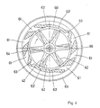
- Fig. 4 shows the view from below into the wing cup top 60. You can also see on the ceiling of the wing cup top 60 radial storage ribs 62 and a circumferential traffic jam 64.
- the apron 65 with its approximately parabolic curved Inside, the jammed edge 64, the storage ribs 62, 45 and the storage spaces 63 are responsible for that the counter shown the water with accuracy the metrological class C measures.
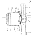
- Fig. 5 shows a longitudinal section through the meter housing 1 with mounted measuring cartridge 3 as shown in FIGS. 1 to 4.
- the meter housing 1 has a water inlet nozzle 11 and a water outlet 12. The separation between water inlet and outlet takes place through an annular surface 13 on which the O-ring 14 in the bottom the measuring cartridge 3 is seated.
- the measuring cartridge 3 is inside the meter housing 1 fixed by means of the head screw 15 and sealed with O-rings 16 and 17.
- a seal 18 protects against unauthorized manipulation.
- the cartridge base 30 is toward the bottom 38 slightly conically tapered. This leaves a gap 19 between measuring cartridge 3 and meter housing 1, in the dirt particles can be deposited from the water, without hindering the removal of the measuring cartridge 3. Through so-called annular gaps between measuring cartridge 3 and meter housing 1 or head screw 15 is otherwise ensured that no possible Water can flow through these housing areas.
- Fig. 5 can in the meter housing 1 directly under the measuring cartridge 3 a Water reflux preventing check valve 20 with Valve seat 21 are used.
- the measuring cartridge 3 replaced on site, where as already mentioned only the head screw 15 is released while the lower housing part 1 remains installed in the line, can also Check valve 20, 21 easily replaced from above become.
- Fig. 6 shows a longitudinal section through a meter housing 1, in which a measuring cartridge 3 of the dry-runner type is used.
- a measuring cartridge 3 of the dry-runner type is used.
- the impeller on the measuring mechanism is a magnetic coupling 601 provided.
- the fitters of the water supply companies just have to essentially this out Plastic existing, lightweight measuring cartridge 3 with it to lead.
- the old measuring cartridge 3 removed, optionally also the check valve 20, any Deposits in meter housing 1 are wiped out, a new measuring cartridge 3 and possibly a new one Check valve 20 used, the Koptverschraubung 15 screwed back to stop and the security seal 18 attached.
- the old measuring cartouche does not have to go back to the factory, but is disposed of as plastic scrap in accordance with regulations.
Landscapes
- Physics & Mathematics (AREA)
- Fluid Mechanics (AREA)
- General Physics & Mathematics (AREA)
- Measuring Volume Flow (AREA)
Description
- Fig. 1
- einen Längsschnitt durch eine komplette Naßläufer-Meßkartusche,
- Fig. 2
- eine Draufsicht auf die Meßkartusche der Fig. 1,
- Fig. 3
- einen Schnitt durch den Flügelbecher der Fig. 1 gemäß der Linie III-III,
- Fig. 4
- einen Schnitt durch den Flügelbecher der Fig. 1 gemäß der Linie IV-IV,
- Fig. 5
- einen Längsschnitt durch einen kompletten Zähler mit eingesetzter, teilweise aufgebrochen darstellter Meßkartusche nach Fig. 1 und
- Fig. 6
- einen Längsschnitt durch einen kompletten Zähler mit eingesetzter, teilweise aufgebrochen dargestellter Meßkartusche vom Trokkenläufer-Typ.
Claims (13)
- Mehrstrahl-Wasserzähler mit einem Zählergehäuse (1) mit Kopfverschraubung (15) und mit einer Meßkartusche (3), im wesentlichen bestehend aus Kunststoff,auswechselbar einsetzbar in das Zählergehäuse (1),umfassend einen zweiteiligen Flügelbecher (40, 60)mit einem Flügelrad (42) mit senkrechter Welle (43),mit mehreren tangential gerichteten Einströmkanälen (61),mit einer bodenseitigen Ausströmöffnung (46),mit hydraulisch aktiven Einbauten (45, 62, 63, 64)und mit einer den Flügelbecher (40, 60) mit Abstand umgebenden, die Einströmkanäle (61) teilweise überdeckenden Schürze (65)und weiterhin umfassend einen Werkbecher (70)mit Reduziergetriebe (75)mit Zifferblatt (72)und mit Zeigern (73) und Rollenzählwerk (74); unddas Kartuschen-Oberteil (31) der Meßkartusche (3) ist als transparentes Schauglas ausgebildet,das Kartuschen-Unterteil (30) ist becherartig geformt,der Boden des Kartuschen-Unterteils besitzteine als Schmutzsieb (38) ausgebildete Ringfläche für den Wasserzulauf,eine zentrale Öffnung für den Wasserablauf (46),dazwischen eine Ringnabe (37) zur Abstützung auf dem Zählergehäuse (1)und ist federnd nachgiebig,Kartuschen-Oberteil (31) und Kartuschen-Unterteil (30) sind durch eine zerstörungsfrei nicht zu lösende Verbindung (34) miteinander verbunden,der Flügelbecher (40, 60) besteht aus einem Flügelbecher-Unterteil (40) und einem Flügelbecher-Oberteil (60),das Fügelbecher-Unterteil (40) besitztbodenseitig radiale Staurippen (45)eine zentrale Öffnung (46) für den Wasserablauf,das Flügelbecher-Oberteil (60) besitztdie tangentialen Einströmkanäle (61),deckelseitig radiale Staurippen (62),eine ringförmig umlaufende Staukante (64)und wenigstens eine zum Flügelrad (42) hin offene Staukammer (63, 63'),eine Bypaß-Öffnung (44) zwischen Wasserzu- und -ablaufseite ist im Becher-Unterteil (40) angeordnet,der Werkbecher (70) besteht aus einem Zylinderabschnitt,auf den Flügelbecher (40, 60) aufgesetztund oben durch das Zifferblatt (72) abgedeckt,das Kartuschen-Unterteil (30) besitzt innen eine Stufe (36), auf der sich die angeformte Schürze (65) abstützt.
- Wasserzähler nach Anspruch 1, gekennzeichnet durch das Merkmal:die Verbindung (34) zwischen Kartuschen-Unterteil (30) und Kartuschen-Oberteil (31) umfaßt eine umlaufende Rastnut und Rastfeder.
- Wasserzähler nach Anspruch 1 oder 2, gekennzeichnet durch das Merkmal:das Kartuschen-Oberteil (31) besitzt einen Zentriernocken (35), das Kartuschen-Unterteil (30) eine entsprechende Zentriernut zur gegenseitig winkelrichtigen Montage.
- Wasserzähler nach einem der Ansprüche 1 bis 3, gekennzeichnet durch die Merkmale:das Kartuschen-Oberteil (31) trägt auf seiner Oberseite einen klappbaren Schutzdeckel (32),der Schutzdeckel (32) ist mittels Gelenkstift (33), eingesetzt in eine Sackbohrung, angelenkt und zerstörungsfrei nicht zu lösen.
- Wasserzähler nach einem der Ansprüche 1 bis 4, gekennzeichnet durch die Merkmale:in die zentrale bodenseitige Öffnung des Kartuschen-Unterteils (30) ist ein Justierring (50) eingesetzt,dessen Kante (51) ist rampenförmig abgeschrägt und verschließt die Bypaß-Öffnung (44) mehr oder weniger.
- Wasserzähler nach einem der Ansprüche 1 bis 5, gekennzeichnet durch die Merkmale:die Kopfverschraubung (15) besitzt eine umlaufende Nut (15.1) zur Aufnahme eines zwischen der Kopfverschraubung (15) und dem Zählergehäuse (1) abdichtenden O-Rings (16).die Ringnabe (37) besitzt eine umlaufende Nut zur Aufnahme eines gegen das Zählergehäuse (1) abdichtenden O-Rings (14).das Zählergehäuse (1) besitzt einen ringförmigen Absatz zur Abdichtung zwischen Zählergehäuse (1) und Kopfverschraubung (15) mittels O-Ring (17).
- Wasserzähler nach einem der Ansprüche 1 bis 6, gekennzeichnet durch das Merkmal:die Außenwand des Kartuschen-Unterteils (30) trägt Zentriernuten (39) zur winkelrichtigen Positionierung der Meßkartusche (3) im Zählergehäuse (1).
- Wasserzähler nach einem der Ansprüche 1 bis 7, gekennzeichnet durch das Merkmal:das Kartuschen-Unterteil (30) ist zum Boden hin leicht konisch verjüngt.
- Wasserzähler nach einem der Ansprüche 1 bis 8, gekennzeichnet durch das Merkmal:die den Einströmöffnungen (61) zugewandte Innenfläche der Schürze (65) ist etwa parabolisch gekrümmt.
- Wasserzähler nach einem der Ansprüche 1 bis 9, gekennzeichnet durch das Merkmal:Flügelbecher-Unterteil (40) und Flügelbecher-Oberteil (60) besitzen in den einander zugekehrten Trennflächen Justierzapfen (47) und -bohrungen.
- Wasserzähler nach einem der Ansprüche 1 bis 10, gekennzeichnet durch das Merkmal:in das Zählergehäuse (1) ist ein den Rückfluß verhinderndes Ventil (20, 21) zentral eingesetzt, vorzugsweise direkt unter der Meßkartusche (3).
- Wasserzähler nach einem der Ansprüche 1 bis 11, gekennzeichnet durch das Merkmal:zwischen Meßraum und Zählwerkraum ist eine Labyrinthstopfbüchse angeordnet, die durch glatte Ringspalten (67) zwischen Flügelradwelle 43 und Flügelbecher-Oberteil 60 und Ringspalten 67.1 zwischen Flügelradwelle 43 und Zählwerkunterplatine (10) begrenzt ist.
- Wasserzähler nach einem der Ansprüche 1 bis 12, gekennzeichnet durch das Merkmal:der Flügelbecher (40, 60) ist oberseitig mit einer druckfesten Platte (600) abgedichtet;eine Magnetkupplung (601) überträgt die Drehungen des Flügelrades (42) zum Reduziergetriebe (75).
Applications Claiming Priority (2)
| Application Number | Priority Date | Filing Date | Title |
|---|---|---|---|
| DE4121056 | 1991-06-26 | ||
| DE19914121056 DE4121056C2 (de) | 1991-06-26 | 1991-06-26 | Mehrstrahl-Wasserzähler |
Publications (4)
| Publication Number | Publication Date |
|---|---|
| EP0520306A2 EP0520306A2 (de) | 1992-12-30 |
| EP0520306A3 EP0520306A3 (en) | 1995-03-22 |
| EP0520306B1 EP0520306B1 (de) | 1997-12-03 |
| EP0520306B2 true EP0520306B2 (de) | 2005-11-02 |
Family
ID=6434759
Family Applications (1)
| Application Number | Title | Priority Date | Filing Date |
|---|---|---|---|
| EP19920110186 Expired - Lifetime EP0520306B2 (de) | 1991-06-26 | 1992-06-17 | Mehrstrahl-Wasserzähler |
Country Status (4)
| Country | Link |
|---|---|
| EP (1) | EP0520306B2 (de) |
| DE (1) | DE4121056C2 (de) |
| ES (1) | ES2111015T3 (de) |
| GR (1) | GR3026005T3 (de) |
Families Citing this family (26)
| Publication number | Priority date | Publication date | Assignee | Title |
|---|---|---|---|---|
| DE9314745U1 (de) * | 1993-09-29 | 1993-12-09 | SaMeCo Meßtechnik GmbH, 10627 Berlin | Meßkapselzähler |
| DE4440683C2 (de) * | 1994-11-15 | 1997-09-25 | Wehrle E Gmbh | Meßeinsatz für Flüssigkeitszähler |
| DE19816322C2 (de) * | 1998-04-11 | 2003-03-06 | Wallisellen Ag Armaturen | Wasserzähler-Anschluß und Wasserzähler-Einheit |
| FR2789173B1 (fr) | 1999-02-02 | 2001-03-02 | Production De Procedes De Comp | Compteur de liquide a jet unique |
| DE19944087C1 (de) * | 1999-09-15 | 2001-02-08 | Spanner Pollux Gmbh | Wasserzähler |
| DE29920282U1 (de) * | 1999-11-18 | 2001-03-29 | Spanner-Pollux Gmbh, 67063 Ludwigshafen | Wasserzähler |
| DE19959997C2 (de) * | 1999-12-13 | 2001-11-08 | Spanner Pollux Gmbh | Wasserzähler |
| DE10019529C1 (de) * | 2000-04-20 | 2001-11-15 | Spanner Pollux Gmbh | Wasserzähler |
| DE10106465B4 (de) * | 2001-02-13 | 2015-12-03 | Elster Messtechnik Gmbh | Meßeinsatz für einen Volumenzähler für Flüssigkeiten und Verfahren zum Messen eines Flüssigkeitsvolumens mit dem Meßeinsatz |
| DE10106466B4 (de) * | 2001-02-13 | 2011-04-14 | Elster Messtechnik Gmbh | Meßeinsatz für einen Volumenzähler für Flüssigkeiten |
| DE20110370U1 (de) * | 2001-06-22 | 2001-09-13 | E. Wehrle GmbH, 78120 Furtwangen | Wassermeßgerät mit Kunststoffgehäuse |
| DE10229795B4 (de) * | 2002-07-03 | 2006-08-17 | M & Fc Holding Llc | Flüssigkeitszähler mit einem Gehäuse aus Kunststoff |
| DE10229794C1 (de) * | 2002-07-03 | 2003-12-11 | Invensys Metering Systems Gmbh | Einstrahlzähler für Flüssigkeiten |
| DE10309665B3 (de) * | 2003-03-06 | 2004-06-17 | Hydrometer Gmbh | Messeinsatz für einen Flügelradzähler mit verbesserter Fehlerkurve |
| DE102004012414C5 (de) * | 2004-03-13 | 2010-12-16 | Hydrometer Gmbh | Messeinsatz und Fluidzähler |
| DE102004055816B4 (de) * | 2004-11-18 | 2006-11-16 | Hydrometer Gmbh | Fluidzähler |
| DE102005023826B4 (de) * | 2005-05-24 | 2007-10-31 | Hydrometer Gmbh | Messeinsatz und Flüssigkeitszähler |
| DE102006002519A1 (de) * | 2006-01-13 | 2007-07-26 | Minol Messtechnik W. Lehmann Gmbh & Co. Kg | Messkapsel für Flüssigkeitszähler und Flüssigkeitszähler |
| DE102006030669B4 (de) * | 2006-07-04 | 2014-09-18 | M & Fc Holding Llc | Messeinsatz für Flüssigkeitszähler |
| DE102006043937B4 (de) * | 2006-09-14 | 2008-09-18 | Hydrometer Gmbh | Zählergehäuse zum Einsetzen in eine Rohrleitung, insbesondere Wasserzählergehäuse, ein solches Zählergehäuse umfassender Zähler, sowie Verfahren zur Herstellung eines solchen Zählergehäuses |
| DE102007002685A1 (de) * | 2007-01-18 | 2008-07-31 | Techem Energy Services Gmbh | Anschlussgehäuse und Verbrauchsmessgerät |
| DE102009018060B4 (de) | 2009-04-21 | 2011-01-27 | Hydrometer Gmbh | Zähler, insbesondere Wasserzähler |
| DE102009030828B3 (de) * | 2009-06-26 | 2010-11-25 | Qundis Gmbh | Wasser-/Wärmezähler |
| DE102012112872A1 (de) * | 2012-12-21 | 2014-07-10 | Conti Temic Microelectronic Gmbh | Sensoranordnung und Verfahren zur Herstellung einer Sensoranordnung |
| DE102014216553B3 (de) | 2014-08-20 | 2016-02-11 | Landis+Gyr Gmbh | Durchflussmesser mit einem in ein Gehäuse eingesetzten Messeinsatz |
| EP4617629A1 (de) * | 2024-03-11 | 2025-09-17 | Engelmann Sensor GmbH | Adapterbauteil, durchflussmengenmesser und herstellungsverfahren für ein adapterbauteil |
Family Cites Families (12)
| Publication number | Priority date | Publication date | Assignee | Title |
|---|---|---|---|---|
| DE204165C (de) * | 1907-05-18 | |||
| DE2337465C2 (de) * | 1973-07-24 | 1987-05-07 | E. Wehrle Gmbh, 7743 Furtwangen | Flüssigkeitszähler |
| DE2363909C2 (de) * | 1973-12-21 | 1986-10-16 | Elster AG, Meß- und Regeltechnik, 6700 Ludwigshafen | Austauschbarer Meßeinsatz für Wasserzähler |
| DE2365026A1 (de) * | 1973-12-28 | 1975-07-10 | Elster Ag | Fluegelrad-wasserzaehler |
| CH597592A5 (de) * | 1976-05-18 | 1978-04-14 | Gas & Wassermesserfab Ag | |
| DE2937013A1 (de) * | 1979-09-13 | 1981-04-09 | Schöll, Günter, Prof. Dr.-Ing., 7441 Wolfschlugen | Armatur zur mengenregelung und mengenmessung von fluessigkeiten |
| US4430901A (en) * | 1980-07-24 | 1984-02-14 | Brown Boveri Kent Limited | Fluid meter |
| DE3247376C2 (de) * | 1982-12-22 | 1986-02-13 | Wassermesserfabrik Andrae Gmbh + Co, 7250 Leonberg | Durchflussmengenzähler für Flüssigkeiten |
| FR2581755B1 (fr) * | 1985-05-09 | 1987-06-12 | Sato Electronique Sa | Debitmetre a turbine pour fluides |
| DE3814791A1 (de) * | 1988-04-30 | 1989-11-16 | Bopp & Reuther Gmbh | Fluegelradzaehler |
| DE3909722A1 (de) * | 1989-03-23 | 1990-09-27 | Hydrometer Gmbh | Fluegelradzaehler |
| FR2646271B3 (fr) * | 1989-04-21 | 1991-05-31 | Sappel Sa | Compteur a protection transparente |
-
1991
- 1991-06-26 DE DE19914121056 patent/DE4121056C2/de not_active Revoked
-
1992
- 1992-06-17 EP EP19920110186 patent/EP0520306B2/de not_active Expired - Lifetime
- 1992-06-17 ES ES92110186T patent/ES2111015T3/es not_active Expired - Lifetime
-
1998
- 1998-01-28 GR GR980400175T patent/GR3026005T3/el unknown
Also Published As
| Publication number | Publication date |
|---|---|
| DE4121056A1 (de) | 1993-01-07 |
| ES2111015T3 (es) | 1998-03-01 |
| EP0520306A3 (en) | 1995-03-22 |
| GR3026005T3 (en) | 1998-04-30 |
| EP0520306A2 (de) | 1992-12-30 |
| DE4121056C2 (de) | 1994-09-01 |
| EP0520306B1 (de) | 1997-12-03 |
Similar Documents
| Publication | Publication Date | Title |
|---|---|---|
| EP0520306B2 (de) | Mehrstrahl-Wasserzähler | |
| DE3737036C2 (de) | ||
| DE2349131A1 (de) | Auswechselbares sitzventil | |
| DE4325256A1 (de) | Mischventil mit Druckausgleich | |
| EP0531318B1 (de) | Sanitärarmatur mit schwenkbarem auslaufarm | |
| DE19728562C2 (de) | Regelbarer Kugelhahn | |
| EP0874226B1 (de) | Verbundwasserzähler | |
| EP2108748B1 (de) | Sanitärarmatur | |
| DE3732703C2 (de) | ||
| DE102007007408A1 (de) | Wasserzulaufarmatur | |
| DE3242763A1 (de) | Adapter fuer einen ventilzaehler | |
| DE202004005030U1 (de) | Zweiteiliger Vorreiberverschluss | |
| DE1122788B (de) | Hahn mit am Kueken beweglich gelagertem Abschlussteil und im Gehaeuse verschiebbar gelagertem Dichtsitzring | |
| DE102012102701B3 (de) | Rohrtrenneranordnung | |
| DE4229159C2 (de) | Adapter für Wasserzähler | |
| DE3815710C2 (de) | ||
| EP3565991A1 (de) | Ventilanordnung | |
| DE4202357C2 (de) | Absperrarmatur für gas- oder dampfförmige Medien | |
| DE4215232C2 (de) | Filter | |
| DE4415284A1 (de) | Kugelhahn | |
| DE202012101123U1 (de) | Rohrtrenneranordnung | |
| DE19832199C2 (de) | In eine Rohrleitung eingebauter Schmutzfänger | |
| AT413750B (de) | Gasströmungswächter | |
| DE19727150B4 (de) | Einstrahlflügelradzähler | |
| DE2929480A1 (de) | Armatur mit mehrfachfunktion |
Legal Events
| Date | Code | Title | Description |
|---|---|---|---|
| PUAI | Public reference made under article 153(3) epc to a published international application that has entered the european phase |
Free format text: ORIGINAL CODE: 0009012 |
|
| AK | Designated contracting states |
Kind code of ref document: A2 Designated state(s): BE ES FR GR IT NL |
|
| PUAL | Search report despatched |
Free format text: ORIGINAL CODE: 0009013 |
|
| AK | Designated contracting states |
Kind code of ref document: A3 Designated state(s): BE ES FR GR IT NL |
|
| 17P | Request for examination filed |
Effective date: 19950914 |
|
| GRAG | Despatch of communication of intention to grant |
Free format text: ORIGINAL CODE: EPIDOS AGRA |
|
| GRAG | Despatch of communication of intention to grant |
Free format text: ORIGINAL CODE: EPIDOS AGRA |
|
| GRAH | Despatch of communication of intention to grant a patent |
Free format text: ORIGINAL CODE: EPIDOS IGRA |
|
| 17Q | First examination report despatched |
Effective date: 19970512 |
|
| GRAH | Despatch of communication of intention to grant a patent |
Free format text: ORIGINAL CODE: EPIDOS IGRA |
|
| GRAA | (expected) grant |
Free format text: ORIGINAL CODE: 0009210 |
|
| AK | Designated contracting states |
Kind code of ref document: B1 Designated state(s): BE ES FR GR IT NL |
|
| PG25 | Lapsed in a contracting state [announced via postgrant information from national office to epo] |
Ref country code: GR Free format text: LAPSE BECAUSE OF FAILURE TO SUBMIT A TRANSLATION OF THE DESCRIPTION OR TO PAY THE FEE WITHIN THE PRESCRIBED TIME-LIMIT Effective date: 19971203 |
|
| ITF | It: translation for a ep patent filed | ||
| REG | Reference to a national code |
Ref country code: ES Ref legal event code: FG2A Ref document number: 2111015 Country of ref document: ES Kind code of ref document: T3 |
|
| ET | Fr: translation filed | ||
| PG25 | Lapsed in a contracting state [announced via postgrant information from national office to epo] |
Ref country code: ES Free format text: LAPSE BECAUSE OF EXPIRATION OF PROTECTION Effective date: 19980618 |
|
| PG25 | Lapsed in a contracting state [announced via postgrant information from national office to epo] |
Ref country code: BE Free format text: LAPSE BECAUSE OF NON-PAYMENT OF DUE FEES Effective date: 19980630 |
|
| PLBQ | Unpublished change to opponent data |
Free format text: ORIGINAL CODE: EPIDOS OPPO |
|
| PLBI | Opposition filed |
Free format text: ORIGINAL CODE: 0009260 |
|
| PLBF | Reply of patent proprietor to notice(s) of opposition |
Free format text: ORIGINAL CODE: EPIDOS OBSO |
|
| 26 | Opposition filed |
Opponent name: ABB PATENT GMBH Effective date: 19980820 |
|
| NLR1 | Nl: opposition has been filed with the epo |
Opponent name: ABB PATENT GMBH |
|
| BERE | Be: lapsed |
Owner name: SPANNER-POLLUX G.M.B.H. Effective date: 19980630 |
|
| PG25 | Lapsed in a contracting state [announced via postgrant information from national office to epo] |
Ref country code: NL Free format text: LAPSE BECAUSE OF NON-PAYMENT OF DUE FEES Effective date: 19990101 |
|
| PG25 | Lapsed in a contracting state [announced via postgrant information from national office to epo] |
Ref country code: FR Free format text: LAPSE BECAUSE OF NON-PAYMENT OF DUE FEES Effective date: 19990226 |
|
| NLV4 | Nl: lapsed or anulled due to non-payment of the annual fee |
Effective date: 19990101 |
|
| REG | Reference to a national code |
Ref country code: FR Ref legal event code: ST |
|
| REG | Reference to a national code |
Ref country code: ES Ref legal event code: FD2A Effective date: 20010601 |
|
| PLBO | Opposition rejected |
Free format text: ORIGINAL CODE: EPIDOS REJO |
|
| APAC | Appeal dossier modified |
Free format text: ORIGINAL CODE: EPIDOS NOAPO |
|
| APAC | Appeal dossier modified |
Free format text: ORIGINAL CODE: EPIDOS NOAPO |
|
| APAC | Appeal dossier modified |
Free format text: ORIGINAL CODE: EPIDOS NOAPO |
|
| APAC | Appeal dossier modified |
Free format text: ORIGINAL CODE: EPIDOS NOAPO |
|
| APAA | Appeal reference recorded |
Free format text: ORIGINAL CODE: EPIDOS REFN |
|
| APBU | Appeal procedure closed |
Free format text: ORIGINAL CODE: EPIDOSNNOA9O |
|
| PG25 | Lapsed in a contracting state [announced via postgrant information from national office to epo] |
Ref country code: IT Free format text: LAPSE BECAUSE OF NON-PAYMENT OF DUE FEES Effective date: 20050617 |
|
| PUAH | Patent maintained in amended form |
Free format text: ORIGINAL CODE: 0009272 |
|
| STAA | Information on the status of an ep patent application or granted ep patent |
Free format text: STATUS: PATENT MAINTAINED AS AMENDED |
|
| APAH | Appeal reference modified |
Free format text: ORIGINAL CODE: EPIDOSCREFNO |
|
| 27A | Patent maintained in amended form |
Effective date: 20051102 |
|
| AK | Designated contracting states |
Kind code of ref document: B2 Designated state(s): BE ES FR GR IT NL |
|
| REG | Reference to a national code |
Ref country code: ES Ref legal event code: FD2A Effective date: 19980618 |
|
| EN | Fr: translation not filed | ||
| PG25 | Lapsed in a contracting state [announced via postgrant information from national office to epo] |
Ref country code: FR Free format text: LAPSE BECAUSE OF NON-PAYMENT OF DUE FEES Effective date: 19971203 |