EP0520367A1 - Verbesserte Pelletträger und Pelletimplantierungsgerät - Google Patents
Verbesserte Pelletträger und Pelletimplantierungsgerät Download PDFInfo
- Publication number
- EP0520367A1 EP0520367A1 EP92110547A EP92110547A EP0520367A1 EP 0520367 A1 EP0520367 A1 EP 0520367A1 EP 92110547 A EP92110547 A EP 92110547A EP 92110547 A EP92110547 A EP 92110547A EP 0520367 A1 EP0520367 A1 EP 0520367A1
- Authority
- EP
- European Patent Office
- Prior art keywords
- linkage
- needle
- head
- trigger
- carrier
- Prior art date
- Legal status (The legal status is an assumption and is not a legal conclusion. Google has not performed a legal analysis and makes no representation as to the accuracy of the status listed.)
- Withdrawn
Links
Images



Classifications
-
- A—HUMAN NECESSITIES
- A61—MEDICAL OR VETERINARY SCIENCE; HYGIENE
- A61M—DEVICES FOR INTRODUCING MEDIA INTO, OR ONTO, THE BODY; DEVICES FOR TRANSDUCING BODY MEDIA OR FOR TAKING MEDIA FROM THE BODY; DEVICES FOR PRODUCING OR ENDING SLEEP OR STUPOR
- A61M37/00—Other apparatus for introducing media into the body; Percutany, i.e. introducing medicines into the body by diffusion through the skin
- A61M37/0069—Devices for implanting pellets, e.g. markers or solid medicaments
Definitions
- the present invention relates to an improved automatic pellet carrier fed pellet implanting apparatus particularly adapted for implanting medicament pellets in animals and the like.
- the present invention relates to an automatic gun apparatus for implanting medicament pellets which uses a pellet carrier for advancing pellets into an opening in the carrier.
- the carrier is preferably mounted in a side opening of a linearly moveable head assembly which is mounted in a nose section of the gun apparatus.
- a receiving slot is provided in a side wall of the nose section so that when the gun apparatus is actuated to implant a pellet, the carrier and the head assembly move in the gun apparatus, along a longitudinal axis with the carrier moving in the receiving slot towards the rear of the gun and away from the animal.
- the head assembly also mounts a hypodermic needle having a barrel for injecting the pellet into the animal.
- a pellet is advanced into the animal by a drive rod traveling along the longitudinal axis and through a bore in the head assembly, the opening in the carrier and through the barrel of the needle, with the pellet being deposited in the animal unobstructed by the needle.
- Releasing the trigger causes a first return spring means to return the head assembly, the needle and the carrier to the front of the gun apparatus while a second return spring retracts the drive rod along the axis to the back of the gun apparatus.
- the pellets in the carrier are advanced along a second, perpendicular axis by a spring actuated plate in the carrier, to register the next pellet in the carrier in the opening through the carrier along the longitudinal axis.
- the prior art has described various types of hand held pellet implanting gun apparatus. These gun apparatus use essentially two types of carriers for medicament pellets for implanting in animals and the like.
- the first type uses a rigid rectangular cross-sectioned pellet carrier that is mounted at the front of the gun apparatus adjacent to a hypodermic needle.
- a trigger actuated drive rod in the gun apparatus travels through an indexed pellet chamber along a longitudinal axis and moves a pellet into the needle for implanting.
- a mechanical mechanism advances the carrier along a second axis that is perpendicular to the longitudinal axis for registering the next pellet chamber in the carrier along the longitudinal axis.
- the rectangular carrier type of gun apparatus has numerous mechanical components and requires considerable precision in order for the gun apparatus to function.
- Illustrative of the rectangular pellet carriers are U.S. Patent No. 4,004,565 to Fischer et al ; 4,077,406 to Sandhage et al ; 4,403,610 to Lodge et al ; 4,447,223 to Kaye et al ; and 4,687,465 to Prindle et al .
- British Patent No. 1,583,816 to Turley is also illustrative of the rectangular type of pellet carriers.
- the second type of gun apparatus uses a cylindrical carrier that is mounted in a housing at the front of the gun apparatus.
- a trigger actuated drive rod travels through an indexed pellet chamber and moves a pellet along a longitudinal axis and into a hypodermic needle for implanting
- a mechanical mechanism rotates the carrier in a plane perpendicular to the longitudinal axis to register the next pellet chamber along the axis.
- the cylindrical carriers are similar to the rectangular carriers in that neither type of carrier travels linearly along the longitudinal axis when the trigger is actuated to implant a pellet into an animal and the like.
- the cylindrical carrier type of gun apparatus has numerous mechanical components and requires considerable precision in order for the gun apparatus to function. Illustrative of the cylindrical carriers are U.S. Patent Nos. 3,669,104 to Wyatt et al ; 3,774,607 to Schmitz ; 4,531,938 to Kaye et al ; and 4,576,591 to Kaye et al .
- pellet implanting gun apparatus that provides for mounting a medicament pellet carrier that has an internal advancing mechanism for registering the pellets along an axis traveled by a drive rod for implanting the pellets into an animal and the like.
- a pellet carrier that is easy to fill with medicament pellets, that is easy to mount in a receiving slot in the gun apparatus and which is simply constructed and inexpensive to manufacture.
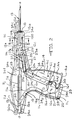
- FIG. 1 is a right side isometric view of the pellet implanting gun apparatus 10 particularly illustrating a handle 11, a head assembly 12 which mounts a carrier 100 with pellets 101, a needle 13 and a trigger 14.
- Figure 2 is a right side, front cross-sectional view along line 2-2 of Figure 1 showing the trigger 14 and actuated linkages 16 and 24 which connect to the head assembly 12 and a drive rod 21 in the rest position.
- Figure 3 is a right side, front view of the pellet implanting gun apparatus 10 showing the trigger 14 partially depressed wherein the pivotable linkage 16 has actuated the drive rod 23 and pellet 101 through the head assembly 12 and into the barrel 13.
- Figure 4 is a right side, front view of the pellet implanting gun apparatus 10 showing the trigger 14 fully depressed wherein the pivotable linkage 24 has actuated the head assembly 12 to pull the needle 13 into the handle 11.
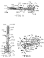
- Figure 5 is a cross-sectional view along line 5-5 of Figure 2 showing the carrier 100 with pellets 101 inserted into the head assembly 12.
- Figure 5A is a cross-sectional view showing the carrier 100 with pellets 101 vertically mounted in a gun apparatus 110 comprised of a handle assembly 111 that is slideably mounted in a head assembly 112.
- Figure 6 is a cross-sectional view along line 6-6 of Figure 1 showing a locking lever 37 holding the head assembly 12 in the handle 11.
- the present invention relates to a hand held gun apparatus for implanting a pellet into an animal which comprises: a hollow needle having a barrel for implanting the pellet into the animal along a longitudinal axis of the needle; a head means being linearly moveable in the gun apparatus along the longitudinal axis, the head means supporting the needle with a first opening along the longitudinal axis and through the head means and into the barrel of the needle, and the head means having a second opening; a carrier means detachably mounted in the second opening in the head means along a second axis, perpendicular to the longitudinal axis, wherein the carrier means is linearly moveable with the head means along the longitudinal axis in a slot in the gun apparatus and provides for a plurality of pellets and wherein the carrier means holds a first pellet along the longitudinal axis and the first opening in the head means so that the first pellet can pass through an opening in the carrier means and the barrel of the needle; a pistol grip means supporting the head means; a drive rod mounted in the pistol grip means and linearly
- the present invention relates to a hand held gun apparatus for implanting a pellet into an animal which comprises: a hollow needle having a barrel for implanting the pellet into the animal along a longitudinal axis of the needle; a head means mounted in a nose of the gun apparatus and being linearly moveable in the gun apparatus along the longitudinal axis, the head means supporting the needle with a first opening along the longitudinal axis and through the head means and into the barrel of the needle, and the head means having a second opening; a carrier means detachably mounted in the second opening of the head means along a second axis perpendicular to the longitudinal axis, wherein the carrier means is linearly moveable with the head means along the longitudinal axis in a slot in the nose of the gun apparatus and provides for a plurality of pellets and wherein the carrier means holds a first pellet in an opening through the carrier means along the longitudinal axis and the first opening in the head means so that the first pellet can pass through an opening in the carrier means and the barrel of the needle; a pistol
- the present invention relates to a hand held gun apparatus for implanting a pellet into an animal which comprises: a hollow needle having a barrel for implanting the pellet into the animal along a longitudinal axis of the needle; a head means mounted in a nose of the gun apparatus and being linearly moveable in the gun apparatus along the longitudinal axis, the head means supporting the needle at a first end and having a second end opposite the first end traversed by a first opening along the longitudinal axis and through the head means and into the barrel of the needle, and the head means having a second opening; a carrier means detachably mounted in the second opening of the head means along a second axis, perpendicular to the longitudinal axis, wherein the carrier means is linearly moveable with the head means along the longitudinal axis in a slot in the nose of the gun apparatus and provides for a plurality of pellets and wherein the carrier means holds a first pellet in an opening through the carrier means, and along the longitudinal axis and the first opening through the head means so that
- the present invention relates to a carrier device for pellets to be injected by means of a hand held gun apparatus which comprises: an elongated bar means having opposed top and bottom ends, opposed front and rear sides and first and second lateral sides between the top and bottom ends wherein there are spaced apart first and second openings in the first and second lateral sides adjacent to the top end, the bar means adapted to be mounted in a head means of the gun apparatus and linearly moveable along the longitudinal axis in a slot in the gun apparatus so that a drive rod can enter the first opening on the first lateral side and move a first pellet out of the second opening in the second lateral side along the longitudinal axis and into a barrel in a needle for implanting the pellet; and a spring means for urging a plate means mounted between the first and second sides of the bar means, from the bottom end to the top end of the bar means so that the plate means advances the pellets along a second axis, perpendicular to the longitudinal axis, for registering a second pellet between the first and
- the present invention in one embodiment relies upon an internal advancing means inside the pellet carrier to automatically register a pellet in the gun apparatus along the longitudinal axis so that the drive rod which travels linearly along the longitudinal axis can move the pellet into the needle that has been inserted into an animal. After the pellet has been moved into the needle, the needle is mechanically retracted into the gun apparatus along the longitudinal axis so that the pellet is deposited in the animal unobstructed by the needle.
- Another possible embodiment of the present invention consists of a pellet carrier that is in a ratchet engagement with a pawl for advancing the carrier through the second opening, along the second axis of the head means. That way, after the gun apparatus has been actuated to implant a first medicament pellet, the trigger is released and the pawl engages the ratchet teeth on the pellet carrier, causing the carrier to advance along the second opening through the head means to register a second medicament pellet along the first opening through the head means.
- a mechanism is used in revolvers, for instance.
- Still another possible embodiment of the present invention consists of a manually operated lever mounted on the moveable head means that is actuated to advance the pellet carrier along the second opening through the head means, after a first medicament pellet has moved from a first pellet chamber and been implanted into an animal. Actuating the lever causes a cam member to engage a first advancing means corresponding to the first pellet chamber which advances the carrier along the second axis to thereby register a second pellet chamber along the first opening through the head means. The lever is then released to move back into a rest position with the cam member moving back over a second advancing means corresponding to the second chamber. A second pellet in the second chamber is now aligned along the first opening through the head means for implanting into an animal.
- Such advancing means are known where the carrier is in a fixed position
- FIGS 1 to 6 show a pellet implanting gun apparatus 10 of the present invention.
- the preferred form of the gun apparatus 10 includes a handle assembly 11, a head assembly 12 supporting a needle 13 and a trigger 14.
- the handle assembly 11 includes a right half 11a and a left half 11b ( Figure 1) which are mirror images of each other.
- the halves 11a and 11b have a nose end 11c, a butt end 11d and a grip portion 11e which receives the trigger 14 when the trigger 14 is actuated.
- a side slot 11f through the right half 11a of the handle assembly 11 in the nose 11c provides for linear movement of a carrier 100 with pellets 101.
- the head assembly 12 has a rectangular cross-section along a plane perpendicular to the axis a-a and provides for an opening or bore 12a (Figure 3).
- An opening 12b through the front side 12c of the head assembly 12 is in communication with the bore 12a for positioning the carrier 100 with pellets 101 along the axis a-a ( Figure 5).
- the needle 13 has a barrel 13a with an angular taper forming into a pointed tip 13b at one end and a flanged section 13c at the other end.
- a nut 15 is mounted on the flanged section 13c and secures the needle 13 to the distal end 12d of the head assembly 12 adjacent to the opening 12b.
- the nut 15 has a gripping outer surface 15a to help remove the needle 13 from the head assembly 12 for changing and cleaning.
- the trigger 14 is formed of spaced apart plates 14a and 14b ( Figure 1) which are mirror images of each other and which are connected together by a front plate 14c and a bottom plate 14d.
- a first pivotable linkage 16 extends from a rod holder 17 to a shuttle linkage pivot pin 18 mounted between the two halves 11a and 11b of the handle assembly 11 adjacent to an arcuate slot 14e in the trigger 14.
- Pivotable linkage 16 is comprised of linkage members 16a and 16b.
- Linkage member 16a is secured to the rod holder 17 through a securing slot (not shown) offset in front of the axis a-a ( Figure 5) by a roll pin 19 and extends to a linkage pin 20.
- the linkage pin 20 pivotably secures the linkage member 16a to the linkage member 16b which extends to the shuttle linkage pivot pin 18.
- the linkage member 16b has a serpentine shape with an enlarged section 16c at its lower end.
- a return spring 21 is mounted between an opening 16d adjacent to the enlarged section 16c and a securing post 22 mounted in the bottom 11i of the handle assembly 11 to hold the linkage members 16a and 16b in the rest position.
- the return spring 21 serves to return the first pivotable linkage 16 and a drive rod 23 mounting the rod holder 17 to their respective rest positions after the gun apparatus 10 has been activated to release a pellet 101.
- Linkage member 24a is secured to the proximal end 12e of the head assembly 12, offset behind the axis a-a ( Figure 5) in a securing slot (not shown) by a roll pin 25 and extends to a linkage pin 26.
- Linkage pin 26 pivotably secures the linkage member 24a to the linkage member 24b which extends to the shuttle linkage pivot pin 18.
- the drive rod 23 When the trigger 14 is in the rest position ( Figure 2), the drive rod 23 is positioned between the bore 12a in the head assembly 12 and the butt end 11d of the handle assembly 11.
- the drive rod 23 is linearly slideable along the axis a-a through the bore 12a and into the barrel 13a of needle 13.
- the drive rod 23 is moved along parallel side rails 11g and 11h on each half 11a and 11b of the handle assembly 11 by the rod holder 17 which slides between the rails 11g and 11h.
- a return spring 27 is mounted between an opening 24c in linkage member 24b adjacent to linkage pin 26 and a securing post 28 adjacent to the proximal end 12e of the head assembly 12 when the head assembly 12 is at rest.
- the return spring 27 serves to return the second pivotable linkage 24 and the head assembly 12 to their respective rest positions after the gun apparatus 10 has been fired.
- a rounded back rest member 29 preferably made of teflon, is provided on shuttle linkage pivot pin 18 between linkage member 16b of the first pivotable linkage 16 and linkage member 24b of the second pivotable linkage 24. Rest member 29 serves both to reduce the wear on return spring 21 against the enlarged section 16c of pivotable linkage 16 and to reduce the sliding friction between the enlarged section 16c and linkage member 24b of the second pivotable linkage 24.
- the right half 11a and the left half 11b of the handle assembly 11 are assembled together by lining up guide pin 30a, hinge pin 30b and shuttle linkage pivot pin 18.
- the two halves 11a and 11b are then secured together with set screws 33a, 33b, 33c, 33d and 33e ( Figure 1) through openings 34a, 34b, 34c, 34d and 34e ( Figure 2 to 4).
- Openings 34f and 34g act as safety mechanisms to prevent the gun apparatus 10 from firing when a guide pin (not shown) is inserted into the openings 34f and 34g.
- a carrier 100 with a plurality of pellets 101 is horizontally mounted through the side slot 11f in the right half 11a of the handle assembly 11 and into the opening 12b in the front side 12c of the head assembly 12.
- the carrier 100 has a rectangular cross-section along the axis b-b and comprises a base plate 102 having a bottom wall 102a ( Figure 5) with spaced apart sidewalls 102b and 102c.
- the sidewalls 102b and 102c each provide for an opening 102f (only opening 102f through sidewall 102b shown in Figure 1) adjacent to the end wall 102d that allows the user to fill the carrier 100 with pellets 101 and which also allows the pellets 101 to be ejected from the carrier 100 when the gun apparatus 10 is actuated.
- the sidewalls 102b and 102c have stepped portions 102g and 102h, respectively, spaced from the opening 102f.
- the side portions 102g and 102h abut against the front side 12c of the head assembly 12 when the carrier 100 is inserted through the side slot 11f and into the front side 12c of the head assembly 12.
- a top plate 103 is secured to the sidewalls 102b and 102c of the bottom plate 102 by mounting screws 104.
- the top plate 103 has a slot 103a that provides for movement of a screw 105 threadably mounted in a plate 106 biased by a spring 107 ( Figure 5).
- the carrier 100 is held in place in the opening 12b in the front side 12c of the head assembly 12 by a securing wire 35 (Figures 1, 5 and 6) that snappingly mates with a groove 102i ( Figure 1) in the sidewalls 102b and 102c (only 102b shown) of the carrier 100.
- the carrier 100 can be vertically mounted in a slot 111a formed in a right half 111b and a left half 111c of a handle assembly 111.
- the carrier 100 is mounted by a securing wire 135 similar to securing wire 35 that snappingly mates with the carrier 100.
- the handle assembly 111 is slideably mounted in an opening 112a in a head assembly 112 of a gun apparatus 110.
- the gun apparatus 110 is similar to the gun apparatus 10.
- the user slides the screw 105 towards the end wall 102e which compresses the spring 107.
- Pellets 101 are then inserted through the opening 102f in either sidewall 102b or 102c until the carrier 100 is full of pellets (partially shown in Figure 5).
- the spring 107 advances the plate 106 and the row of pellets 101 so that the next pellet 101 is positioned along the axis a-a in the opening 102f of the carrier 100 in line with the bore 12a through the head assembly 12 and drive rod 23 for firing into an animal.
- the pellets 101 are implanted subcutaneously into domestic animals such as cattle, sheep, horses and pigs.
- the pellets 101 are usually inserted into the animal's ear because an animal's ear has good blood circulation which allows the pellets 101 to effectively dissolve. Because an animal's ear is not consumed by humans, there is also little risk of a human ingesting a partially dissolved pellet 101.
- the needle 13 is first inserted into the animal's ear to the desired depth.
- the trigger 14 is then actuated by squeezing with the fingers.
- a lever roll pin 36 provided between the spaced apart plates 14a and 14b of the trigger 14 adjacent to the bottom plate 14d, rotates in a semicircular notch 16e in the enlarged section 16c of linkage member 16b before moving over a level surface 16f of the enlarged section 16d.
- the arcuate movement of the linkage member 16b is complete when a semicircular notch 16g in linkage member 16b rests against the hinge pin 30b.
- the rod holder 17 has traveled substantially the entire distance down the rails 11g and 11h of the handle assembly 11, the front end 23a of the drive rod 23 has engaged a pellet 101 in carrier 100 and pushed the pellet 101 out of the bore 12a in the head assembly 12 and through the barrel 13a in needle 13 to the pointed tip 13b at the end of the needle 13.
- the arcuate opening 14e in trigger 14 has traveled the majority of its arcuate extent over the shuttle linkage pivot pin 18.
- a head assembly lock 37 is mounted on the right half 11a of the handle assembly 11 adjacent to the upper end 14f of trigger 14 and the proximal end 12e of the head assembly 12.
- the head assembly lock 37 pivots on a fulcrum pin 39 and locks the head assembly 12 in place when the gun apparatus 10 is in the rest position.
- the trigger 14 is actuated ( Figure 3)
- the upper end 14f of the trigger 14, opposite the hinge pin 30b engages the left arm 37a of the head assembly lock 37, forcing the left arm 37a to pivot upward on fulcrum pin 39 towards the drive rod 23 so that the right arm 37b pivots downward towards the securing post 28, thereby unlocking the head assembly 12.
- the head assembly 12 is now free to travel backwards in a channel 11k formed in the nose end 11c of the handle assembly 11.
- a lever roll pin 41 provided between the spaced apart plates 14a and 14b of the trigger 14 adjacent to the arcuate notch 14e, has just started to engage the linkage member 24b of the second pivotable linkage 24. Further movement of the trigger 14 into the handle assembly 11 causes lever roll pin 41 to force the linkage member 24b to pivot in an arcuate path around the shuttle linkage pivot pin 18. Movement of the linkage member 24b causes linkage member 24a to pivot on linkage pin 26 and move towards the butt end 11d of the handle assembly 11, stretching the return spring 27 and pulling the head assembly 12 and the needle 13 into the gun apparatus 10.
- the linkage pin 26 travels through a recess 11m provided in the left half 11b of the handle assembly 11 as the head assembly 12 travels substantially the entire length of the channel 11k.
- the head assembly 12 pulls the pointed tip 13b of needle 13 out of the animal's ear so that the animal tissue pierced by the needle 13, can close and envelope the pellet 101.
- the gun apparatus 10 is then pulled away from the animal and the trigger 14 is released. Releasing the trigger 14 lets the gun apparatus 10 return to its rest position as shown in Figure 2.
Landscapes
- Health & Medical Sciences (AREA)
- Engineering & Computer Science (AREA)
- Dermatology (AREA)
- Medical Informatics (AREA)
- Anesthesiology (AREA)
- Biomedical Technology (AREA)
- Heart & Thoracic Surgery (AREA)
- Hematology (AREA)
- Life Sciences & Earth Sciences (AREA)
- Animal Behavior & Ethology (AREA)
- General Health & Medical Sciences (AREA)
- Public Health (AREA)
- Veterinary Medicine (AREA)
- Surgical Instruments (AREA)
- Infusion, Injection, And Reservoir Apparatuses (AREA)
Applications Claiming Priority (2)
| Application Number | Priority Date | Filing Date | Title |
|---|---|---|---|
| US07/644,531 US5147295A (en) | 1991-01-23 | 1991-01-23 | Retractable implanter |
| US719391 | 1991-06-24 |
Publications (1)
| Publication Number | Publication Date |
|---|---|
| EP0520367A1 true EP0520367A1 (de) | 1992-12-30 |
Family
ID=24585310
Family Applications (2)
| Application Number | Title | Priority Date | Filing Date |
|---|---|---|---|
| EP19920906266 Withdrawn EP0521150A4 (en) | 1991-01-23 | 1992-01-21 | Improved retractable implanter |
| EP92110547A Withdrawn EP0520367A1 (de) | 1991-01-23 | 1992-06-23 | Verbesserte Pelletträger und Pelletimplantierungsgerät |
Family Applications Before (1)
| Application Number | Title | Priority Date | Filing Date |
|---|---|---|---|
| EP19920906266 Withdrawn EP0521150A4 (en) | 1991-01-23 | 1992-01-21 | Improved retractable implanter |
Country Status (4)
| Country | Link |
|---|---|
| US (2) | US5147295A (de) |
| EP (2) | EP0521150A4 (de) |
| AU (1) | AU1344092A (de) |
| WO (1) | WO1992012744A1 (de) |
Cited By (1)
| Publication number | Priority date | Publication date | Assignee | Title |
|---|---|---|---|---|
| EP1024853A4 (de) * | 1997-10-20 | 2000-09-06 | Ablation Technologies Inc | Vorrichtung zum implantieren von radioaktiver und/oder thermaler kerne |
Families Citing this family (62)
| Publication number | Priority date | Publication date | Assignee | Title |
|---|---|---|---|---|
| NL9101489A (nl) * | 1991-09-03 | 1993-04-01 | Texas Instruments Holland | Injector voor het onderhuids implanteren van een voorwerp in een levend wezen. |
| US5279555A (en) * | 1992-08-24 | 1994-01-18 | Merck & Co., Inc. | Device for injecting implants |
| USD369657S (en) | 1992-09-30 | 1996-05-07 | Bristol-Myers Squibb Co. | Dispenser for tissue glue |
| WO1995019799A1 (en) * | 1994-01-21 | 1995-07-27 | Agracetus, Inc. | Gas driven gene delivery instrument |
| AU123112S (en) * | 1994-02-08 | 1995-03-31 | Roussel Uclaf | Cassette for 10 implants |
| DE9417574U1 (de) * | 1994-11-02 | 1996-03-07 | Neumann, Kurt, 91080 Uttenreuth | Medizinische Vorrichtung zum Einführen von medizinischen Anordnungen ect. durch Gewebeschichten in den Körper |
| US5522797A (en) * | 1995-01-03 | 1996-06-04 | Ivy Laboratories, Inc. | Slide action veterinary implanter |
| AU1331497A (en) | 1995-12-18 | 1997-07-14 | Kerisma Medical Products, L.L.C. | Fiberoptic-guided interstitial seed manual applicator and seed cartridge |
| US5817054A (en) * | 1996-11-12 | 1998-10-06 | Ivy Laboratories, Inc. | Veterinary implanter with disinfectant dispenser |
| US6183444B1 (en) * | 1998-05-16 | 2001-02-06 | Microheart, Inc. | Drug delivery module |
| US5951517A (en) * | 1997-10-14 | 1999-09-14 | Merit Medical Systems, Inc. | One-hand pulse pump |
| WO2000005726A1 (en) * | 1998-07-20 | 2000-02-03 | Emory University | Disposable container for irradiation pellets |
| US7983734B2 (en) | 2003-05-23 | 2011-07-19 | Senorx, Inc. | Fibrous marker and intracorporeal delivery thereof |
| US9820824B2 (en) | 1999-02-02 | 2017-11-21 | Senorx, Inc. | Deployment of polysaccharide markers for treating a site within a patent |
| US8361082B2 (en) | 1999-02-02 | 2013-01-29 | Senorx, Inc. | Marker delivery device with releasable plug |
| WO2000067825A1 (en) | 1999-05-07 | 2000-11-16 | Microheart, Inc. | Apparatus and method for delivering therapeutic and diagnostic agents |
| US7147633B2 (en) * | 1999-06-02 | 2006-12-12 | Boston Scientific Scimed, Inc. | Method and apparatus for treatment of atrial fibrillation |
| US6641553B1 (en) | 1999-06-02 | 2003-11-04 | Boston Scientific Corporation | Devices and methods for delivering a drug |
| US6575991B1 (en) | 1999-06-17 | 2003-06-10 | Inrad, Inc. | Apparatus for the percutaneous marking of a lesion |
| USD448482S1 (en) | 2000-05-18 | 2001-09-25 | Integrated Implant Systems, L.L.C. | Medical implantation instrument |
| US7588554B2 (en) | 2000-06-26 | 2009-09-15 | Boston Scientific Scimed, Inc. | Method and apparatus for treating ischemic tissue |
| EP1411851B1 (de) * | 2001-08-03 | 2006-11-02 | Tyco Healthcare Group LP | Marker zur verwendung mit einem gewebemarkierungsgerät |
| US20060036158A1 (en) | 2003-11-17 | 2006-02-16 | Inrad, Inc. | Self-contained, self-piercing, side-expelling marking apparatus |
| IL157981A (en) | 2003-09-17 | 2014-01-30 | Elcam Medical Agricultural Cooperative Ass Ltd | Auto-injector |
| US20050234475A1 (en) * | 2004-03-04 | 2005-10-20 | Cordes Christopher J | Transponder implanter |
| IL160891A0 (en) | 2004-03-16 | 2004-08-31 | Auto-mix needle | |
| US7588528B2 (en) * | 2004-08-24 | 2009-09-15 | C. R. Bard, Inc. | Brachytherapy apparatus for dispensing medication |
| CA2593848C (en) * | 2005-01-24 | 2012-08-07 | N.V. Organon | Applicator for inserting an implant |
| US10357328B2 (en) | 2005-04-20 | 2019-07-23 | Bard Peripheral Vascular, Inc. and Bard Shannon Limited | Marking device with retractable cannula |
| JP5168695B2 (ja) * | 2006-01-19 | 2013-03-21 | エム・エス・ディー・オス・ベー・フェー | インプラントを挿入するためのアプリケータを組み立てるためのキット及びその方法 |
| GB2437783B (en) * | 2006-04-26 | 2011-11-02 | Summit Medical Ltd | A medical treatment material delivery apparatus |
| TWI332851B (en) * | 2007-04-27 | 2010-11-11 | Dermato Plastica Beauty Dpb Co Ltd | Volume adjustable, micro-injection device |
| US9839772B2 (en) | 2008-05-06 | 2017-12-12 | Cook Medical Technologies Llc | Apparatus and methods for delivering therapeutic agents |
| AU2009256236A1 (en) | 2008-06-04 | 2009-12-10 | Neovista, Inc. | Handheld radiation delivery system for advancing a radiation source wire |
| US7824359B2 (en) * | 2008-07-24 | 2010-11-02 | Solomon Clifford T | Bioinjection device |
| CA2747390C (en) * | 2008-12-23 | 2016-10-04 | Wilson-Cook Medical Inc. | Apparatus and methods for containing and delivering therapeutic agents |
| CN102256660B (zh) | 2008-12-30 | 2013-07-03 | C·R·巴德公司 | 用于组织标记物放置的标记物输送装置 |
| US8118777B2 (en) | 2009-05-29 | 2012-02-21 | Cook Medical Technologies Llc | Systems and methods for delivering therapeutic agents |
| US9101744B2 (en) | 2009-05-29 | 2015-08-11 | Cook Medical Technologies Llc | Systems and methods for delivering therapeutic agents |
| EP2335771A1 (de) * | 2009-12-21 | 2011-06-22 | forteq Nidau AG | Vorrichtung zur Injektion eines Feststoffes |
| USD636951S1 (en) | 2010-01-29 | 2011-04-26 | Biomark, Inc. | Tag gun |
| IT1404712B1 (it) * | 2011-02-25 | 2013-11-29 | Thd Spa | Dispositivo per impiantare una protesi in un tessuto. |
| IT1405423B1 (it) * | 2011-02-25 | 2014-01-10 | Thd Spa | Dispositivo per impiantare una protesi in un tessuto |
| US9585672B2 (en) | 2011-02-25 | 2017-03-07 | Thd S.P.A. | Device for implanting a prosthesis in a tissue |
| US8657760B2 (en) | 2011-03-04 | 2014-02-25 | Cook Medical Technologies Llc | Ergonomic biopsy instrument |
| ITMO20110184A1 (it) * | 2011-07-25 | 2013-01-26 | Lameplast Spa | Dispositivo per introdurre sostanze all'interno di animali |
| US11931227B2 (en) | 2013-03-15 | 2024-03-19 | Cook Medical Technologies Llc | Bimodal treatment methods and compositions for gastrointestinal lesions with active bleeding |
| US9867931B2 (en) | 2013-10-02 | 2018-01-16 | Cook Medical Technologies Llc | Therapeutic agents for delivery using a catheter and pressure source |
| CN106029019B (zh) | 2014-02-26 | 2020-07-03 | 阿勒根公司 | 眼内植入体递送设备及其使用方法 |
| US10219882B1 (en) * | 2014-12-22 | 2019-03-05 | Edgar C. Cohen, Jr. | Animal pill delivery device |
| US10342742B2 (en) * | 2015-04-07 | 2019-07-09 | Kenneth Edward Ruda | Bolus feeding device |
| USD860451S1 (en) | 2016-06-02 | 2019-09-17 | Intarcia Therapeutics, Inc. | Implant removal tool |
| USD840030S1 (en) | 2016-06-02 | 2019-02-05 | Intarcia Therapeutics, Inc. | Implant placement guide |
| EP3703804B1 (de) | 2017-11-02 | 2022-02-16 | IsoRay Medical, Inc. | Vorrichtung zum laden von brachytherapiesamen in implantationshülsen |
| USD933219S1 (en) | 2018-07-13 | 2021-10-12 | Intarcia Therapeutics, Inc. | Implant removal tool and assembly |
| BR112022023464A2 (pt) | 2020-06-05 | 2022-12-20 | Cook Medical Technologies Llc | Endoscópios médicos para entregar agentes terapêuticos |
| US11553701B1 (en) | 2021-07-12 | 2023-01-17 | Oliver Green | Rattle insertion device for elastomeric fishing lure and method of use |
| WO2023287654A1 (en) | 2021-07-14 | 2023-01-19 | Cook Medical Technologies, LLC | Systems and methods for preventing clogging of a delivery system |
| CN113662701B (zh) * | 2021-07-15 | 2024-01-26 | 北京思灵机器人科技有限责任公司 | 击发装置及自动注射设备 |
| BE1030751B1 (nl) * | 2022-08-02 | 2024-03-04 | Metagam Bvba | Pistool voor het inplanten van een microchip in een dier |
| US12496429B2 (en) | 2022-10-18 | 2025-12-16 | Cook Medical Technologies Llc | Systems and methods for delivering pressurized fluid to a target site alone or in conjunction with therapeutic agents |
| USD1135579S1 (en) * | 2025-06-22 | 2026-07-21 | Yiwu Yongxin Daily Necessities Co., Ltd. | Tag pin gun |
Citations (5)
| Publication number | Priority date | Publication date | Assignee | Title |
|---|---|---|---|---|
| US4105030A (en) * | 1977-01-03 | 1978-08-08 | Syntex (U.S.A.) Inc. | Implant apparatus |
| US4223674A (en) * | 1978-06-29 | 1980-09-23 | Arthur J. McIntosh | Implant gun |
| US4447223A (en) * | 1982-04-16 | 1984-05-08 | Cct Associates | Medicament implant applicator |
| US4661103A (en) * | 1986-03-03 | 1987-04-28 | Engineering Development Associates, Ltd. | Multiple implant injector |
| GB2227413A (en) * | 1988-12-06 | 1990-08-01 | Englund Anne Margaret | Implant gun |
Family Cites Families (15)
| Publication number | Priority date | Publication date | Assignee | Title |
|---|---|---|---|---|
| US3402712A (en) * | 1966-07-19 | 1968-09-24 | American Home Prod | Pellet implanter |
| US3669104A (en) * | 1970-06-15 | 1972-06-13 | Pfizer | Implant gun |
| US3774607A (en) * | 1971-11-22 | 1973-11-27 | Commercial Solvents Corp | Pellet implant gun |
| US4004565A (en) * | 1975-04-14 | 1977-01-25 | Minnesota Mining And Manufacturing Company | Clip for supplying implant projectiles |
| GB1525841A (en) * | 1976-05-18 | 1978-09-20 | Hundon Forge Ltd | Drug implanters |
| US4077406A (en) * | 1976-06-24 | 1978-03-07 | American Cyanamid Company | Pellet implanter for animal treatment |
| GB1583816A (en) * | 1978-05-22 | 1981-02-04 | Hundon Forge Ltd | Pellet magazine |
| US4403610A (en) * | 1980-06-19 | 1983-09-13 | N.J. Phillips Pty. Limited | Gun to implant pellets in animals |
| US4474572A (en) * | 1981-09-29 | 1984-10-02 | Syntex (U.S.A.) Inc. | Implanting device and implant magazine |
| US4451254A (en) * | 1982-03-15 | 1984-05-29 | Eli Lilly And Company | Implant system |
| US4576591A (en) * | 1983-07-06 | 1986-03-18 | Ivy-Gene Co., Inc. | Medicament implant applicator |
| US4531938A (en) * | 1983-07-06 | 1985-07-30 | Ivy-Gene Co., Inc. | Medicament implant applicator |
| US4687465A (en) * | 1986-04-25 | 1987-08-18 | Ideal Instruments, Inc. | Automatic clip or pellet carrier fed pellet implanter apparatus |
| GB2190590B (en) * | 1986-05-20 | 1990-02-21 | Hundon Forge Ltd | Improved actuator mechanism for implanters |
| US4988335A (en) * | 1988-08-16 | 1991-01-29 | Ideal Instruments, Inc. | Pellet implanter apparatus |
-
1991
- 1991-01-23 US US07/644,531 patent/US5147295A/en not_active Expired - Lifetime
- 1991-06-24 US US07/719,391 patent/US5106370A/en not_active Expired - Lifetime
-
1992
- 1992-01-21 AU AU13440/92A patent/AU1344092A/en not_active Abandoned
- 1992-01-21 EP EP19920906266 patent/EP0521150A4/en not_active Withdrawn
- 1992-01-21 WO PCT/US1992/000565 patent/WO1992012744A1/en not_active Ceased
- 1992-06-23 EP EP92110547A patent/EP0520367A1/de not_active Withdrawn
Patent Citations (5)
| Publication number | Priority date | Publication date | Assignee | Title |
|---|---|---|---|---|
| US4105030A (en) * | 1977-01-03 | 1978-08-08 | Syntex (U.S.A.) Inc. | Implant apparatus |
| US4223674A (en) * | 1978-06-29 | 1980-09-23 | Arthur J. McIntosh | Implant gun |
| US4447223A (en) * | 1982-04-16 | 1984-05-08 | Cct Associates | Medicament implant applicator |
| US4661103A (en) * | 1986-03-03 | 1987-04-28 | Engineering Development Associates, Ltd. | Multiple implant injector |
| GB2227413A (en) * | 1988-12-06 | 1990-08-01 | Englund Anne Margaret | Implant gun |
Cited By (1)
| Publication number | Priority date | Publication date | Assignee | Title |
|---|---|---|---|---|
| EP1024853A4 (de) * | 1997-10-20 | 2000-09-06 | Ablation Technologies Inc | Vorrichtung zum implantieren von radioaktiver und/oder thermaler kerne |
Also Published As
| Publication number | Publication date |
|---|---|
| EP0521150A1 (de) | 1993-01-07 |
| EP0521150A4 (en) | 1993-07-28 |
| US5106370A (en) | 1992-04-21 |
| WO1992012744A1 (en) | 1992-08-06 |
| US5147295A (en) | 1992-09-15 |
| AU1344092A (en) | 1992-08-27 |
Similar Documents
| Publication | Publication Date | Title |
|---|---|---|
| US5106370A (en) | Pellet carrier fed pellet implanter apparatus | |
| US10821277B2 (en) | Kit for and method of assembling an applicator for inserting an implant | |
| EP0831743B1 (de) | Automatische biopsieinstrumente | |
| US5904693A (en) | Automatic laparoscopic ligation clip applicator | |
| EP2407112B1 (de) | Gerät zur Entnahme von mindestens einer Probe Gewebe | |
| US4447223A (en) | Medicament implant applicator | |
| AU653243B2 (en) | Injector for hypodermically implanting an object in a living being | |
| US4958625A (en) | Biopsy needle instrument | |
| US5250026A (en) | Adjustable precision transponder injector | |
| US5514101A (en) | Pistal grip implantation device with push back bar | |
| US7063672B2 (en) | Integrated biopsy needle assembly | |
| HU192109B (en) | Instrument for intrarumen injecting ruminants | |
| JPH05507872A (ja) | サンプル寸法を制御する調節可能生検針装置 | |
| US9072508B2 (en) | Device for taking at least one sample of tissue | |
| CA2070488A1 (en) | Pellet carrier fed pellet implanter apparatus | |
| GB2190590A (en) | Actuator mechanism for implanters | |
| CN219462173U (zh) | 换针机构及注射装置 | |
| US9901326B2 (en) | Device for taking at least one sample of tissue | |
| GB2174606A (en) | Pellet implanter | |
| AU2007206957B2 (en) | Kit for and method of assembling an applicator for inserting an implant | |
| KR910003435Y1 (ko) | 사혈기 | |
| GB2331705A (en) | Tool for administering injections to livestock |
Legal Events
| Date | Code | Title | Description |
|---|---|---|---|
| PUAI | Public reference made under article 153(3) epc to a published international application that has entered the european phase |
Free format text: ORIGINAL CODE: 0009012 |
|
| 17P | Request for examination filed |
Effective date: 19920623 |
|
| AK | Designated contracting states |
Kind code of ref document: A1 Designated state(s): AT BE CH DE DK ES FR GB GR IT LI LU MC NL PT SE |
|
| 17Q | First examination report despatched |
Effective date: 19940808 |
|
| STAA | Information on the status of an ep patent application or granted ep patent |
Free format text: STATUS: THE APPLICATION IS DEEMED TO BE WITHDRAWN |
|
| 18D | Application deemed to be withdrawn |
Effective date: 19941220 |