EP0520472B1 - "On-line" Feuchtigkeitsmessystem für pulverförmige oder körnige Stoffe - Google Patents
"On-line" Feuchtigkeitsmessystem für pulverförmige oder körnige Stoffe Download PDFInfo
- Publication number
- EP0520472B1 EP0520472B1 EP92110783A EP92110783A EP0520472B1 EP 0520472 B1 EP0520472 B1 EP 0520472B1 EP 92110783 A EP92110783 A EP 92110783A EP 92110783 A EP92110783 A EP 92110783A EP 0520472 B1 EP0520472 B1 EP 0520472B1
- Authority
- EP
- European Patent Office
- Prior art keywords
- materials
- moisture
- dehumidified
- sampled
- moisture measuring
- Prior art date
- Legal status (The legal status is an assumption and is not a legal conclusion. Google has not performed a legal analysis and makes no representation as to the accuracy of the status listed.)
- Expired - Lifetime
Links
- 239000008187 granular material Substances 0.000 title claims abstract description 36
- 239000012254 powdered material Substances 0.000 title claims abstract description 36
- 239000000463 material Substances 0.000 claims abstract description 188
- 239000006200 vaporizer Substances 0.000 claims abstract description 37
- 238000009834 vaporization Methods 0.000 claims abstract description 29
- 230000008016 vaporization Effects 0.000 claims abstract description 29
- 239000012159 carrier gas Substances 0.000 claims abstract description 27
- 238000005070 sampling Methods 0.000 claims abstract description 25
- XLYOFNOQVPJJNP-UHFFFAOYSA-N water Substances O XLYOFNOQVPJJNP-UHFFFAOYSA-N 0.000 claims abstract description 15
- 238000005303 weighing Methods 0.000 claims abstract description 15
- XNWFRZJHXBZDAG-UHFFFAOYSA-N 2-METHOXYETHANOL Chemical compound COCCO XNWFRZJHXBZDAG-UHFFFAOYSA-N 0.000 claims abstract description 14
- 238000010438 heat treatment Methods 0.000 claims abstract description 14
- 238000006243 chemical reaction Methods 0.000 claims abstract description 4
- 238000010926 purge Methods 0.000 claims description 10
- 238000004891 communication Methods 0.000 claims description 3
- 230000032258 transport Effects 0.000 abstract description 8
- 239000011347 resin Substances 0.000 description 48
- 229920005989 resin Polymers 0.000 description 48
- 239000007788 liquid Substances 0.000 description 7
- 238000005259 measurement Methods 0.000 description 7
- 238000000034 method Methods 0.000 description 7
- 238000010276 construction Methods 0.000 description 6
- 239000007789 gas Substances 0.000 description 6
- 239000011261 inert gas Substances 0.000 description 4
- OKKJLVBELUTLKV-UHFFFAOYSA-N Methanol Chemical compound OC OKKJLVBELUTLKV-UHFFFAOYSA-N 0.000 description 3
- 238000010586 diagram Methods 0.000 description 3
- 238000007599 discharging Methods 0.000 description 3
- 230000006872 improvement Effects 0.000 description 3
- 238000012423 maintenance Methods 0.000 description 3
- NJPPVKZQTLUDBO-UHFFFAOYSA-N novaluron Chemical compound C1=C(Cl)C(OC(F)(F)C(OC(F)(F)F)F)=CC=C1NC(=O)NC(=O)C1=C(F)C=CC=C1F NJPPVKZQTLUDBO-UHFFFAOYSA-N 0.000 description 3
- 238000012546 transfer Methods 0.000 description 3
- IJGRMHOSHXDMSA-UHFFFAOYSA-N Atomic nitrogen Chemical compound N#N IJGRMHOSHXDMSA-UHFFFAOYSA-N 0.000 description 2
- 238000004458 analytical method Methods 0.000 description 2
- 238000007664 blowing Methods 0.000 description 2
- 239000003153 chemical reaction reagent Substances 0.000 description 2
- 229910001873 dinitrogen Inorganic materials 0.000 description 2
- 238000000465 moulding Methods 0.000 description 2
- 238000004448 titration Methods 0.000 description 2
- 230000007306 turnover Effects 0.000 description 2
- 238000006641 Fischer synthesis reaction Methods 0.000 description 1
- BQCADISMDOOEFD-UHFFFAOYSA-N Silver Chemical compound [Ag] BQCADISMDOOEFD-UHFFFAOYSA-N 0.000 description 1
- 239000006096 absorbing agent Substances 0.000 description 1
- 239000000919 ceramic Substances 0.000 description 1
- 230000008859 change Effects 0.000 description 1
- 238000004737 colorimetric analysis Methods 0.000 description 1
- 238000012790 confirmation Methods 0.000 description 1
- 238000007796 conventional method Methods 0.000 description 1
- 238000001816 cooling Methods 0.000 description 1
- 238000003869 coulometry Methods 0.000 description 1
- 230000007547 defect Effects 0.000 description 1
- 238000001035 drying Methods 0.000 description 1
- 239000000284 extract Substances 0.000 description 1
- 239000011521 glass Substances 0.000 description 1
- 229910010272 inorganic material Inorganic materials 0.000 description 1
- 239000011147 inorganic material Substances 0.000 description 1
- 238000003780 insertion Methods 0.000 description 1
- 230000037431 insertion Effects 0.000 description 1
- 239000002655 kraft paper Substances 0.000 description 1
- 229910001120 nichrome Inorganic materials 0.000 description 1
- 239000013307 optical fiber Substances 0.000 description 1
- 230000008569 process Effects 0.000 description 1
- 229910052709 silver Inorganic materials 0.000 description 1
- 239000004332 silver Substances 0.000 description 1
- 239000011800 void material Substances 0.000 description 1
- 238000004804 winding Methods 0.000 description 1
Images


Classifications
-
- G—PHYSICS
- G01—MEASURING; TESTING
- G01N—INVESTIGATING OR ANALYSING MATERIALS BY DETERMINING THEIR CHEMICAL OR PHYSICAL PROPERTIES
- G01N5/00—Analysing materials by weighing, e.g. weighing small particles separated from a gas or liquid
- G01N5/04—Analysing materials by weighing, e.g. weighing small particles separated from a gas or liquid by removing a component, e.g. by evaporation, and weighing the remainder
- G01N5/045—Analysing materials by weighing, e.g. weighing small particles separated from a gas or liquid by removing a component, e.g. by evaporation, and weighing the remainder for determining moisture content
-
- G—PHYSICS
- G01—MEASURING; TESTING
- G01N—INVESTIGATING OR ANALYSING MATERIALS BY DETERMINING THEIR CHEMICAL OR PHYSICAL PROPERTIES
- G01N1/00—Sampling; Preparing specimens for investigation
- G01N1/02—Devices for withdrawing samples
- G01N1/10—Devices for withdrawing samples in the liquid or fluent state
- G01N1/20—Devices for withdrawing samples in the liquid or fluent state for flowing or falling materials
Definitions
- the present invention is related to an improvement of an on-line moisture measuring apparatus wherein powdered or granular materials including inorganic materials such as pelletized resin materials and ceramics are automatically sampled and the moisture content thereof is automatically measured.
- a titration analysis using a Karl Fischer reagent has been conventionally known as a method for titrating and analyzing the moisture content of resin materials.
- a moisture meter has been developed in which titration analysis by a Karl Fischer reagent is performed by means of a coulometric method, a volumetric method, and a colorimetric method, whereby a high accuracy can be obtained.
- JP-A-3-63558 EP-A-0 411 848
- powdered or granular materials such as resin materials are automatically sampled and their moisture content is measured by means of a Karl Fischer reagent employing inert gas as a carrier gas.
- This system comprises :
- the method employed an inert gas such as nitrogen gas as a carrier gas for a Karl Fischer reagent. Therefore, a gas cylinder containing inert gas should be regularly exchanged and pipings were increased and complexed. Furthermore, a gas cylinder should be frequently exchanged when the system was used many times and consequently the consumption of inert gas increased. Therefore, the mentioned concept leaves further room for improvement from the view point of maintenance.
- an inert gas such as nitrogen gas as a carrier gas for a Karl Fischer reagent. Therefore, a gas cylinder containing inert gas should be regularly exchanged and pipings were increased and complexed. Furthermore, a gas cylinder should be frequently exchanged when the system was used many times and consequently the consumption of inert gas increased. Therefore, the mentioned concept leaves further room for improvement from the view point of maintenance.
- the present invention is proposed to solve the abovementioned problems and an object of the present invention is to provide an on-line moisture measuring system wherein maintenance is facilitated by eliminating exchange of gas cylinders.
- sampling means designed to be attached to a material storage container storing powdered or granular materials for sampling a fixed amount of the materials and for pneumatically transporting the sampled materials
- dehumidified and dried air supply means having an air supply source for generating dehumidified and dried air by heating and dehumidifying the air supplied from the air supply source
- material weighing means for weighing the sampled materials fed from the sampling means
- a vaporization treatment chamber including an airtight vaporizer with a heater and having a sample boat for receiving the materials weighed by the material weighing means.
- the airtight vaporizer heats the weighed materials received in the sample boat while receiving the dehumidified and dried air supplied from the dehumidified and dried air supply means as a carrier gas.
- the on-line moisture measuring system is also provided with a moisture measuring chamber including a moisture meter for measuring the moisture quantity of the weighed materials by the reaction of a Karl Fischer reagent by receiving the vapor generated in the vaporizer together with the carrier gas.
- the on-line moisture measuring system is further provided with an arithmetic operation unit for calculating the moisture content of the sampled and weighed materials based on the moisture quantity measured by the moisture measuring chamber and the weight value weighed by the material measuring means.
- a fixed amount of powdered or granular materials sampled from the material storage container is repeatedly supplied each time the sampled materials are treated in the vaporization treatment chamber so as to get the moisture content of the sampled materials.
- Another on-line moisture measuring system further comprises a communication passage communicating the vaporization treatment chamber and the moisture measuring chamber, and air purge means for purging the dehumidified and dried air supplied from the dehumidified and dried air supply means from both the vaporization treatment chamber and the moisture measuring chamber respectively into atmosphere.
- transportation of the sampled materials into the vaporization treatment chamber is performed by the dehumidified and dried air supplied from the dehumidified and dried air supply means is used as a transport air.
- Sampled powdered or granular materials are fed from the material storage container, weighed by the material weighing means, received in the sample boat, carried in the vaporization treatment chamber, and heated therein.
- the carrier gas which is dehumidified and dried so as to have a low dew point, is fed into the moisture measuring chamber side in the vaporization treatment chamber from the dehumidified and dried air supply means.
- the moisture discharged from the heated powdered or granular materials in the form of a vapor is fed into the moisture measuring chamber together with the carrier gas.
- Moisture measurement by means of a Karl Fischer reagent is performed in the moisture measuring chamber.
- the measured water quantity is sent to the operation unit together with the weight value measured by the material weighing means.
- the moisture content of the materials is calculated, sample data such as the date and time of sampling and a sample port number are output, and they are recorded and stored.
- the sample boat is taken out of the vaporizer and the heated materials on the sample boat are discharged.
- powdered or granular materials are automatically sampled, fed into the vaporization treatment chamber, heated therein, measured concerning their moisture content, and automatically discharged after the moisture measurement has been finished.
- sampling, heat treatment, moisture measurement and discharge of powdered or granular materials can be repeated unmanned.
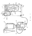
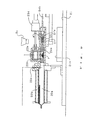
- Fig. 1 is a schematic view of an on-line moisture control system for pelletized resin materials employing an on-line moisture measuring apparatus of the present invention.
- a main body 10 of a moisture measuring apparatus A includes a vaporization treatment chamber 2 containing a vaporizer 20a which heats sampled and weighed pelletized resin materials (not shown) and extracts water from the pelletized resin materials in the form of a vapor while a carrier gas dehumidified and dried to have a low dew point is supplied.
- the main body 10 of the moisture measuring apparatus A also includes a moisture measuring chamber 4 containing a moisture meter 41 which measures the water quantity of the pelletized resin materials by reacting the extracted water and the carrier gas with a Karl Fischer reagent. Casters 1Oa, 1Oa are provided under the main body 10 for conveying the main body 10.
- Dehumidified and dried air supply means 1 (see Fig. 2) provided in the moisture measuring apparatus A supplies dehumidified and dried air through an air supply pipe 8 toward sampling means 6 provided at the bottom of a hopper dryer (a material storing container B ) storing pelletized resin materials. Consequently a fixed amount of pelletized resin materials is sampled and automatically fed into the vaporization treatment chamber 2 through sample ports 3a provided as material insert ports at the top of the vaporization treatment chamber 2 in the moisture measuring apparatus A .
- the numeral 5 indicates a display and operation panel for inputting data required for an arithmetic operation unit 11 (see Fig. 3) corresponding to the powdered or granular materials to be measured their moisture content.
- a communication pipe 7 communicates the vaporization treatment chamber 2 and the moisture measuring chamber 4 and includes an air purge means for blowing the dehumidified and dried air fed from the dehumidified and dried air supply means 1 into the vaporization treatment chamber 2 and the moisture measuring chamber 4 and for discharging the air from respective chambers to atmosphere.
- moisture measuring apparatus A of the present invention moisture measurement can be performed under more preferable conditions because atmospheric air can be prevented from entering, and the vaporization treatment chamber 2 and the moisture measuring chamber 4 are kept under highly dry condition.
- an air source can be used commonly because a transport air for transporting sampled powdered or granular materials into the vaporization treatment chamber 2 can be supplied from the dehumidified and dried air supply means 1.
- a rotary sampling apparatus for powdered or granular materials can be employed as a sampling apparatus used for the on-line moisture measuring system of the present invention.
- a sampling apparatus When such a sampling apparatus is used, a fixed amount of sampled powdered or granular materials can easily be entrapped in the vaporization treatment chamber 2 only by appropriately supplying dehumidified and dried air from the moisture measuring apparatus A .
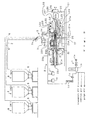
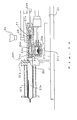
- Fig. 2 shows the vaporization treatment chamber 2 and the dehumidified and dried air supply means 1 in the moisture measuring apparatus A .
- the top of the vaporization treatment chamber 2 is provided with the three sample ports 3a as the material insert ports corresponding to three hopper dryers B (#1) - (#3) which are storing containers for powdered or granular materials.
- Material measuring means 3 is provided with a load cell 31 for weighing sampled pelletized resin materials, and a cylindrical material insert chute 3c having a damper 3b.
- a load cell 31 for weighing sampled pelletized resin materials
- a cylindrical material insert chute 3c having a damper 3b.
- the vaporizer 20a is made of a heat-resistant glass and the like and it serves as a heating part by winding a heater 20b around its periphery. Nesa electrodes or Nichrome wires are used for the heater 20b. When Nesa electrodes are used, powdered or granular materials in the body of the vaporization treatment chamber 2 can be made thin and compact.
- the vaporizer 20a is preferably heated and maintained at a temperature just before powdered or granular materials are dissolved in order to vaporize all the water contained in the powdered or granular materials.
- a temperature control apparatus controls the vaporizer 20a to keep it at an appropriate temperature before the materials are received therein.
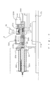
- a sample boat 24 having a receiver 24a is contained in a cylindrical body 25, an opening end 25a of which is provided for putting the sample boat 24 in and out and is connected with the vaporizer 20a.
- the sample boat 24 is connected with a rod 24b of a second slide cylinder 24c, and the receiver 24a of the sample boat 24 is freely put in and out of the vaporizer 20a through an opening 20d by sliding the cylinder 24c forward and backward.
- the sample boat 24 is controlled concerning its insertion, withdrawal or discharge confirmation position by advancing or retreating operation of a first slide cylinder 23c and the sample boat 24 is provided with limit switches LS6, LS5 and LS9 to enable such a position control.
- Fig. 14 shows a detailed construction of the sample boat 24.
- the cylinder rod 24b is fixed with a scraper 24e at the initial end thereof and connected with a small rod 24f fitted with a spring 27 and a stopper ring 27a at its periphery.
- the sample boat 24 is constructed such that the scraper 24e can be put in and out of a material receiving space 24g of the vessel-like receiver 24a.
- the scraper 24e is kept retracting in the material receiving space 24g of the receiver 24a when the spring 27 is expanded as shown in Fig. 11.
- the central axis of the cylindrical body 25 containing the sample boat 24 is slightly and downwardly off-centered ( x ) with the central axis of the vaporizer 20a.
- the receiver 24a of the sample boat 24 can enter in the vaporizer 20a without any resistance when the cylinder rod 24b is forwarded, when material transferring means 23 is positioned over the sample boat 24 as shown in Figs. 8 - 10.
- the material transferring means 23 is provided over the cylindrical body 25 containing the sample boat 24.
- the material transferring means 23 receives pelletized resin materials fallen and inserted from the material insert chute 3c and transfers the pelletized resin materials to the receiver 24a of the sample boat 24.
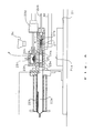
- a cylinder rod 23b of the first slide cylinder 23c is connected at the rear of the material transport means 23.
- the numeral 23d indicates an air-operated first rotary actuator.
- the first slide cylinder 23c is designed to move the rod 23b back and forth and the first rotary actuator 23d is designed to rotate the rod 23b, whereby the receiver 23a of the material transferring means 23 can move back and forth and rotate up and down.
- the material transferring means 23 is controlled to be positioned at a material receiving position, a material transfer position, a turn over position and a return position, respectively, by sliding operation of the slide cylinder 23c and turning over operation of the first rotary actuator 23d.
- the material transferring means 23 is provided with limit switches LS2, LS1 and LS3. (Fig. 2)
- the cylindrical body 25 containing the vaporizer 20a and the sample boat 24 is fixed on a pedestal 21 with supports 22.
- the cylindrical body 25 is constructed such that it can be rotated separating from the vaporizer 20a by means of the second rotary actuator 26 provided at one support 22.
- limit switches LS7 and LS8 are provided for detecting the turn over position and the return position of the second rotary actuator 26.
- the numeral 21a indicates a material disposal container provided on the pedestal 21.
- the cylindrical body 25 and the material transferring means 23 are integrally fixed such that their vertical position is reversed when the second rotary actuator 26 is turned over, because the cylinder 23c is fixed on the cylindrical body 25 (See Fig. 12).
- a material receiving port 25b is provided at the top of the cylindrical body 25 and a cover 23h for sliding the material transferring means 23 is formed so as to cover the material receiving port 25b.
- the material transferring means 23 reciprocates between the material insert chute 3c and the cover 23h.
- the material transferring means 23 receives the pelletized resin materials fallen from the material insert chute 3c in the receiver 23a thereof, moves into the cover 23h, delivers the pelletized resin materials to the receiver 24a of the sample boat 24 by turning over.
- the transfer of the pelletized resin materials is accomplished.
- the first cylinder 23c and the first rotary actuator 23d are constructed so as to rotate and slide the material transferring means 23 by means of the rod 23b.
- a carrier gas transport pipe (not shown) is connected at the tip 20c of the vaporizer 20a for feeding the vapor generated in the vaporizer 20a to the moisture meter 41 in the moisture measuring chamber 4 together with a carrier gas.
- the dehumidified and dried air supply means 1 includes an air supply source 1a, heats and dehumidifies the air supplied from the air supply source 1a so as to have a low dew point (for example, from -70 °C to -40 °C), and supplies the air.
- a low dew point for example, from -70 °C to -40 °C
- Air supplied from the air supply source 1a such as a compressor is dehumidified by a heatless dryer 1b so as to satisfy a fixed level of a dew point, measured concerning the supply pressure and the flow amount thereof by a regulator 1c and an air flow meter 1d, and supplied to the vaporizer 20a from a carrier gas introduction port 20e through moisture absorbers 1e and 1f.
- the dehumidified and dried air thus supplied to the vaporizer 20a is fed to the moisture meter 41 together with the vapor generated by heating the pelletized resin materials in the sample boat 24.
- the air supply means 1 can divergently use the air dehumidified and dried by the heatless dryer 1b as a transport air for sampling, as control air for the slide cylinders and the actuators, and as purge air for the air purge means.
- the cover 23h containing the receiver 23a of the materials transport means 23 is provided with a hole 23f corresponding to a hole 23e formed at the top of the receiver 23a.
- the moisture measuring chamber 4 receives vapor supplied from the vaporizer 20a together with a carrier gas, as shown in Fig. 1, measures the water quantity of the materials by means of a Karl Fischer reagent.
- the moisture meter 41 employs a colorimetric measuring method.
- a container 42 storing a Karl Fischer reagent and a container 43 containing methanol used as a thinner are connected with a liquid container 41a including an agitating motor (not shown) through tubes 42a and 43a respectively so that these liquids are automatically supplied respectively.
- a light projector and a light receiver are provided at each side of the liquid container 41a through optical fibers.
- the moisture quantity of the materials is measured by measuring absorptivity of the solution stored in the liquid container 41a when light is projected into the liquid container 41a from the projector and received in the receiver.
- the liquid container 41a is constructed such that the solution is automatically exchanged and a new reagent is supplied when the solution reaches its measuring limitation, because the absorptivity of the solution declines accompanying the increase of the water supplied from the vaporizer 20a.
- a trace-moisture measuring apparatus employing a Karl Fischer reagent such as Mitsubishi Karl Fischer Moisture Meters (for example, CA-03, CA-06 and CA-10) can be used as the moisture meter 41 in the moisture measuring chamber 4.
- a Karl Fischer reagent such as Mitsubishi Karl Fischer Moisture Meters (for example, CA-03, CA-06 and CA-10)
- CA-03, CA-06 and CA-10 can be used as the moisture meter 41 in the moisture measuring chamber 4.
- Fig. 3 shows a construction of the operation unit 11.
- the water quantity measured by the moisture measurement unit 41 and the weight value (data) measured by the material measuring means 3 and output by a load cell amplifier 32 are sent to the operation unit 11 together with sample data such as sampling date and time and a sample port number. Then the moisture content is calculated in the operation unit 11 and the calculated value can be displayed on the display 51 of the display/operation panel 5, and printed out at a printer 13, as necessity requires, after the classified total has been computed.
- the operation unit 11 calculates data sent from the moisture meter 41, data sent from the load cell amplifier 32 of the material measuring means 3, and the sampling data, then the calculated result is displayed on the display 51 after the heat treatment of the pelletized resin materials has been finished.
- Fig. 4 shows a basic operation of the moisture measuring apparatus A according to the present invention.
- a series of operations such as sampling of powdered or granular materials, moisture measuring by heat treatment and discharging of the heated materials can be performed automatically as shown in the figure. All means and instruments are set at a pre-stage, in which control operations are not yet started, at the time of a first initial reset. Then the air supply source is driven, powdered or granular materials are automatically sampled, their weight is measured, and they are heated in the vaporizer 20a while being supplied with a dehumidified and dried air.
- the vapor generated from the sampled powdered or granular materials is supplied to the moisture meter 41 and the moisture quantity of the materials is measured by means of a Karl Fischer reagent in the moisture meter 41.
- the moisture quantity and the weight value of the materials are input into the operation unit 11 and the moisture content is calculated.
- Fig. 5 shows a block diagram of a control unit when the apparatus of the present invention as shown in Fig. 2 is full-automatically operated.
- an on-line control is performed by a program controller 13.
- the programmable controller 13 sequentially controls driving operations of the air supply source 1a, the sampling means 6, the air purge means 15 for the air purge means, the air cylinder 3d for opening the damper 3b of the material insert chute 3c, the first and the second slide cylinders 23c and 24c, and the first and the second rotary actuators 23d and 26 corresponding to the operations of limit switches LS1 - LS9.
- the numeral 14 designates a timer circuit.
- Fig. 6 is a flow chart showing the steps 100 - 129 of control operations.
- the air supply means is driven, sampling indication is received by the controller 13, and dehumidified and dried air is supplied from the dehumidified and dried air supply means 1 to the sampling means 6.
- a fixed amount of pelletized resin materials is pneumatically transported from the sampling means 6 to the material insert chute 3c through the material insert port 3a provided at the top of the material measuring apparatus A , the weight of the materials is measured by the load cell 31, and the damper 3b of the material insert chute 3c is opened (steps 100 - 106).
- the first slide cylinder 23c is forwarded and the receiver 23a having the sampled pelletized resin P is contained in the cover 23h. Then the limit switch LS2 is turned on. At this time, replacement of air is performed by a carrier gas for preventing outside air from entering.
- the carrier gas supplied from the carrier gas introduction port 20e of the vaporizer 20a is introduced into the vaporizer 20a, the cylindrical body 25, and the receiver 23a. The carrier gas drives out the air remaining in them and is discharged outside from the air release hole 23f (one-dotted arrows in Fig. 8).
- the first actuator 23d is driven, the receiver 23a is turned over, and the pelletized resin materials fall through the material receiving port 23g.
- the first rotary actuator 23d keeps turning over until the limit switch LS4 is turned on.
- the sample boat 24 is disposed in the cylindrical body 25 with its receiver 24a aligning the material receiving port 25b and the pelletized resin materials P fallen from the receiver 23a of the material transferring means 23 are received in the receiver 24a of the sample boat 24, whereby the material are transferred (steps 107 - 111 and Fig. 9).
- the second slide cylinder 24c is forwarded until the limit switch LS6 is turned on, and the receiver 24a is inserted into the vaporizer 20a to be heated therein.
- the pelletized resin materials P are heated for a time necessary for extracting almost all of the vapor contained in the resin P .
- the time is measured by the timer circuit 14 (steps 112 - 115).
- the vapor generated from the pelletized resin materials P during heat treatment is supplied to the moisture meter 41 of the moisture measuring chamber 4 through a transport pipe as a sample gas together with the carrier gas introduced from the dehumidified and dried air supply means 1 (Fig. 10).
- the moisture meter 41 introduces the carrier gas supplied with the vapor from the vaporizer 20a into the liquid container 41a and measures the water quantity of the materials by the change of absorptivity caused by the reagent being thinned. The measured result is sent to the operation unit 11 together with the weight value (data) output from the load cell amplifier 32 of the material weighing means 3 and the operation unit 11 calculates the moisture content of the materials. After the pelletized resin materials P are heated for a fixed time in the vaporizer 20a, the hardened pelletized resin materials P' left in the receiver 24a of the sample boat 24 are discharged in a following manner.
- the second slide cylinder 24c is retracted until the sample boat 24 containing the heated pelletized resin materials P' reaches the position where the receiver 24a meets a material receiving port 25d.
- the position is detected by the limit switch LS5 and the second slide cylinder 24c is stopped when the limit switch LS5 is turned on (steps 116 - 117).
- the sample boat 24 is left at this position for a fixed time and the pelletized resin materials in the receiver 24a are cooled.
- the cooling time is measured by the timer circuit 14 following the control program of the programmable controller 13 (See Fig. 11).
- the receiver 23a of the material transferring means 23 is still kept in the cover 23h and the material transferring means 23 keeps discharging the carrier gas introduced in the vaporizer 20a from the gas release hole 23f in order to prevent outside air from entering.
- the second rotary actuator 26 is rotated. The rotation is detected by the limit switch LS8 and the rotary actuator 26 stops rotating when the limit switch LS8 is turned on (Steps 118, 119).
- the first slide cylinder 23c is retracted until the limit switch LS1 is turned on. Then the first rotary actuator 23d is returned to the normal style from the turned-over style until the limit switch LS3 is turned on. As a result, the material transferring means 23 is repositioned in its waiting position, the pelletized resin materials P' fall from the receiver 23a of the material transferring means 23, and they are discharged in the material disposal container 21a provided on the pedestal 21 (Fig. 13, steps 121 - 127).
- pelletized resin materials are sampled, the sampled resin materials are heated, their water quantity is measured, and they are disposed. Such a serial operation is repeatedly performed, whereby the moisture content of the materials can be measured promptly and repeatedly without using manpower.
- the moisture measuring apparatus of the present invention can perform a series of operations unattended wherein powdered or granular materials are heated, the moisture content of the materials is measured, and they are disposed each time materials are sampled.
- the vaporization treatment chamber 2 and the moisture measuring chamber 4 are kept in dried condition when the present invention is provided with the air purge means, therefore a more accurate moisture measurement is accomplished.
- the construction of the moisture measuring system can be simplified and the sampled materials do not absorb moisture while being transported.
Landscapes
- Life Sciences & Earth Sciences (AREA)
- Immunology (AREA)
- Pathology (AREA)
- Chemical & Material Sciences (AREA)
- Analytical Chemistry (AREA)
- Biochemistry (AREA)
- General Health & Medical Sciences (AREA)
- General Physics & Mathematics (AREA)
- Physics & Mathematics (AREA)
- Health & Medical Sciences (AREA)
- Hydrology & Water Resources (AREA)
- Sampling And Sample Adjustment (AREA)
- Investigating Or Analyzing Non-Biological Materials By The Use Of Chemical Means (AREA)
- Processing And Handling Of Plastics And Other Materials For Molding In General (AREA)
- Investigating Or Analyzing Materials Using Thermal Means (AREA)
- Air Transport Of Granular Materials (AREA)
- Filling Or Emptying Of Bunkers, Hoppers, And Tanks (AREA)
- Investigating Or Analyzing Materials By The Use Of Electric Means (AREA)
Claims (3)
- Feuchtigkeitsmeßsystem vom On-line-Typ für pulverförmige oder granulatförmige Materialien, das folgendes aufweist:- eine Probenentnahmeeinrichtung (6), die derart ausgestaltet ist, daß sie an einem Materialspeicherbehälter (B) anbringbar ist, der pulverförmige oder granulatförmige Materialien speichert, zur Probenentnahme einer festen Menge der Materialien und zum pneumatischen Transportieren der als Probe entnommenen Materialien;- eine Versorgungseinrichtung (1) für entfeuchtete und getrocknete Luft, mit einer Luftversorgungsquelle (la), um entfeuchtete und getrocknete Luft durch Erhitzen und Entfeuchten der Luft, die von der Luftversorgungsquelle (la) geliefert wird, zu erzeugen;- eine Materialwägeeinrichtung (3) zum Wiegen der als Probe entnommenen Materialien, die von der Probenentnahmeeinrichtung (6) zugeführt werden;- eine Verdampfungsbehandlungskammer (2), die ein Probenschiffchen (24) zum Aufnehmen der gewogenen Materialien aus der Materialwägeeinrichtung (3) sowie einen luftdichten Verdampfer (20a) mit einer Heizung (20b) aufweist, um die in dem Probenschiffchen (24) aufgenommenen gewogenen Materialien zu beheizen, während die entfeuchtete und getrocknete Luft, die von der Versorgungseinrichtung (1) für entfeuchtete und getrocknete Luft zugeführt wird, als Trägergas erhalten wird;- eine Feuchtigkeitsmeßkammer (4) mit einem Feuchtigkeitsmeßgerät (41) zum Messen der Wassermenge der gewogenen Materialien durch die Reaktion eines Karl-Fischer-Reagens durch Aufnehmen des in dem Verdampfer (20a) erzeugten Dampfes zusammen mit dem Trägergas; und- eine Rechenoperationseinheit (11) zum Berechnen des Feuchtigkeitsgehaltes der als Probe entnommenen und gewogenen Materialien auf der Basis der Feuchtigkeitsmenge, die von der Feuchtigkeitsmeßkammer (4) gemessen worden ist, und des Gewichtswertes, der von der Materialmeßeinrichtung (3) gewogen worden ist;so daß dadurch eine feste Menge von pulverförmigen oder granulatförmigen Materialien, die als Probe aus dem Materialspeicherbehälter (B) entnommen werden, wiederholt jedesmal dann zugeführt wird, wenn als Probe entnommene Materialien in der Verdampfungsbehandlungskammer (2) behandelt werden, um den Feuchtigkeitsgehalt der als Probe entnommenen Materialien zu erhalten.
- Feuchtigkeitsmeßsystem vom On-line-Typ nach Anspruch 1, das ferner folgendes aufweist:- eine Verbindungspassage (7), welche die Verdampfungsbehandlungskammer (2) und die Feuchtigkeitsmeßkammer (4) miteinander verbindet; und- eine Luftentleerungseinrichtung, um die entfeuchtete und getrocknete Luft, die von der Versorgungseinrichtung (1) für entfeuchtete und getrocknete Luft sowohl von der verdampfungsbehandlungskammer (2) als auch der Feuchtigkeitsmeßkammer (4) zugeführt wird, nach außen abzulassen.
- Feuchtigkeitsmeßsystem vom On-line-Typ nach Anspruch 1 oder 2,
das ferner folgendes aufweist:
der Transport der als Probe entnommenen Materialien in die Verdampfungsbehandlungskammer (2) wird mit der entfeuchteten und getrockneten Luft durchgeführt, die von der Versorgungseinrichtung (1) für entfeuchtete und getrocknete Luft als Transportluft zugeführt wird.
Applications Claiming Priority (2)
| Application Number | Priority Date | Filing Date | Title |
|---|---|---|---|
| JP183816/91 | 1991-06-27 | ||
| JP18381691A JP3271012B2 (ja) | 1991-06-27 | 1991-06-27 | 粉粒体材料のオンライン式水分測定装置 |
Publications (3)
| Publication Number | Publication Date |
|---|---|
| EP0520472A2 EP0520472A2 (de) | 1992-12-30 |
| EP0520472A3 EP0520472A3 (en) | 1993-12-08 |
| EP0520472B1 true EP0520472B1 (de) | 1997-03-05 |
Family
ID=16142366
Family Applications (1)
| Application Number | Title | Priority Date | Filing Date |
|---|---|---|---|
| EP92110783A Expired - Lifetime EP0520472B1 (de) | 1991-06-27 | 1992-06-26 | "On-line" Feuchtigkeitsmessystem für pulverförmige oder körnige Stoffe |
Country Status (5)
| Country | Link |
|---|---|
| US (1) | US5301440A (de) |
| EP (1) | EP0520472B1 (de) |
| JP (1) | JP3271012B2 (de) |
| AT (1) | ATE149681T1 (de) |
| DE (1) | DE69217735T2 (de) |
Cited By (1)
| Publication number | Priority date | Publication date | Assignee | Title |
|---|---|---|---|---|
| CN105004142A (zh) * | 2015-06-26 | 2015-10-28 | 南京国电环保科技有限公司 | 一种在线式风透烘干装置 |
Families Citing this family (24)
| Publication number | Priority date | Publication date | Assignee | Title |
|---|---|---|---|---|
| US5365779A (en) * | 1993-04-14 | 1994-11-22 | Henry Vander Velde | Corrosion condition evaluation and corrosion protection of unbonded post-tension cables in concrete structures |
| US5712421A (en) * | 1996-01-30 | 1998-01-27 | Arizona Instrument Corporation | Moisture analyzer |
| GB2329718B (en) * | 1997-05-02 | 2001-10-24 | Kett Electric Lab | Electronic weighing machine for a moisture meter |
| CN101231219B (zh) * | 2007-01-27 | 2011-06-08 | 深圳市百思特威工控设备有限公司 | 采用气力输送方式中远距离对粉状物取样装置及方法 |
| JP5845721B2 (ja) * | 2011-08-25 | 2016-01-20 | 日本電気株式会社 | 水分測定方法及び水分測定装置 |
| CN102692357B (zh) * | 2012-06-06 | 2013-11-20 | 中粮生物化学(安徽)股份有限公司 | 一种硫酸钙晶体的定量分析方法 |
| CN103852556B (zh) * | 2012-12-04 | 2015-10-28 | 上海仪电科学仪器股份有限公司 | 一种自动测量水分含量的装置 |
| CN103245586B (zh) * | 2013-04-15 | 2016-04-27 | 广州天赐高新材料股份有限公司 | 一种硼酸酯类化合物中微量水分含量的测定方法 |
| CN103674756B (zh) * | 2013-12-13 | 2016-06-08 | 神华集团有限责任公司 | 测定高压液相烃类物质中水分含量的方法 |
| CN104297502B (zh) * | 2014-10-15 | 2016-01-13 | 长沙瑞翔科技有限公司 | 自动水分测试装置及自动水分测试仪 |
| US10627319B2 (en) | 2015-06-09 | 2020-04-21 | Gea Process Engineering A/S | Sampling apparatus for use in explosive environments, a dryer comprising such a sampling apparatus, and method of estimating the flowability of a sample |
| DE102015119267A1 (de) * | 2015-11-09 | 2017-05-11 | Brabender Messtechnik Gmbh & Co. Kg | Vorrichtung und Verfahren zur Bestimmung der Feuchtigkeit einer Probe |
| JP2019113327A (ja) * | 2017-12-21 | 2019-07-11 | 株式会社三菱ケミカルアナリテック | 水分測定方法および水分測定装置 |
| JP2019154862A (ja) * | 2018-03-14 | 2019-09-19 | 清水建設株式会社 | 連続式製剤装置及び連続式製剤方法 |
| JP7059141B2 (ja) * | 2018-07-23 | 2022-04-25 | 株式会社堀場製作所 | 分析装置及び容器供給装置 |
| CN109708990B (zh) * | 2018-11-23 | 2021-08-13 | 中国电子技术标准化研究院 | 一种锂离子电池用电极材料中微量水分含量的测定方法 |
| KR102802740B1 (ko) * | 2019-05-30 | 2025-05-07 | 주식회사 엘지에너지솔루션 | 이차전지의 전극 내 수분 함량 분석을 위한 방법 및 시스템 |
| CN111721664B (zh) * | 2020-04-24 | 2023-04-28 | 上海远跃制药机械有限公司 | 一种基于真空履带干燥机的检测方法、系统、装置 |
| CN113173430B (zh) * | 2021-03-22 | 2023-05-12 | 江苏中烟工业有限责任公司 | 一种基于物料水分的定量管物料高度控制方法 |
| CN113148673B (zh) * | 2021-04-19 | 2022-12-23 | 江西唯美陶瓷有限公司 | 陶瓷原料仓储数控智能控制装置及其控制方法 |
| CN113351106B (zh) * | 2021-05-19 | 2023-03-24 | 重庆三丰玻璃有限公司 | 一种玻璃混合料配料水分控制工艺和玻璃原料搅拌机 |
| WO2023079437A1 (en) * | 2021-11-02 | 2023-05-11 | Flsmidth A/S | Method of sampling and analyzing properties of discharged filter cake and apparatus thereof |
| DE102024117765A1 (de) * | 2024-06-24 | 2025-12-24 | Coperion Gmbh | Vorrichtung und Verfahren zur Analyse eines durchströmbaren Materials sowie Anlage |
| CN119459984B (zh) * | 2025-01-13 | 2025-03-21 | 生态环境部华南环境科学研究所(生态环境部生态环境应急研究所) | 一种入河排污口水质采样用巡检无人船 |
Family Cites Families (5)
| Publication number | Priority date | Publication date | Assignee | Title |
|---|---|---|---|---|
| DE3425004A1 (de) * | 1984-07-06 | 1986-01-16 | Bison-Werke Bähre & Greten GmbH & Co KG, 3257 Springe | Verfahren und vorrichtung zur entnahme und rueckfuehrung einer zu messenden probe |
| DE3602815A1 (de) * | 1986-01-30 | 1987-08-06 | Brueckner Trockentechnik Gmbh | Vorrichtung zur ermittlung des zeitlichen trocknungsverlaufes einer warenprobe |
| DE3707561A1 (de) * | 1987-03-10 | 1988-09-22 | Bergwerksverband Gmbh | Verfahren zur schnellen bestimmung des feuchtigkeitsgehaltes von zersetzlichem messgut und vorrichtung zur durchfuehrung des verfahrens |
| US4838705A (en) * | 1987-06-08 | 1989-06-13 | Arizona Instrument Corporation | Apparatus for determining percent of moisture |
| JP2863860B2 (ja) * | 1989-08-01 | 1999-03-03 | 三菱化学株式会社 | 粉粒体材料のオンライン水分管理システム |
-
1991
- 1991-06-27 JP JP18381691A patent/JP3271012B2/ja not_active Expired - Fee Related
-
1992
- 1992-06-22 US US07/901,982 patent/US5301440A/en not_active Expired - Fee Related
- 1992-06-26 AT AT92110783T patent/ATE149681T1/de not_active IP Right Cessation
- 1992-06-26 EP EP92110783A patent/EP0520472B1/de not_active Expired - Lifetime
- 1992-06-26 DE DE69217735T patent/DE69217735T2/de not_active Expired - Fee Related
Cited By (1)
| Publication number | Priority date | Publication date | Assignee | Title |
|---|---|---|---|---|
| CN105004142A (zh) * | 2015-06-26 | 2015-10-28 | 南京国电环保科技有限公司 | 一种在线式风透烘干装置 |
Also Published As
| Publication number | Publication date |
|---|---|
| DE69217735T2 (de) | 1997-09-18 |
| EP0520472A2 (de) | 1992-12-30 |
| ATE149681T1 (de) | 1997-03-15 |
| US5301440A (en) | 1994-04-12 |
| JPH054716A (ja) | 1993-01-14 |
| DE69217735D1 (de) | 1997-04-10 |
| JP3271012B2 (ja) | 2002-04-02 |
| EP0520472A3 (en) | 1993-12-08 |
Similar Documents
| Publication | Publication Date | Title |
|---|---|---|
| EP0520472B1 (de) | "On-line" Feuchtigkeitsmessystem für pulverförmige oder körnige Stoffe | |
| US7842237B1 (en) | Automatic analyzer and rack transfer device | |
| US4599809A (en) | Grain dryer system | |
| EP0411847B1 (de) | On-Line-Trocknungssteuerverfahren für pulverförmige oder körnige Stoffe und System zur Durchführung des Verfahrens | |
| JPS6411908B2 (de) | ||
| EP0411848B1 (de) | On-Line-Feuchtigkeitsüberwachungsverfahren für pulverförmige oder körnige Stoffe und System zur Durchführung des Verfahrens | |
| EP0506419B1 (de) | Rotationsgerät zur Entnahme von pulverförmigen oder granulierten Materialproben | |
| US4846292A (en) | Apparatus for automatically measuring ignition loss | |
| US4049134A (en) | Movable ladle in a pressurized conduct for transporting specimens to a combustion chamber | |
| JP2860823B2 (ja) | 水分測定装置における水分気化装置 | |
| JPH06100607B2 (ja) | 自動化学分析装置 | |
| JPH0526575A (ja) | 粉粒体材料のオンライン式乾燥制御方法、乾燥制御システム及びオンライン式集中水分監視システム | |
| JP2529404Y2 (ja) | 水分測定装置用の気化装置 | |
| US3438736A (en) | Gravimetric titration process and apparatus therefor | |
| JP2662357B2 (ja) | 石油製品分析試験の完全自動化システム | |
| US2588461A (en) | Test milking apparatus | |
| JPH0726686Y2 (ja) | 自動乾燥減量測定装置 | |
| CA1258769A (en) | Grain dryer system | |
| JPH08160028A (ja) | セルロース誘導体の置換基の自動定量装置 | |
| JPH07198713A (ja) | 水分測定装置 | |
| CS272691B1 (en) | Device for loose and semi-loose materials' level height indication in bins | |
| JPS60230035A (ja) | 水分測定装置 | |
| JP2001099842A (ja) | 生化学分析装置 | |
| JPS62251623A (ja) | はかり | |
| JPH02194349A (ja) | 穀物乾燥施設の自主検定システム |
Legal Events
| Date | Code | Title | Description |
|---|---|---|---|
| PUAI | Public reference made under article 153(3) epc to a published international application that has entered the european phase |
Free format text: ORIGINAL CODE: 0009012 |
|
| AK | Designated contracting states |
Kind code of ref document: A2 Designated state(s): AT CH DE FR GB IT LI |
|
| PUAL | Search report despatched |
Free format text: ORIGINAL CODE: 0009013 |
|
| AK | Designated contracting states |
Kind code of ref document: A3 Designated state(s): AT CH DE FR GB IT LI |
|
| 17P | Request for examination filed |
Effective date: 19940207 |
|
| GRAG | Despatch of communication of intention to grant |
Free format text: ORIGINAL CODE: EPIDOS AGRA |
|
| 17Q | First examination report despatched |
Effective date: 19960404 |
|
| GRAH | Despatch of communication of intention to grant a patent |
Free format text: ORIGINAL CODE: EPIDOS IGRA |
|
| GRAH | Despatch of communication of intention to grant a patent |
Free format text: ORIGINAL CODE: EPIDOS IGRA |
|
| GRAA | (expected) grant |
Free format text: ORIGINAL CODE: 0009210 |
|
| AK | Designated contracting states |
Kind code of ref document: B1 Designated state(s): AT CH DE FR GB IT LI |
|
| REF | Corresponds to: |
Ref document number: 149681 Country of ref document: AT Date of ref document: 19970315 Kind code of ref document: T |
|
| REG | Reference to a national code |
Ref country code: CH Ref legal event code: NV Representative=s name: RITSCHER & SEIFERT PATENTANWAELTE VSP Ref country code: CH Ref legal event code: EP |
|
| REF | Corresponds to: |
Ref document number: 69217735 Country of ref document: DE Date of ref document: 19970410 |
|
| ITF | It: translation for a ep patent filed | ||
| ET | Fr: translation filed | ||
| PLBE | No opposition filed within time limit |
Free format text: ORIGINAL CODE: 0009261 |
|
| STAA | Information on the status of an ep patent application or granted ep patent |
Free format text: STATUS: NO OPPOSITION FILED WITHIN TIME LIMIT |
|
| 26N | No opposition filed | ||
| PGFP | Annual fee paid to national office [announced via postgrant information from national office to epo] |
Ref country code: CH Payment date: 19980529 Year of fee payment: 7 |
|
| PGFP | Annual fee paid to national office [announced via postgrant information from national office to epo] |
Ref country code: GB Payment date: 19980608 Year of fee payment: 7 |
|
| PGFP | Annual fee paid to national office [announced via postgrant information from national office to epo] |
Ref country code: FR Payment date: 19980617 Year of fee payment: 7 |
|
| PGFP | Annual fee paid to national office [announced via postgrant information from national office to epo] |
Ref country code: AT Payment date: 19980623 Year of fee payment: 7 |
|
| PGFP | Annual fee paid to national office [announced via postgrant information from national office to epo] |
Ref country code: DE Payment date: 19980730 Year of fee payment: 7 |
|
| PG25 | Lapsed in a contracting state [announced via postgrant information from national office to epo] |
Ref country code: GB Free format text: LAPSE BECAUSE OF NON-PAYMENT OF DUE FEES Effective date: 19990626 Ref country code: AT Free format text: LAPSE BECAUSE OF NON-PAYMENT OF DUE FEES Effective date: 19990626 |
|
| PG25 | Lapsed in a contracting state [announced via postgrant information from national office to epo] |
Ref country code: LI Free format text: LAPSE BECAUSE OF NON-PAYMENT OF DUE FEES Effective date: 19990630 Ref country code: FR Free format text: THE PATENT HAS BEEN ANNULLED BY A DECISION OF A NATIONAL AUTHORITY Effective date: 19990630 Ref country code: CH Free format text: LAPSE BECAUSE OF NON-PAYMENT OF DUE FEES Effective date: 19990630 |
|
| REG | Reference to a national code |
Ref country code: CH Ref legal event code: PL |
|
| GBPC | Gb: european patent ceased through non-payment of renewal fee |
Effective date: 19990626 |
|
| PG25 | Lapsed in a contracting state [announced via postgrant information from national office to epo] |
Ref country code: DE Free format text: LAPSE BECAUSE OF NON-PAYMENT OF DUE FEES Effective date: 20000503 |
|
| REG | Reference to a national code |
Ref country code: FR Ref legal event code: ST |
|
| PG25 | Lapsed in a contracting state [announced via postgrant information from national office to epo] |
Ref country code: IT Free format text: LAPSE BECAUSE OF NON-PAYMENT OF DUE FEES;WARNING: LAPSES OF ITALIAN PATENTS WITH EFFECTIVE DATE BEFORE 2007 MAY HAVE OCCURRED AT ANY TIME BEFORE 2007. THE CORRECT EFFECTIVE DATE MAY BE DIFFERENT FROM THE ONE RECORDED. Effective date: 20050626 |